1
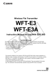
LQ
Document E8141_Issue1
FIELD COUPLING TESTER USER INSTRUCTIONS
Notes and issue History
Issue
1
Action
Special Notes / Cautions
Initial Release
Note that the E3A User Manual can be used as a reference document, but E8141 summarises
the modification and operation as a Field Coupling Tester
Document Description
Document number
FIELD COUPLING TESTER USER INSTRUCTIONS
E8141
Issue
Change
Drawn
Date
1
Initial
Release
Keith Britton
16th May
2007
Filename – E8141_Field Coupling Tester
User Instructions_Issue 1.doc
Copyright © 2007 QRG Ltd.
Checked
Approved
Page 1 of 6
LQ
Document E8141_Issue1
1. The main components of the Field Coupling Tester are;
Field Coupling Tester components;
9V
BATTERY
MODIFIED E3A
EVALUATION
BOARD
REMOTE
SENSOR
ASSEMBLY
Filename – E8141_Field Coupling Tester
User Instructions_Issue 1.doc
Copyright © 2007 QRG Ltd.
Page 2 of 6
LQ
Document E8141_Issue1
2. The E3A board is modified by cutting through the centre of the PCB Sensor Pad and connecting
one half to PCB Ground.
E3A Modification;
3. The Remote Sensor Assembly is a simple PCB (7537) with a ‘split’ electrode (similar to the
modified PCB sensor pad), shielded cable and connector to plug into P2 on the modified E3A
board.
Remote Sensor Connection Detail;
NOTE – When the Remote Sensor is used, the non-copper side is the sensing surface;
Filename – E8141_Field Coupling Tester
User Instructions_Issue 1.doc
Copyright © 2007 QRG Ltd.
Page 3 of 6
LQ
Document E8141_Issue1
4. When the Remote Sensor Assembly is connected, slide SENSOR SELECT towards P2
When the PCB Sensor is used, slide SENSOR SELECT away from P2
5. Calibration of Field Coupling Tester;
a. Ensure that;
QT300 IC is installed at U1,
‘DEVICE’ is set to QT300,
‘MODE’ is set to ‘ACTIVE’
b. Connect 9V Battery to B1 and switch on (S1).
c. Keep everything clear of PCB Sensor area; Press and release ‘LOWER’ calibration
button.
Filename – E8141_Field Coupling Tester
User Instructions_Issue 1.doc
Copyright © 2007 QRG Ltd.
Page 4 of 6
LQ
Document E8141_Issue1
d. Place metal object (eg Coin) centrally on the Sensor area; Press and release ‘UPPER’
calibration button.
e. Calibration when using the Remote Sensor Assembly is the same procedure as above
(Ensure SENSOR SELECT is in the correct position)
6. Once calibrated, the ability for any object/material to couple field to ground can be assessed
and compared. Place the object centrally on the sensing area and observe the Delta Signal
Bargraph, Counts or % on the LCD display.
Typically, the lower the Delta Signal, the better the object of material is when used as a sensor
surface for QRG Ltd’s products.
When using the Remote Sensor Assembly, ensure that the sensing area is in fully contact with
the material being evaluated, and ensure that a reference reading is also taken without the
material present, e.g.
Measure
Material Delta
signal
Compare with
Delta signal
obtained here
Filename – E8141_Field Coupling Tester
User Instructions_Issue 1.doc
Copyright © 2007 QRG Ltd.
Page 5 of 6
LQ
Document E8141_Issue1
Examples:
Acrylic cover; Low Delta Signal – ‘Excellent’ material for Quantum Research Group’s products.
Button with buried conductive layer; Medium Delta Signal – ‘Good’ material
Paper on sensor
Effect of conductive material;
Paper with graphite pencil mark
*** END OF DOCUMENT ***
Filename – E8141_Field Coupling Tester
User Instructions_Issue 1.doc
Copyright © 2007 QRG Ltd.
Page 6 of 6