1
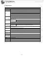
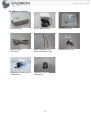
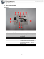
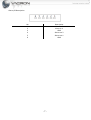
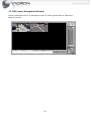
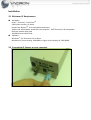
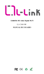
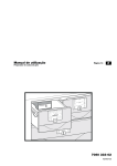
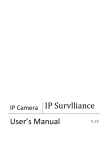
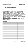
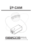
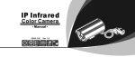
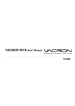
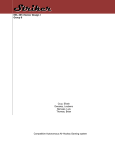
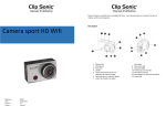
IP Camera
User’s Manual
V_1.2
Contents Table
Over View ........................................................................................................................................................ 3
1.1 Feature.......................................................................................................................... 3
1.2 Specifications ................................................................................................................. 4
1.3 What’s in the box ........................................................................................................... 5
1.4 What’s in the Hardware .................................................................................................. 6
1.5 CMS Camera Management Software ................................................................................ 8
Installation....................................................................................................................................................... 9
2.1 Minimum PC Requirement .............................................................................................. 9
2.2 Connecting IP Camera to your computer........................................................................... 9
2.3 Live View ..................................................................................................................... 14
2.4 Status......................................................................................................................................... 17
2.4.1 Information ......................................................................................................................... 17
2.4.2 PING .................................................................................................................................... 17
2.5 Settings ...................................................................................................................................... 18
2.5.1 Video ................................................................................................................................... 18
2.5.2 Camera ................................................................................................................................ 21
2.5.3 Audio ................................................................................................................................... 23
2.5.4 Date Time ............................................................................................................................ 24
2.5.5 Network............................................................................................................................... 24
2.5.6 Alarm ................................................................................................................................... 25
2.6 Maintenance ............................................................................................................................. 27
2.6.1 User Account ....................................................................................................................... 27
2.6.2 Profile .................................................................................................................................. 28
2.6.3 Firmware Update ................................................................................................................ 28
2.6.4 Restart ................................................................................................................................. 29
2.6.5 Language ............................................................................................................................. 29
Appendix A – IPSearcher for searching IP Camera on LAN .................................................................. 30
-2-
Over View
1.1 Features
5-megapixel CMOS Sensor
Real-time H.264, MPEG-4 and MJPEG Compression (Triple Codec)
Simultaneous Multiple Streams
Built-in SD/SDHC Card Slot for On-board Storage
Built-in high sensitive microphone for Box/Bullet series
Supports ONVIF Standard to Simplify Integration and Enhance Interoperability
Supports H/W Watchdog
-3-
1.2 Specifications
Specifications
System
Image Sensor
LENS
Video
Image Settings
Audio
Networking
Alarm And
Event
Management
Users
On-board
Storage
Maintenance
I/O
Power
Weight
Dimensions
Operating
Environments
CPU:TI DM365 SoC
Flash:32MB
RAM:128MB
HIGH QUALITY 5-MEGAPIXEL 1/2.5”CMOS
SUPPORT AUTO IRIS C/CS MOUNT LENS
H.264: 30 fps at 1280x720 , Highest Resolution: 8 fps at 2592x1920
MPEG4: 30 fps at 1280x720 , Highest Resolution: 8 fps at 2592x1920
MJPEG: 30 fps at 1280x720 , Highest Resolution: 8 fps at 2592x1920
Compression: H.264, MPEG-4 & MJPEG Streaming:
Triple Codec (H.264 MPEG-4 JPEG) Selectable
Support Simultaneous multiple streams
Adjustable image size, quality, and bit rate
Time/Date stamp and text caption overlay.
Configurable brightness, contrast, saturation, sharpness, white balance and exposure AGC
AWB AES BLC
MPEG-4 AAC audio encoding
Format
G.711 audio encoding
Built-in high sensitive microphone with 5M maximum audible area. Supports audio mute
Support External Speaker for Alarm siren
INTERFACE
10/100 Mbps Ethernet, RJ-45
SUPPORTED
IPv4, TCP/IP, DHCP, HTTP, FTP, SMTP, RTSP, SNTP, DNS
PROTOCOL
、
、
、
、 、
Motion Detection
2 D/I & 2 D/O for external sensor and alarm
Alarm siren output (require external speaker)
Event notification using SMTP, or FTP
8 clients on-line monitoring at the same time
Multi-level user access control with password protection
SD/SDHC card slot : Stores snapshots and video clips
Supports online firmware upgrade
RJ-45 Ethernet x 1, Power connection x 1, SD-card slot x 1, Auto Iris Plug x 1,
RS-485 x 1, Alarm I/O x 1 , Reset Button x 1
DC12V PoE (OPTIONAL)
Net weight: 345 g
Long: 152mm Width: 70mm Height: 50mm
Temperature: 0 ~ 45 °C
Humidity: 90%
、
、
、
-4-
1.3 What’s in the box
IP Camera x1 pc
DC 12V Adaptor x1 pc
Software CD x1 pc
Ethernet Cable
(CAT.5)x1 pc
RS-485 Cable(left) x1 pc
Alarm Cable(right) x1 pc
Installation Kit x1 set
Megapixel Auto IRIS Lens x1
pc(Optional)
SD Memory Card x1
pc(Optional)
-5-
1.4 What’s in the Hardware
Panel Details
1
2
3
4
5
6
10
7
8
No.
1
2
3
RS-485
Buzzer
SD-Card
Description
4
Alarm I/O
5
Mini- USB
6
Auto IRIS
7
Video Out
8
Default
9
DC12V
10
LAN
9
Function
For PTZ Camera connection
This provides Audio signal to the external speaker
For saving image files
Alarm signals I/O
USB device cable can be used to connect to the PC
Auto IRIS connector
It provides composite video signals to NTSC/PAL
monitor
To restore factory default values
button for 6 seconds
Power connector
Ethernet 10/100M connector
-6-
-- Press this
Alarm I/O Description
No
1
2
3
4
5
6
Description
Alarm in 2
Alarm In 1
GND
Alarm out 2
Alarm out 1
GND
-7-
1.5 CMS Camera Management Software
You can install CMS on a PC to management your IP Camera, please refer to “CMS User's
Manual-V1.0.pdf”.
-8-
Installation
2.1 Minimum PC Requirement
Hardware:
R Pentium○
R DUAL CoreTM
Intel○
2 GB system memory or above
R 9.0c compatible sound card
Sound Card: DirectX○
R 9.0c compatible
Video Card: 3D hardware accelerator card required – 100% DirectX○
Ethernet network port/card
10/100 Ethernet switch/hub
Software:
R XP Service Pack 2 or above
Windows○
Resolution of screen setting: 1280x960 or higher for the display of 720P/1080P
2.2 Connecting IP Camera to your computer
Change computer’s IP address – Please set IP address to be “192.168.1.3”.
(You can also searching IP Camera in LAN with the tool – IPSearcher, please refer to
appendix A)
Click [Start-> Control Panel]
Click [View network status and tasks]
Click [Change adapter settings]
- 10 -
Double Click [Local Area Connection]
Click [Properties]
- 11 -
Double click [Internet Protocol Version4(TCP/IPv4)]
Select [Use the following IP address] and enter IP Address, Subnet mask and Default gateway
then press [OK].
- 12 -
Login IP Camera with a WEB browser
You may visit IPCamera’s homepage by IE or other compatible web browsers.
Running a browser and enter IP Camera’s IP- 192.168.1.201 in URI.
Default account: admin
Default password: 9999
It displays system information after you login IP Camera.
- 13 -
2.3 Live View
R , Chrome○
R or Firefox○
R , you have to install QuickTime○
R Player or the
If you prefer using Safari○
browsers can’t display video. If you use Windows Internet Explore it will ask you install ActiveX
program when you first login.
- 14 -
You may need to change security parameter for Live View Player playing video well.
Enter [Control Panel] then click [View network status and tasks].
Click [Internet Options].
- 15 -
Enter [Security] page then click [Custom level].
Set [Download unsigned ActiveX controls] to be [Prompt].
- 16 -
2.4 Status
2.4.1 Information
It displays hardware and firmware version of IP Camera.
2.4.2 PING
Use “Ping” to verify if a remote peer is reachable. Enter a remote IP address and click “Test” to
ping the remote host. The result would be shown on Result Table.
- 17 -
2.5 Settings
2.5.1 Video
In this page you can set parameters for Video Stream.
Camera: Type the camera title.
Stream Type: Select the stream type.
Single : This will have single stream use cases only.
Dual : This will enable dual stream use case with second resolution.
Triple: This will enable triple stream use cases.
◎
◎
◎
Codec: Select the required codec. The options available are:
Stream Type
Single Stream
Dual Stream
Triple Stream
Codec Combo
[H264]、 [MPEG4]、[MegaPixel]
[H264+JPEG]、[MPEG4+JPEG]、[Dual H.264]、
[Dual MPEG4]、[264+MPEG4]
[Dual H264+JPEG]、[Dual MPEG4+JPEG]
- 18 -
Resolution: Select the required image resolution for the streams. The options available are:
1) Single Stream mode:
Codec
H.264
MPEG4
MegaPixel
Selectable resolution
[H264:720]、 [H264:D1]、 [H264:SXVGA]、 [H264:1080 ]、
[H264:720MAX60]
*Example- [H264:720]:
: Video codec is H.264 with vertical
resolution @ 720p.
[MPEG4:720]、 [MPEG4:D1]、 [MPEG4:SXVGA]、
[MPEG4:1080 ]、 [MPEG4:720MAX60]
[H264:2MP]、 [JPG:2MP]、[H264:3MP]、 [JPG:3MP]、
[H264:5MP]、[JPG:5MP]
*Example-[H264:2MP]:
:Video codec is H.264 with 2 MegaPixel.
2)Dual Streams mode:
Selectable resolution
Codec
H.264+JPEG
[H264:720 +JPEG:VGA]
[H264:D1+JPEG:D1]
[H264:720+JPEG:720]
*Example-[H264:720 +JPEG:VGA]:
:The first video stream codec
is H.264 with resolution @720p. The second video stream
codec is JPEG with resolution for VGA(640*480)
MPEG4+JPEG
[MPEG4:720 +JPEG:VGA]、[MPEG4:D1+JPEG:D1]
[MPEG4:720+JPEG:720]
Dual H.264
[H264:720+H264:QVGA]、[H264:D1+H264:D1]
[H264:D1+H264:QVGA]、[H264:1080+H264:QVGA]
Dual MPEG4
H.264+MPEG4
、[MPEG4:D1+MPEG4:D1]
[MPEG4:D1+MPEG4:QVGA]、[MPEG4:1080+MPEG4:QVGA]
[MPEG4:720+MPEG4:QVGA]
[H264:D1+MPEG4:D1]
3)Triple Streams mode:
Codec
Dual H264+JPEG
Dual MPEG4+JPEG
Selectable resolution
[H264:720+JPEG:VGA+H264:QVGA]
[MPEG4:720+JPEG:VGA+MPEG4:QVGA]
- 19 -
TAB for Stream 1- Stream 3: For setting individual parameters for each stream.
Frame Rate: Select the required frame rate for JPEG, MPEG4 and H.264. This changes based on the
selected codec combo.
Bit Rate: Type the required bit-rate for both MPEG4 Setting and H.264 Setting. Bit-rate values
ranges between 64 and 10000 from stream1 and 64 to 8000 for stream2/stream3.
Rate Control: Select the required option
OFF: This will switched off the rate control and will encode the frame in constant QP
mode for all MBs (Macro-Blocks).
MPEG4 will be coded with QP = 4
H264 will be coded with QP = 28
VBR : Variable Bit rate (max_delay set is for 1000msec).
CBR : Constant Bit rate. This will have frame skips to maintain bit rate with specified VBV
buffer (max_delay set is for 1000msec).
◎
◎
◎
Quality Factor (For JPEG): Type the selected image quality required for JPEG stream. Quality value
can vary from 3 to 99.
Overlay Setting:
Select Enable Date and Time check box to activate the function.
Date: This will enable/disable insertion of Data as per the position specified corner of the
captured image.
Time: This will enable/disable insertion of Time as per the position specified corner of the
captured image
Text: This will enable/disable insertion of Text as per the position specified corner of the
captured image
◎
◎
◎
Local Display Video: Select one of the following options of the display device:
OFF: Will switch off the display
NTSC : Will switch to NTSC display @ 30fps
PAL : Will switch to PAL display @ 25fps
◎
◎
◎
Note:
For resolution not having D1 or VGA in the codec combination as a resolution, primary resolution will be sent for
display. If primary resolution above D1 like 720P, center portion with D1 width and height is sent for display.
For 1080P, QVGA resolution is used for display.
For SXVGA and MegaPixel mode, 256x192 is used for display
For 720MAX60 and 5MP mode, display is not enabled.
OSD may be cropped based on the Display TV properties and where center portion is sent display, OSD like
Date/Time etc will not be displayed on TV screen.
Mirror: Select the required option
OFF
VERTICAL: Flips the data in vertical direction
HORIZONTAL: Flips the data in horizontal direction
BOTH: Flips the data in both directions, equivalent to 180 rotation
◎
◎
◎
◎
- 20 -
2.5.2 Camera
Brightness: Select the required brightness level that ranges from 1 to 255. A brighter scene
appears, if you choose higher level of brightness.
Contrast: Select the required range. The range available is between 1 to 255.
Saturation: Select the required saturation level that ranges from 1 to 255. A vivid scene appears, if
you choose a higher level of saturation.
Sharpness: Select the required range of sharpness. The range available is between 1 to 255.
Back Light Compensation(BLC): Select one of the following options to turn on/off the backlight
function:
Backlight: Select the required range. The range are set to Min, Mid and Max values based on user
selection.
Flicker Control: Select one of the following options of the Flicker device:
◎ NTSC/60Hz : This will compensate for 60Hz flicker and will put the display if selected to
NTSC mode
◎ PAL/50Hz : This will compensate for 50Hz flicker and will put the display if selected to PAL
mode
White Balance Mode: Select one of the following options:
Day and Night: Select one of the day or night mode.
- 21 -
Video Stabilization: Select one of the following options
◎ OFF/ON button to enable/disable this option.
Note:
Video Stabilization and Lens Distortion Correction are not supported for resolution above 720P.
Lens Distortion Correction: Select one of the following options
◎ OFF/ON button to enable/disable this option.
Image Sensor mode: Select the required option. The options available for tuning these are:
◎ Binning: 2560H x 1440V FOV binned (2x2) in sensor to 1280H x 720V for 720P resolution as
primary stream. This enables enhance low-light performance.
◎ Skipping: 2560H x 1440V FOV skipped (2x2) in sensor to 1280H x 720V for 720P resolution
as primary stream. This helps in increasing capture rate.
◎ Window: This will capture the input video at 1080P resolution and resize the desired
resolution. This will have binning switched OFF. For ex: for 720P resolution as primary
stream. Sensor will send data at 1080P resolution and then resize to 720P resolution. This is
enabled to keep constant FOV for all modes/resolutions.
Note:
Binning reduces resolution by combining adjacent same color image pixels to produce one output pixel.
All the pixels in the field of view, contribute to output image in bin model. As a result, low-light
performance also gets enhanced.
Skipping mode is used to increase frame rate and to reduce image size without reducing the field of view.
Skipping reduces
2A Mode: Select the required option. The options available are:
◎ OFF: 2A is switched OFF
◎ AE: Only Auto Exposure is switched ON
◎ AWB: Only Auto White Balance is switched ON
◎ AEWB: Both Auto Exposure and Auto White Balance are enabled
Noise Filter: Select the advance features.
◎ OFF/ON button to enable/disable this option.
◎ SNF: Spatial Noise Filter will be ON
◎ TNF: Temporal Noise Filter will be ON
PTZ: (Optional)
◎ Protocol: Select a protocol for IPCamera and Pan-Tilt System.
◎ Device ID/ Baud Rate: Select device ID(or address) and baud rate assigned on Pan-Tilt
System.
◎ Speed: The Pan-Tilt System is moving quicker if you set it to be higher..
◎ Min. Move Time: Some control device sends PTZ move and stop command at the same
time. Enable this option for IPCamera to transit PTZ moving command in a fixed period of
time.
- 22 -
2.5.3 Audio
Enable Audio: This will switch ON/OFF the audio in camera.
Audio Mode: You can change the audio mode in the Network camera in one of the following ways:
◎ Only Mic: Enables only audio capture in camera.
◎ Only Speaker: Enables only audio playback in camera.
◎ Both Mic & Speaker: Enables both audio playback & capture in camera.
Input Gain: Sets the input capture gain, values set from 1-100, setting this value to minimum will
not mute the camera as this will set only the gain to lower values.
Encoding: Set which codec is used for encoding. G711 and AAC LC is supported currently.
Sample Rate: Supports 8Khz and 16Khz sampling options from this drop down menu.
Alarm Level: Select the range for triggering the Audio alarm. For ex: if 50% is selected and in Alarm
Page, Audio Alarm is selected, then, if any audio samples captures are more than
50*32768/100=16384 value, alarm will be triggered. This has no significance if Audio Alarm is not
selected in Alarm Page.
Output Volume: Set the audio playback volume, values set from 1-100.
- 23 -
2.5.4 Date Time
The NTP configuration allows IP Camera obtain time from an NTP server or sync with your
computer.
PC Time: It displays current time on your computer.
Device Time: It displays current time on IP Camera.
Manual: Click [PC Time] then [Accept] button to sync IP Camera’s time with your computer.
Synchronize with Time Server:
◎ SNTP Server: Enter IP or FQDN of an SNTP server.
◎ Time Zone: Select the required time zone from the drop-down list. If this is not done, the
time given by the unit may be incorrect.
2.5.5 Network
There are two types of IP network settings, if there is a DHCP server or broad band router setup in
your IP network, you may set it to be DHCP. If you set up a NVR(Network Video Recorder) to
recording IP Camera’s video, it is better set IP type to be “Static IP”.
- 24 -
2.5.6 Alarm
Enable Alarm: This will switch ON/OFF the alarm in camera
Alarm Duration: From the drop-down list, select the length of the alarm (10sec, 30sec, 1 min, 5min, 10min, Non-Stop).
This option will determine how long the ALARM signal should be ON after it gets Detected.
Alarm Trigger: You can change the Alarm Trigger mode in the Network camera:
Ethernet Lost: Activates or deactivates the alarm when the network connection is down or network cable is
tampered with
Audio Alarm: Activates or deactivates the alarm at high audio level based on the value set in Alarm Level in
Audio Page.
For External Triggers Input : Select one of the following options
◎ ON: Corresponds to the ALM-IN in the IP SURVEILLANCE CAMERA , you can use GPIO connector.
◎ OFF: Corresponds to the ALM-IN in the IP SURVEILLANCE CAMERA , GPIO connector is shut down.
For External Triggers Output : Select one of the following options
◎ ON: Corresponds to the ALM-OUT in the IP SURVEILLANCE CAMERA , you can use GPIO connector.
◎ OFF: Corresponds to the ALM-OUT in the IP SURVEILLANCE CAMERA , GPIO connector is
deactivated.
- 25 -
Block of Motion Detection
There are 12 independent areas for motion detection. Select which block for IPCamera detecting.
Sensitivity: There are three levels, please set sensitivity to be low if this camera monitoring outdoor.
Customized Threshold: You can also set sensitivity by input a value, the higher value you set the more sensitivity
for camera.
- 26 -
2.6 Maintenance
2.6.1 User Account
There are three operating levels when entering the Web UI. Logging-in as the admin allows you to
change all settings.
Admin: You can operate all functions in Web interface.
Operator: You can operate all functions in Web interface except User Account.
Viewer: You can only monitor the Web interface, but cannot operate all function and set
parameters.
HTTP Port: You can change listen port of WEB GUI.
- 27 -
2.6.2 Profile
Backup Configurations: Click the Backup Settings button to save your current settings to a file.
Restore Configurations: You can backup settings to a file and restore settings from that file. You
also can restore all settings back to default by selecting Restore Default Configurations and click
Restore.
2.6.3 Firmware Update
Please select then click [Update] button to upload firmware. During the upgrade process please don’t
click on any other button or don’t try changing camera setting, this may lead camera to abort upgrade process
and subsequent reboot will result in undesired behavior.
- 28 -
2.6.4 Restart
Tick [Restart] then click [Accept] button to restart IPCamera.
2.6.5 Language
Select a language for WEB GUI.
- 29 -
Appendix A – IPSearcher for searching IP Camera on LAN
There is a tool which can running on a computer to search IP Camera in local area network. It
allows you to change IP Camera’s IP address much easier.
Enter the folder [Tools] in the CD.
Double click [IPSearcher].
- 30 -
R
Running [IPCameraSearcher] (It may show “IPCameraSearcher.exe” if your Windows○
displays full file name.)
Click [Search(s)]
- 31 -
It displays searched device(s) in 5-10 seconds, please select an IP Camera
then click [UpdataIP(I)].
Enter User Name and Password then enter new IP, Netmask and Gateway.
(The default User Name is “admin”, Password is “9999”)
Press OK then open a browser for connecting to this IP Camera.
- 32 -