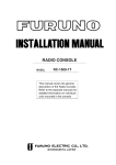
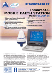
1
TECDIS Installation Manual
Chapter 6: Checklist regarding installation
6.1 Checklists prior to completion of TECDIS installation.
Item: Task to be performed:
OK: Comments
1
Verify that all selected ports are receiving/transmitting
data, and that ports have been given names on both
main and back-up TECDIS. Names shall be according
to the data they are receiving/transmitting.
2
Verify that sensor data is correctly distributed between
main and back-up TECDIS (NMEA server program).
3
Verify that one single action do not result in loss of
position on both main and back-up TECDIS.
4
Verify that main and back-up TECDIS and respective
equipment are connected to a proper UPS.
5
Verify that boat size are correct compared to chart on
both main and back-up TECDIS.
6
Perform monitor color calibration on main and back-up
TECDIS.
7
Verify that alarm function on both main and back-up
TECDIS is working properly.
8
Check that TECDIS transmits alarm to external
systems.
9
If installed, verify generation of conning picture and
correct display of sensor data on conning monitor
(check against engine telegraph, speed repeaters, gyro
repeaters etc)
10
Verify audible signal from alarm speaker on TECDIS
11
Verify sensor data (correct size of vessel etc) is filled in
on main and back-up TECDIS.
12
Verify that back-up of default setup values have been
performed (save setup default values) on main and
back-up TECDIS.
13
Verify that installed charts have been correctly installed
on both main and backup TECDIS (if installed), and
that charts license matches.
14
Unplug TECDIS USB-key, restart TECDIS to verify it
starts up in normal mode (chart program starts
automatically) and boat symbol and sensor data are
displayed.
15
Fill in hardware/software fact sheet and file it in ships
documents and in technician personal files.
Page 0
TECDIS Installation Manual
Item:
1
Hardware
Keyboard Main
2
Keyboard Back-up
3
Processor Main
4
Processor Back-up
5
Telchart alarm interface
6
Trackball Main
7
Trackball Back-up
8
Analog signal collector
9
Monitor Main
10
Monitor Back-up
11
Conning monitor
12
Alarm loudspeaker
13
MOXA interface
14
Additional units
15
Additional units
16
Additional units
Item:
1
Software
TECDIS Main
2
TECDIS Back-up
3
C-Map SDK Main
4
C-MAP SDK Back-up
5
Additional software
6
Additional software
7
Additional software
Item:
1
2
License
TECDIS license # Main
Page 1
Model/type:
Serial no.
Version:
Description:
Number:
Description:
TECDIS license # Back-up
NB: License for charts is not possible to list, as there is one license per chart.
TECDIS Installation Manual
Page 2
6.2 Checklists prior to completion of TECDIS TC and TECDIS AW
installation.
If installation includes Track Control functionality, the following tests must be performed.
TECDIS 1 and 2
No.
Function
Requirement
Results
Harbour Acceptance Test (15 minutes)
TECDIS 1:
1
External data
Go to setup menu and verify NMEA inputs are valid. Check
input values for position and course.
□Good □NG □N/A
TECDIS 2:
□Good □NG □N/A
2
Verify that TECDIS receives valid sensor data from a minimum
of:
• Two independent positioning sensors
External data
• Two independent heading sensors
• A speed sensor
TECDIS 1:
□Good □NG □N/A
TECDIS 2:
□Good □NG □N/A
TECDIS 1:
3
Alarm system Verify that TECDIS is connected to a separate alarm system.
□Good □NG □N/A
TECDIS 2:
□Good □NG □N/A
TECDIS 1:
4
System status Check that no alarms/warnings are pending in alarm window.
□Good □NG □N/A
TECDIS 2:
□Good □NG □N/A
5
1,Select setup menu, chart utilities, chart licenses
2,Verify that licences are valid for intended voyage
Chart database 3,Click C-Map chart update
4,Verify that charts are updated in update log
TECDIS 1:
□Good □NG □N/A
TECDIS 2:
□Good □NG □N/A
Sea Trial Test (15 minutes)
6
1,Activate ARPA on radar and select a target.
AIS and ARPA
2,Click the symbol button of [ARPA Targets].
Targets
3,Click the symbol button of [AIS Targets].
(If present)
AIS and ARPA Targets are displayed on the top of charts.
TECDIS 1:
□Good □NG □N/A
TECDIS 2:
□Good □NG □N/A
TECDIS 1:
7
Correct indication is shown at the each configured window on
Conning display
the Conning Display. Verify that selected sensors used by
(If present)
heading, position is correctly indicated.
□Good □NG □N/A
TECDIS 2:
□Good □NG □N/A
TECDIS Installation Manual
Before start TEST, routes must be created or transferred from
other TECDIS:
1,Press the [Plan] key, icon with number 1 indicated is active.
This means primary route will be selected. Choose a route
with boathook icon.
2,Press [YES] icon to activate route.
Route Monitoring 3,Route is then shown on displayed charts.
8
4,To display secondary route choose icon with button 2
indicated. Repeat procedure as for primary route.
5 To exchange primary and secondary route, press icon with
1↔2 indicated.
6. Observe that correct warings is activated as appropriate.
7. Click alarm icon for display of alarms and warnings on route.
8. Test that activating tracksteering is successful.
Page 3
TECDIS 1:
□Good □NG □N/A
TECDIS 2:
□Good □NG □N/A
TECDIS 1:
9
Radar overlay Check that radar overlay from radar is displayed on display after
(If present) pressing radar overlay icon.
□Good □NG □N/A
TECDIS 2:
□Good □NG □N/A
10
Aids to
navigation
Verify that TECDIS handle different functions like;
1. Disconnect position sensors and observe dead reckoning
performance, verify that alarm is given: pos sensor ½ lost.
2. Activate track dialog and set past tracks visible by clicking
on “show” icon.
3. Enter manual fix, by activating “bearing” icon. Click on
center button on mouse when mouse is in position of visual
object. Use observed gyro bearing to make a red line in
chart towards estimated position. Repeat procedure to make
two lines resulting in a cross bearing.
4. Update charts, enter chart utilities menu, choose C-Map
charts update. Use semi-auto update. Create a update
request file on memory stick.
Send file to [email protected] and load received file into
TECDIS. Update loaded successfully shall be presented
when update Is completed.
5. Activate a route in route menu. To alter at route underway,
click on “Edit” icon in route menu. Modify route and click on
“OK” icon. Route is now altered. When at track steering
mode, 3 waypoints are not allowed to alter, last waypoint,
next waypoint and waypoint after next.
6. Manual adjustment for position is available in setup menu,
click on “nav. position offset” icon and a dialog box appear in
top right corner of map. Enter offset values as appropriate.
TECDIS 1:
□Good □NG □N/A
TECDIS 2:
□Good □NG □N/A
TECDIS Installation Manual
Page 4
Anschütz NP 2025 PLUS Adaptive Autopilot
No.
1
2
3
4
5
6
Function
Requirement
Harbour Acceptance Test (15 minutes)
Correct number is shown at each box of below.
External data
“Heading”, “Speed”
1,[HEADING CONTROL] is activated when steering mode
switch is set to “auto”. Present heading is displayed in heading
display and in preset heading display. Present heading is
activated as set heading.
2. Verify parameter settings for rudder, yawing, counter
rudder, rudder limit, ROT limit and radius value. Verify mode
Heading Control of heading change, radius or R.O.T. mode by observing key
lamp.
3. Alter set course by either turn knob and push set button to
acknowledge or push and turn knob. Observe correct rudder
response.
4. Observe rudder movement.
5. Observe that max rudder limit is not exceeded.
1,Rudder moves to 10 degrees PORT when SET HEADING is
Steering Control set by 20 degrees below Gyro heading.
2,Confirm the actual rudder angle by rudder angle indicator.
1. Change operating mode from hand to heading control at
Track Control TECDIS , verify that correct mode is indicated
on TECDIS and conning monitor also.
Function
2. Shift from heading control to manual mode by switching
steering mode selector. Verify that change to manual mode is
possible from all modes with a single operator action.
1. Change set course 50 deg to starboard, off-heading alarm not
to be activated during setting of new course. Alarm is deFunction
activated for a time period that is a function of present course
and new desired course.
Function
Test override tiller in modes: hand, heading control and track
control. Autopilot to go to hand
Results
□Good □NG □N/A
□Good □NG □N/A
□Good □NG □N/A
□Good □NG □N/A
□Good □NG □N/A
□Good □NG □N/A
Sea trial test (240 minutes)
Response and stability of "Heading Control” steering.
1,Observed overshooting should max 2 deg on 10 deg course
change and max 5 deg on 60 deg course change.
2,Repeat another side course change with same value.
1
2
2
Heading Control
EMC
Starboard 10 deg turn with NAV FULL speed (If available).
Port 10 deg turn with NAV FULL speed (If available).
Starboard 60 deg turn with NAV FULL speed.
Port 60 deg turn with NAV FULL speed.
Tests to be repeated with half speed ahead.
Testing of interference of radio transmissions while in heading
control, observe system while:
1. Transmitting a call with FS-2570
2. Transmitting a call with VHF’s
3. Transmitting a message with Felcom-15 1&2
4. Transmitting a call with Felcom-70
Track Control Steering function test should be performed as follow in the next
Steering
lists "Track Control Test " and “Fail to Safe Properties”
□Good □NG □N/A
□Good □NG □N/A
□Good □NG □N/A
TECDIS Installation Manual
Page 5
Track Control System Test
Items to be checked during sea trial
No.
1
Item
2
Route
3
Route
monitoring
Content
The following units have to be tested prior
to the Track Control test:
ECDIS
AUTOPILOT
STEERING GEAR
Create a test route for Track Control in keeping
with the vessel maneuverability as per shown
example attached (or import by file).
1. Enter route menu, check that icon “1” is
activated (primary route). Use boathook to
select route from previous test item. Click yes
when asked to activate route.
2. Check that route monitoring parameters are
shown in right menu (XTE, next waypoint info
etc. )
4
Track
keeping
1. Check that ship follows the test route
selected on ECDIS. *Recommend test speed is
normal sea speed
2. Check performance according item 1 with speed
reduction applied in one turn.
3. Check performance according item 1 with
inducing current effect by using bow thruster
during turn.
5
Alarms
1. Set WP pre-warning and WP approach time on
the ECDIS as per drawing below. Verify that WP
approach Alarm is generated when the ship
approaches the WP.
2. Verify that separate Alarm system activates
back-up navigator alarm when WP pre-warning
and WP alarm on ECDIS is not acknowledged.
3. Set alarm for gyro mis-match to minimum in
TECDIS Setup program. Wait for alarm to be
raised.
4. Activate route and use “Heading Control” mode
on autopilot. Steer outside channel limit to
generate XTE alarm.
5. Set “Heading off” alarm low and use bow
thruster to provoke a heading drift. Verify that
alarm is raised.
Result
Remarks
TECDIS Installation Manual
Page 6
Example of route for Track Control testing
WPT 3: 135 deg turn port, WPT 5: 135 deg turn starboard (both with minimum radius*)
WPT 4: 60 deg turn port, WPT 7: 60 deg turn starboard (both with 2 NM radius)
* Minimum radius to be settled after calculations from yard.
TECDIS Installation Manual
Page 7
ECDIS Scheduled Track
Course 90 deg
AP Scheduled
Course 90 deg
Wheel Over Point
WP Approach alarm
sec before wop
30
Pre-Warning alarm
120sec before wop
Trial Speed
NSR
Approach run
Ship start turn from
wheel over point with 90
deg Angle
TCS Test 2)
Failure point
at straight leg
Turn radius is
with 1.0NM
TCS Test3)
Failure point in turn.
TECDIS Installation Manual
Page 8
Fail to Safe Properties
Item
1
2
3
Fail
Position sensor antennas
to be blinded off.
Disconnect position
sensor on a straight leg.
Disconnect position
sensor during max radius
turn.
Track Control (TCS)
When either of position sensor
acquisition stops, TCS emits alarm but
continues to function utilizing acquired
position from other position sensor,
LOG, and GYRO. When both position
sensor acquisition stops, TCS emits
alarm but begins navigation utilizing
estimated position made available by
LOG and GYRO. Then it (after 10min)
automatically switches to Radius mode
and manual maneuver will be in effect.
Same as above
Alarm will be emitted only from ECDIS
which places no influence on TCS
function.
Turn Heading Control
System rudder limit to
min value during min
radius turn.
Disconnect serial
link to heading
controller during
straight leg.
Not available.
6
Disconnect serial
link to heading
controller during
turn.
Emits alarm and stops TCS function
simultaneously. Automatically switches
to Radius mode and manual maneuver
will be in effect after turning to the predetermined maximum degree.
7
Disconnect speed log
during straight leg/
or turn.
Simulate failure in
ECDIS.
Simulate failure in
conning display.
Disconnect rudder
feedback.
Although emits alarm, two position
sensor data inputted maintains the
normal function.
Same as item 5 or 6.
4
5
8
9
10
Emits alarm and stops TCS function
simultaneously. It automatically
switches to Radius mode and manual
maneuver will be in effect.
Not influential
Emits alarm by Alarm System. If the
deviation between order rudder angle
and actual rudder angle is 5deg or more,
the Alarm System emits alarm and
freezes the actual rudder angle at this
time.
11
Simulate failure in
Autopilot
Emits alarm by Alarm System and stops
TCS function. Rudder angle is frozen at
this time.
12
Simulate failure in
No.1 gyro.
Not influential
13
Check that second gyro
is automatic applied in
case of failure in the
active gyro.
Not influential
Test
Remove No.1
position sensor
antenna
Remove No.2
position sensor
antenna
Remove No.1/2
position sensor
Remove No.1
position sensor
output connector
during maximum
radius turn.
Adjustment of
rudder limit is not
available.
Remove Track
Control connection
from ECDIS while
sailing straight
ahead.
Remove signal
cable exclusively in
use for Auto Pilot
outputted from
ECDIS while
turning.
Remove LOG input
outputted to ECDIS
while turning.
Turn off ECDIS
Turn off Conning
Display
Remove rudder
feedback input
outputted to Alarm
System while
turning.
* This test is
dangerous !
Remove power
connection to
autopilot while
turning.
* This test is
dangerous !
Switches
automatically
from No.1 to No.2
Result
TECDIS Installation Manual
Page 9
6.3 Additional checklist prior to completion of TECDIS AW installation
No.
Item
1 Conning
Content
Verify that when one of the ECDIS processors
lose sensor data on one serial line, display of
sensor data (relevant according to failed serial
line) on conning monitor is not affected.
2
General
Verify that installation is done according to block
diagram for TECDIS AW system.
3
General
Verify that installation is done according to
functional description given for TECDIS AW
system.
4
General
Verify that required conning info according to
NAUT AW requirements are displayed correctly.
5
Gyro
Verify that requirements set forth in section 1.7
are fulfilled.
Result
6.4 Installation Notes
6.5 Track-record of performed installation
Name of vessel:
Date of installation:
Name of technician:
Checklist performed:
During all installations this checklist shall be filled in, this is for verifying a proper
installation of the ECDIS system onboard.
Remarks