1
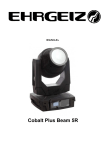
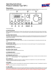
KMT - Kraus Messtechnik GmbH Gewerbering 9, D-83624 Otterfing, Germany, 08024-48737, Fax. 08024-5532 Home Page: http://www.kmt-telemetry.com, Email: [email protected] TEMPTEL 4/8 4/8 channel Telemetry System for Thermocouples K or J Inductive digital transmission from rotating shafts User Manual INSTRUCTIONS FOR QUALIFIED PERSONNEL ONLY! For thermo couples K or J Different temperature ranges Linearization for K or J Inductive digital transmission Galvanic isolated inputs 4 or 8 channel version Cold junction compensation Analog output +/- 10V 12 bit ADC resolution Current outputs 0-20mA (Opt.) Signal bandwidth 0-30 Hz Powering of encoder with battery Safety notes The device should only applied by instructed personnel. The power head emits strong magnetic radiation at 30-60 kHz to a distance of 300 mm. Therefore persons with cardiac pacemakers should not work with this device! Magnetic data storage media should be kept in a distance of at least 3m from the power head to avoid data loss. The same is valid for electromagnetic sensitive parts, devices and systems. Do not place the power head in the switched-on state on metallic objects, because this results in eddy currents which could overload the device and strong heat up small objects. Also the probe could be destroyed! No metallic objects, other than the disc-type coil, should be located in the air gap of the power head. The same applies to metallic parts within a radius of up to 50 mm in all directions. Do not use damaged or faulty cables! Never touch in the area between shaft and inductive head, the rotating shaft itself or rotor electronic contacts during operation! This is a “Class A” system suitable for operation in a laboratory or industrial environment. The system can cause electromagnetic interferences when used in residential areas or environments. In this case the operator is responsible for establishing protective procedures. Version 2012-10 2 Technical Data are subject to change without notice! Transmitting unit TEMPTEL4/8-ENC (Encoder) +6-9V DC Data Coil Data Coil -6-9V DC (GND) SC Module TH-K (J): Sensor: thermo-couple, type K (J) with cold junction compensation inputs full galvanic isolated!! Temperature measuring range type K: -50°C to +1000°C (standard), or -50°C to +500°C or -50°C to +250°C specify temperature range at order! Temperature measuring range type J: type J on request -50°C to +750°C or -50°C to +500°C or -50°C to +250°C specify temperature range at order! J on request System Parameters: Channels: 4 or 8 Resolution: 12 bit A/D Line-of-sight distance: distance 5-50mm at battery power (between coil and Pickup Head) Powering: 6-9V by battery or optional inductive power supply Current consumption: 130 mA Analog signal bandwidth: 4x 0…30Hz or 8x 0…30Hz (scanning rage 312.5Hz/CH) Dimensions: 70mm x 50 x 22.5mm (housing) Weight: 110 g without cables Transmission: Induktive ,digital PCM Miller Format - FSK Operating temperature: - 20 … +70°C Housing: Aluminum IP 54 Humidity: 20 ... 80% no condensing Static acceleration: 1000g in all directions Shock: 2000g in all directions Version 2012-10 3 Technical Data are subject to change without notice! Receiving unit TEMPTEL4/8 DEC (Decoder) Sub-D analog signal outputs 1 … 8 Error - LED Too large Distance LED Fuse LED ON/OFF LED ON/OFF switch 7-pole TUCHEL-socket Back view Front view 4-pole TUCHELsocket for Pickup Head or System Parameters: Channel: 4 or 8 analog outputs via 37-pole sub-D +/-10V (linearised) (optional current output 0-20mA via 25-pole sub-D) Receiving: inductive PCM Telemetry Resolution: 12 bit D/A converter, with smoothing filter Dynamic: 72dB Power supply input: 10-30 VDC Current consumption: 300mA at 10V, 100mA at 30V Analog signal bandwidth: 4 x 0 … 30Hz or 8 x 0 … 30Hz Dimensions: 205 x 105 x 65mm Weight: 1.00 kg without cables and antenna Overall system accuracy between encoder input and decoder output: +/-0.5% without sensor influences Environmental Operating: -20 … +70°C Humidity: 20 ... 80% not condensing Vibration: 5g Mil Standard 810C, Curve C Static acceleration: 10g in all directions Shock: 100g in all directions TEMPTEL-Pickup Pickup head receive inductive data from coil Distance between the transmitter coil and the pickup is 5-100mm PCM output to TEMPTEL4/8-DEC via 5pol. Tuchel plug incl. 5m cable. (Cable length standard 5m, optional 20m) Operating temperature: - 10 to +80 °C Dimensions: 45x60x25mm (without cable) Weight: 400 grams (with 5m cable!) Housing: splash-water resistant IP65 (except connector). Version 2012-10 4 Technical Data are subject to change without notice! TEMPTEL4/8-ENC - pin connection Th K-ISO IND-data transmission +6-9V DC Data Coil Data Coil -6-9V DC (GND) Version 2012-10 5 Technical Data are subject to change without notice! Output table of Th K-ISO Temperature measuring range type K: -50°C to +250°C Temperature [°C] Output [V] -50 -2.00 0 0.00 50 2.00 100 4.00 150 6.00 200 8.00 250 10.00 Temperature measuring range type K: -50°C to +500°C Temperature [°C] Output [V] Temperature [°C] Output [V] -50 -1.00 250 5.00 0 0.00 300 6.00 50 1.00 350 7.00 100 2.00 400 8.00 150 3.00 450 9.00 200 4.00 500 10.00 Temperature [°C] Output [V] Temperature [°C] Output [V] Temperature [°C] Output [V] Temperature [°C] Output [V] -50 -0.50 250 2.50 550 5.50 850 8.50 0 0.00 300 3.00 600 6.00 900 9.00 50 0.50 350 3.50 650 6.50 950 9.50 100 1.00 400 4.00 700 7.00 1000 10.00 150 1.50 450 4.50 750 7.50 200 2.00 500 5.00 800 8.00 Temperature measuring range type K: -50°C to +1000°C Output table of Th J-ISO Temperature measuring range type J: -50°C to +250°C Temperature [°C] Output [V] -50 -2.00 0 0.00 50 2.00 100 4.00 150 6.00 200 8.00 250 10.00 Temperature measuring range type J: -50°C to +500°C Temperature [°C] Output [V] Temperature [°C] Output [V] -50 -1.00 250 5.00 0 0.00 300 6.00 50 1.00 350 7.00 100 2.00 400 8.00 150 3.00 450 9.00 200 4.00 500 10.00 Temperature measuring range type J: -50°C to +750°C Temperature [°C] Output [V] Temperature [°C] Output [V] -50 -0,67 375 5.00 0 0.00 450 6.00 75 1.00 525 7.00 150 2.00 600 8.00 225 3.00 675 9.00 300 4.00 750 10.00 Version 2012-10 6 Technical Data are subject to change without notice! TEMPTEL8-ENC - Dimensions: 5mm 5mm 50mm 56.5mm M2.5 70mm 73.5mm 22.5mm Total weight 110g Version 2012-10 7 Technical Data are subject to change without notice! Block diagram with battery power Version 2012-10 8 Technical Data are subject to change without notice! Block diagram with optional inductive power supply Version 2012-10 9 Technical Data are subject to change without notice! Installation of transmitting coil on a shaft 1.) Mount 2 layers of the special ferrite tape around the shaft. (each layer separately, without overlap!) 2.) Coil, depends of shaft diameter 8-13 parallel windings of 0.5 CUL wires (see table for help) 3.) 4.) Fix with 3-4 layers of mounting tape around the shaft 5.) 6.) Version 2012-10 10 Technical Data are subject to change without notice! Find the correct amount of windings The number of windings depends on several factors. The most important influential factors are the diameter, the materiel of the shaft and the environment around the shaft. The table standing below will help you to find the right number windings for steel shafts. The table below is a help to estimate the number of windings fast. To optimize your results you can try one winding more or less. Coil, depends of shaft diameter 8-13 parallel windings of 0.5 CUL wire Optimum windings for steel shafts 600 diameter 500 400 300 200 100 0 0 5 10 15 20 25 30 windings Diameter (mm) 490 290 190 150 120 80 45 20 Version 2012-10 Windings 4 5 7 9 10 12 16 25 11 Technical Data are subject to change without notice! Kraus Messtechnik GmbH Gewerbering 9, D-83624 Otterfing, +49-8024-48737, Fax. +49-8024-5532 – Germany Home Page http://www.kmt-gmbh.com Email: [email protected] Konformitätserklärung Declaration of Conformity Declaration de Conformité Wir We Nous KMT - Kraus Messtechnik GmbH Anschrift Address Adress Gewerbering 9, D-83624 Otterfing, Germany erklären in alleiniger Verantwortung, daß das Produkt declare under our sole responsibility, that the product declarons sous notre seule responsibilité, que le produit Bezeichnung Name Nom Messdatenübertragungssystem für Temperatur Typ,Modell,Artikel-Nr., Größe Type,Model, Article No.,Taille Type, Modèle, Mo.d'Article,Taille TEMPTEL8 mit den Anforderungen der Normen und Richtlinien fulfills the requirements of the standard and regulations of the Directive satisfait aux exigences des normes et directives 108/2004/EG Elektromagnetische Verträglichkeit EMV / EMC DIN EN 61000-6-3 Ausgabe 2002-8 Elektromagnetische Verträglichkeit EMV Teil 6-3 Fachgrundnorm Störaussendung DIN EN 61000-6-1 Ausgabe 2002-8 Elektromagnetische Verträglichkeit EMV Teil 6-1 Fachgrundnorm Störfestigkeit und den angezogenen Prüfberichten übereinstimmt und damit den Bestimmungen entspricht. and the taken test reports und therefore corresponds to the regulations of the Directive et les rapports d'essais notifiés et, ainsi, correspond aux règlement de la Directive. Otterfing, 01.04.2008 Martin Kraus Ort und Datum der Ausstellung Place and Date of Issue Lieu et date d'établissement Name und Unterschrift des Befugten Name and Signature of authorized person Nom et signature de la personne autorisée Version 2012-10 12 Technical Data are subject to change without notice! Kraus Messtechnik GmbH Gewerbering 9, D-83624 Otterfing, +49-8024-48737, Fax +49-8024-5532 – Germany Web: www.kmt-gmbh.com Email: [email protected] Inductive power supply Assembling instructions for TEMPTEL4/8 Version 2012-10 13 Technical Data are subject to change without notice! Safety notes The device should only applied by instructed personnel. The power head emits strong magnetic radiation at 30-60 kHz to a distance of 300 mm. Therefore persons with cardiac pacemakers should not work with this device! Magnetic data storage media should be kept in a distance of at least 3m from the power head to avoid data loss. The same is valid for electromagnetic sensitive parts, devices and systems. Do not place the power head in the switched-on state on metallic objects, because this results in eddy currents which could overload the device and strong heat up small objects. Also the probe could be destroyed! No metallic objects, other than the disc-type coil, should be located in the air gap of the power head. The same applies to metallic parts within a radius of up to 50 mm in all directions. Do not use damaged or faulty cables! Never touch in the area between shaft and inductive head, the rotating shaft itself or rotor electronic contacts during operation! This is a “Class A” system suitable for operation in a laboratory or industrial environment. The system can cause electromagnetic interferences when used in residential areas or environments. In this case the operator is responsible for establishing protective procedures. Version 2012-10 14 Technical Data are subject to change without notice! Inductive power supply set Picture shows standard Inductive Power Supply for diameter up to 300mm Power supply for power head DC Power cable 25 and 50mm mounting tape to fix coil on shaft IND-PWR AC/DC module Input: AC from coil Output 6.5VDC 200mA Ferrite tape 30mmx3m CU wire 0.5mm Power Head with cable Mounted on shaft Version 2012-10 15 Technical Data are subject to change without notice! Installation of coil for inductive powering on shaft Attach for electromagnetic insulation “Ferrite Tape” - 2 x layers Ferrite-Tape around the shaft - Fixed with 2 layers mounting tape Wind the 0.5 mm enameled copper wire around the shaft: - 4-25 windings for 500-20mm diameter Other diameter on request! Note: “The inductive load of the IND-PWR AC/DC module and the capacitor in the Power Head must be in resonance to get the optimal transmission. The inductive load of the shaft depends of diameters, material and number of windings. ” To find the optimal transmission try one winding more ore less. The LED on the Inductive Power module will help to find the best configuration. The distance between powerhead and the coil is 3-10mm. Control the output voltage and move the powerhead in the max distance to the coil. The minimum Output voltage must be 6,5 V! Fix all with 2-3 layers around the coil with mounting tape. Version 2012-10 16 Technical Data are subject to change without notice! Optimum windings for steel shafts 1200 Diameter mm 1000 800 600 400 200 0 0 5 10 15 20 25 30 Windings Diameter (mm) Windings 1000 490 290 190 150 120 80 45 4-5 4-5 5 7 9 10 12 16 20 25 Fine adjustment capacitor parallel to coil 100-200nF (Type MKT or MKS 250V) 100-200nF (Type MKT or MKS 250V) 100-200nF (Type MKT or MKS 250V) ------------- We recommend a capacitor decade e.g 100pF .... 11,111 µF 100-200nF Magnetic field Version 2012-10 17 Technical Data are subject to change without notice! Control LED The pins “AC IN” are the AC power input from the coil. On the pins “+6.5” and “GND“ you get a stabilized output voltage of 6.5V DC. The control LED will lights up, as soon as the power head is switched on and at the right position - close enough to the coil on the shaft. The max. load current on the DC output is 100mA. The AC/DC converter will use instead battery pack! AC IN 6,5 DC OUT Never use any battery together with the IndPwr!´ Installation of the power head for inductive powering Power head IND-PWR AC/DC module Power supply for power head Connect the power head on the “AC Out” socket of the power box and then the DC power cable on the “DC In 10-30V” socket. The two banana plugs have to be connected to a DC power source with red on +10-30V DC and black on 0V. Inductive coil You should mount the power head at a fixed location that it’s as free as possible from vibration influences. The center of the coil should be in the same horizontal position as the center of the power head. The distance is optimal in the range between 3 and 10mm. (depends of shaft and current consumption) If the red LED of the AC/DC converter lights up, the position of the power head is OK. Power head Version 2012-10 18 Technical Data are subject to change without notice! Block diagram Temptel8 ENC with inductive power supply Version 2012-10 19 Technical Data are subject to change without notice!