1
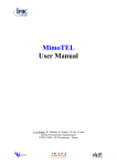
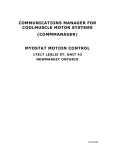
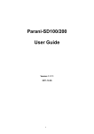
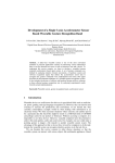
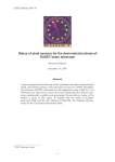
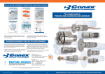
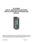
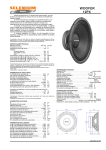
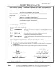
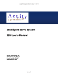
IKIMO API Manual rev.6 IKIMO Robot Controller (rev.2) User Manual Board layout and input/output connectors Notes: (Read Carefully before use) 1. Please connect Battery pack (5V or more), You can use 4 AA Alkaline/Rechargeable batteries as well. 2. Board is USB powered. Sensors and Servo motors works when connected with USB cable. No external power needed. 3. DC motors will not operate until Battery power is supplied. Written by Charith Fernando ([email protected]) IKIMO API Manual rev.6 4. When USB cable is connected, Bluetooth receive functionality is disabled. i.e any data sent from the board to PC will function, but you cannot send any data from PC to board. 5. Do not supply reverse polarity to the power port of the board. 6. Sensor interface and servo’s are provided with a +5V VCC and GND bus. IKIMO Library for use with Arduino Available pin mappings DC1_PWM – DC Motor 1 PWM Pin DC2_PWM – DC Motor 2 PWM Pin DC3_PWM – DC Motor 3 PWM Pin DC4_PWM – DC Motor 4 PWM Pin SERVO1_PWM – Servo Motor 1 PWM Pin SERVO2_PWM – Servo Motor 2 PWM Pin SERVO3_PWM – Servo Motor 3 PWM Pin SERVO4_PWM – Servo Motor 4 PWM Pin DC1_3_CONTROL1 – Control Signal Pin 1 of DC Motor 1 & 3 (DC motor controlling is paired) DC1_3_CONTROL2 – Control Signal Pin 2 of DC Motor 1 & 3 (DC motor controlling is paired) DC2_4_CONTROL1 – Control Signal Pin 1 of DC Motor 2 & 4 (DC motor controlling is paired) DC2_4_CONTROL2 – Control Signal Pin 2 of DC Motor 2 & 4 (DC motor controlling is paired) AN0 – Analog Input Pin 0 AN1 – Analog Input Pin 1 AN2 – Analog Input Pin 2 AN3 – Analog Input Pin 3 AN4 – Analog Input Pin 4 AN5 – Analog Input Pin 5 Written by Charith Fernando ([email protected]) IKIMO API Manual rev.6 Function Definitions ‐‐‐‐‐‐‐‐‐‐‐‐‐‐‐‐‐‐‐‐‐‐‐‐‐‐‐‐‐‐‐‐‐‐‐‐‐‐‐‐‐‐‐‐‐‐‐‐‐‐‐‐‐‐‐‐‐‐‐‐‐‐‐‐‐‐‐‐‐‐‐‐‐‐‐‐‐‐‐‐‐‐‐‐‐‐‐‐‐‐‐‐‐‐‐‐‐‐‐‐‐‐‐‐‐‐‐‐‐‐‐‐‐‐‐‐‐‐‐‐‐‐‐‐‐‐‐‐‐‐‐‐‐‐‐‐‐‐‐‐‐‐‐‐‐‐‐‐‐‐‐ void BLUETOOTH_SETUP(char btName[11], unsigned long btCurrentBaudRate, unsigned long btNewBaudRate) Use this function to initialize the Bluetooth module for a specific baud rate. Only one time requires and the settings will be saved in a non‐volatile memory. Parameters: btName – Bluetooth friendly name (10 characters max) btCurrentBaudRate – Current Baud rate of the module (115200bps is the factory default) btNewBaudRate – expected new Baud Rate after changing. ‐‐‐‐‐‐‐‐‐‐‐‐‐‐‐‐‐‐‐‐‐‐‐‐‐‐‐‐‐‐‐‐‐‐‐‐‐‐‐‐‐‐‐‐‐‐‐‐‐‐‐‐‐‐‐‐‐‐‐‐‐‐‐‐‐‐‐‐‐‐‐‐‐‐‐‐‐‐‐‐‐‐‐‐‐‐‐‐‐‐‐‐‐‐‐‐‐‐‐‐‐‐‐‐‐‐‐‐‐‐‐‐‐‐‐‐‐‐‐‐‐‐‐‐‐‐‐‐‐‐‐‐‐‐‐‐‐‐‐‐‐‐‐‐‐‐‐‐‐‐‐ void DC_MOTOR_CONTROL(int motorID, char status[4], int speed) Use this function to drive DC motors individually. Parameters: motorID – Motor ID from the IKIMO Board (1, 2, 3, 4) status – CLW, CCW, STP, BRK speed – 0 ~ 255 ‐‐‐‐‐‐‐‐‐‐‐‐‐‐‐‐‐‐‐‐‐‐‐‐‐‐‐‐‐‐‐‐‐‐‐‐‐‐‐‐‐‐‐‐‐‐‐‐‐‐‐‐‐‐‐‐‐‐‐‐‐‐‐‐‐‐‐‐‐‐‐‐‐‐‐‐‐‐‐‐‐‐‐‐‐‐‐‐‐‐‐‐‐‐‐‐‐‐‐‐‐‐‐‐‐‐‐‐‐‐‐‐‐‐‐‐‐‐‐‐‐‐‐‐‐‐‐‐‐‐‐‐‐‐‐‐‐‐‐‐‐‐‐‐‐‐‐‐‐‐‐ void SERVO_MOTOR_CONTROL(int motorID, int angle) Use this function to drive Servo motors individually. Parameters: motorID – Motor ID from the IKIMO Board (1, 2, 3, 4) angle – 0 ~ 180 ‐‐‐‐‐‐‐‐‐‐‐‐‐‐‐‐‐‐‐‐‐‐‐‐‐‐‐‐‐‐‐‐‐‐‐‐‐‐‐‐‐‐‐‐‐‐‐‐‐‐‐‐‐‐‐‐‐‐‐‐‐‐‐‐‐‐‐‐‐‐‐‐‐‐‐‐‐‐‐‐‐‐‐‐‐‐‐‐‐‐‐‐‐‐‐‐‐‐‐‐‐‐‐‐‐‐‐‐‐‐‐‐‐‐‐‐‐‐‐‐‐‐‐‐‐‐‐‐‐‐‐‐‐‐‐‐‐‐‐‐‐‐‐‐‐‐‐‐‐‐‐ Written by Charith Fernando ([email protected]) IKIMO API Manual rev.6 IKIMO API for use with Arduino IKIMO API provides a very high level command set so that users do not have to code that much when building robots. It also very useful when connecting the IKIMO board with application software and controlling the robot through PC. Command Syntax START BYTE (1 Byte) COMMAND (2 Bytes) OPTIONS (1 Byte) VALUES (3 Bytes) CR (1 Byte) Start Byte is set to : “!” Exclamation character. Example: ! DC 1 CLW CR This command will turn the DC motor 1 ClockWise rotation. Notes: 1. Each command will have a response from the IKIMO board. 2. Default Baud Rate for IKIMO API is 19200 3. If you want the IKIMO to Operate in a different BaudRate, please configure the Bluetooth first using the following command (more details please refer IKIMO Library Functions) BLUETOOTH_SETUP(char btName[11], unsigned long btCurrentBaudRate, unsigned long btNewBaudRate) 4. Please make sure you send at‐least 7 bytes with Carriage Return(CR) in order to get the correct response from the board. Anything less than 7 bytes, the IKIMO Board will not respond. 5. If you send more than 7 charactors, excess will be discarded. 6. IKIMO will issue an error message if the command or the options are not correct. Written by Charith Fernando ([email protected]) IKIMO API Manual rev.6 COMMAND SET (API LEVEL 1) 1.
DC Motor driving START BYTE (1 Byte) COMMAND (2 Bytes) OPTIONS (1 Byte) VALUES (3 Bytes) CR (1 Byte) ! DC 1, 2, 3, 4 CLW, CCW, STP, BRK CR Note: 1. 1, 2, 3, 4 denotes the Motors connected to the DC PORT 1‐4 Example: !DC1CLW Response DC_MOTOR1:FWD:230 (230 is the current speed) 2.
Servo Motor driving START BYTE (1 Byte) COMMAND (2 Bytes) OPTIONS (1 Byte) VALUES (3 Bytes) CR (1 Byte) ! SV 1, 2, 3, 4 Angle (0 ~ 180) CR Note: 1. 1, 2, 3, 4 denotes the Motors connected to the SERVO PORT 1‐4 2. Values written to Angle should be of 3 characters. For example 90 Degrees should be entered as 090. Example: !SV1180, !SV2090 Response SERVO_MOTOR1:180 (180 is the current angle) Written by Charith Fernando ([email protected]) IKIMO API Manual rev.6 3.
DC Motor Speed setting / Rotational Speed START BYTE (1 Byte) COMMAND (2 Bytes) OPTIONS (1 Byte) VALUES (3 Bytes) CR (1 Byte) ! SP G, 1, 2, 3, 4, R Speed (0 ~ 255) CR Note: 1. G denotes Global speed, 1, 2, 3, 4 denotes individual motor speeds, R denotes rotational speed. 2. Values written to Speed should be of 3 characters. For example 50 should be entered as 050. 3. Values written to the Speed will remain in the program until a complete restart or power Shutdown. Example: !SPG100, !SV2090 Response: Global Speed: 100 4.
Analog Port reading START BYTE (1 Byte) COMMAND (2 Bytes) OPTIONS (1 Byte) VALUES (3 Bytes) CR (1 Byte) ! AN 0, 1, 2, 3, 4, 5 ?RD/?WR CR Note: 1. Analog Write is currently unavailable. 2. 0, 1, 2, 3, 4, 5 denotes the analog ports available in the board. Example: !AN0?RD Response: AN0: 567 (0 ~ 1023) Written by Charith Fernando ([email protected]) IKIMO API Manual rev.6 COMMAND SET (API LEVEL 2) In API Level 2, We consider the board to be used with a robot platform and provides basic functionality such as move forward, backward, rotate etc….You should not use the API Level 2, if you are not planning to build a robot using IKIMO Robot Controller board. For a 2 wheel robot, please use DC PORT 1, 2 only. Make sure to connect the Polarity of the DC motor correctly to the IKIMO Board. 1.
Robot Move commands (Forward/Backward) START BYTE (1 Byte) COMMAND (3 Bytes) VALUES (3 Bytes) CR (1 Byte) ! FWD, REV Speed (0 ~ 255) CR Note: 1. Works with 2 wheel and 4 wheel versions. 2. FWD – Forward and REV ‐ Reverse 3. In this command the Global Speed doesn’t count. Example: !FWD150, !REV050 Response: MOV‐FWD: 150, MOV‐REV: 50 2.
Robot Rotate (Left/Right) START BYTE (1 Byte) COMMAND (3 Bytes) VALUES (3 Bytes) CR (1 Byte) ! RTL, RTR Angle (0 ~ 360), >360 CR Note: 1. Works with 2 wheel and 4 wheel versions. 2. Angle is not so precise. 3. RTL – Rotate Left, RTR Rotate Right 4. If value of the angle is >360 it will be a continuous rotation. Written by Charith Fernando ([email protected]) IKIMO API Manual rev.6 5. Use SPR??? for changing the rotational speed. Example: !RTL090, !RTR400 Response: ROT‐LEFT: 90, ROT‐CONT 3.
Robot Steering (Left/Right) START BYTE (1 Byte) COMMAND (3 Bytes) VALUES (3 Bytes) CR (1 Byte) ! STL/STR Steering Value (0 ~ 100) CR Note: 1. Increases and decreases the speed of left and right so that a balanced steering will occur. 2. Steering speed + global speed < 255 and global speed ‐ steering speed > 0 3. To use after FWD, REV commands only. Example: !STR050 Response: Steer‐RIGHTT: 50 4.
Robot Brake/Stop START BYTE (1 Byte) COMMAND (3 Bytes) VALUES (3 Bytes) CR (1 Byte) ! BRK, STP Delay before Brake (ms) CR Note: 1. BRK – Brake, STP – Stop 2. Value should be time to break. i.e if the brake or stop is instant please use 000 as the value. Written by Charith Fernando ([email protected]) IKIMO API Manual rev.6 Example: !BRK000 Response: BRAKE:0 5.
Read Accelerometer data START BYTE (1 Byte) COMMAND (3 Bytes) VALUES (3 Bytes) CR (1 Byte) ! ACC RDX, RDY, RDZ, RDA CR Note: 1. Read X, Read Y, Read Z and Read all can be found for the valid arguments. Example: !ACCRDX Response: KXM52‐X: 1.39mg (measurement in Milli G) 6.
Read Distance data START BYTE (1 Byte) COMMAND (3 Bytes) VALUES (3 Bytes) CR (1 Byte) ! DIS ?RD CR Note: 1. Read the distance to the nearest obstacle. Example: !DIS?RD Response: GP2Y distance: 48mm (measurement in Millimeters) Written by Charith Fernando ([email protected]) IKIMO API Manual rev.6 7.
Read Bend Sensor data START BYTE (1 Byte) COMMAND (3 Bytes) VALUES (3 Bytes) CR (1 Byte) ! BND ?RD CR Note: 1. Read the bending of the sensor arm. Example: !BND?RD Response: FS22 Bend: 1.07V (measurement in Volts) Written by Charith Fernando ([email protected]) IKIMO API Manual rev.6 IKIMO sensor connection guide GND +5V
Signal
Here is the pin out of sensor port. Each port is provided with 5V and GND connections so that most analog sensors can be directly connected to the IKIMO board. Examples: Accelerometer KXM 52: Connection Map chart KXM 52 1 (VDD) 2 (PSD) 3 (GND) 4 (Parity) 5 (Self Test) 6 X‐Out 7 Y‐Out 8 Z‐Out IKIMO Board
AN0 Port Vdd
AN0 Port Vdd
AN0 Port GND
N/A AN0 Port GND
AN0 Port Signal
AN1 Port Signal
AN2 Port Signal
Written by Charith Fernando ([email protected]) IKIMO API Manual rev.6 GP 2Y Distance sensor: Here is a sample for connecting to Arduino. Same as above use the conversion chart below to connect to IKIMO. Connection Map chart GP2Y 1 RED wire (Vdd)
2 Black wire (GND) 3 Yellow wire (Signal) IKIMO Board
AN0 Port Vdd
AN0 Port GND
AN0 Port Signal
Written by Charith Fernando ([email protected]) IKIMO API Manual rev.6 Bend Sensor: Bend sensor changes it’s resistance when it bends. With that specification, bending can be detected by attaching the bend sensor into a resistor voltage divider and by measuring the voltage. Connect an external resistor as above. Connection Map chart Flex Sensor 1 +5V 2 GND 3 Arduino Analog
IKIMO Board
AN0 Port Vdd
AN0 Port GND
AN0 Port Signal
Written by Charith Fernando ([email protected]) IKIMO API Manual rev.6 IKIMO Schematic files Written by Charith Fernando ([email protected])