1
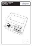
Capative voltage detecting system User manual Document version: Update: 01i00 2015-03-13 Safety information When the device is in operation some of its parts may be connected to a hazardous live voltage. Improper operation of the device or its application to purposes different from the intended use may pose hazards to operators and /or may lead to the equipment damage. National and local electrical safety regulations must always be followed. The user shall be held fully responsible for any safety risk and possible failures of the equipment that may arise due to such an improper operation or misuse. Exploration of damaged device can result in malfunction of protected object and result in threat to life and health. Reliable and defect-free operation of the device needs appropriate transportation, handling, storage, installation and commissioning as well as correct operation and maintenance. The device can be installed and operated solely by accordingly trained personnel. Attention We reserve the right to modify the device. Device is an industrial monitoring and control instrument. Remaining user documentation can be downloaded from energetyka.itr.org.pl User manual Contents: 1. Introduction ............................................................................................................................................ 4 1.1. Symbols .............................................................................................................................................. 4 2. General Information ................................................................................................................................ 5 2.1. Destination of the equipment.............................................................................................................. 5 2.2. Features .............................................................................................................................................. 6 2.3. Front panel.......................................................................................................................................... 7 2.4. Optical signaling .................................................................................................................................. 7 3. Operation manual.................................................................................................................................... 8 4. List of referred standards ......................................................................................................................... 9 5. Technical parameters............................................................................................................................. 10 5.1. Input/outputs circuits ........................................................................................................................ 10 5.2. Power supply..................................................................................................................................... 10 5.3. Environmental conditions .................................................................................................................. 10 5.4. Construction ..................................................................................................................................... 11 5.5. Fuse .................................................................................................................................................. 11 6. Connector description ........................................................................................................................... 12 7. Application schematic ............................................................................................................................ 13 8. Dimensions............................................................................................................................................ 14 9. Remarks of manufacturer ...................................................................................................................... 15 9.1. Maintenance, inspections, repairs ..................................................................................................... 15 9.2. Storage and transport........................................................................................................................ 15 9.3. Place of installation ........................................................................................................................... 15 9.4. Disposal ............................................................................................................................................ 15 9.5. Warranty and service ........................................................................................................................ 16 10. Order specification ................................................................................................................................ 17 11. Contact.................................................................................................................................................. 18 IU_SN4_MANUAL_01i00_ENG Page 3 z 18 User manual 1. Introduction 1.1. Symbols Electrical warning symbol indicates the presence of hazardous energy circuits or electric shock hazards. The warning symbol indicates the important information related to the threat to life and health. The information symbol indicates the clarification of relevant features and parameters of the device. Page 4 z 18 IU_SN4_MANUAL_01i00_ENG User manual 2. General Information 2.1. Destination of the equipment Device SN 4 is designed for a continuous voltage signalization on in MV grids. Fig. 2.1.1 The view of SN 4 SN 4 is provided with two relay outputs and two LED diodes signaling the lack of voltage in MV grids. This allows to construct local blocking and sound device signaling voltage restoration. The voltage presence is indicated separately for every monitored phase as a displayed symbol . The device is made to the requirements of the LRM system - standard IEC/PN-EN 61243-5. Connection with current buses over reactance insulators. SN 4 is provided with a protection flap to block direct access to the front panel. During normal operation the protection flap should be closed. It shall be opened only for measurements; with measurements complete close the flap again. IU_SN4_MANUAL_01i00_ENG Page 5 z 18 User manual 2.2. Features Case small dimensions 125.5 / 55,7 / 50 mm flush-mounted User interface 3 signaling diodes: ON - red diode, voltage presence, OFF - orange diode, no voltage, 3 symbols signaling voltage presence on each monitored phase - supply Signalization Two relay outputs (contact, switch-over): voltage at one of monitored phases no voltage at monitored phases Voltage presence at each of monitored phases - a lighted signal signal on the LCD display: voltage present at each monitored phase - signaled by lighted red diode no voltage on monitored lines as lighted orange diode Page 6 z 18 ON OFF IU_SN4_MANUAL_01i00_ENG User manual 2.3. Front panel Fig. 2.3.1. Front panel view On the front panel there are: 1) Diode signaling the supply voltage 2) Diode signaling the voltage presence 3) Diode signaling no voltage present 4) LCD display 5) LRM connector 2.4. Optical signaling Tab. 2.4.1. Meaning of predefined diodes: Symbol/Name Color green ON red OFF orange black Description signals feeding of correct supply voltage to the device continuous light signaling voltage presence on one line signaling no voltage present signaling voltage presence on a given line In case in a space where the device is operating there is a strong solar radiation in order to read the signaling bet it can be necessary to manually dim the LCD display better. IU_SN4_MANUAL_01i00_ENG Page 7 z 18 User manual 3. Operation manual SN 4 is designed for continuous voltage signalization in MV grids. It checks three phase voltages and signals the presence of each of them. It is provided with two binary voltage less outputs (contact, switch-over). The binary output DO_1 serves for signaling the lack of voltage on monitored lines. The binary output DO_1 serves for signaling the presence of voltage on monitored lines. On the front plate there are three diodes signaling operation of the device orange diode , no voltage on monitored lines, OFF and voltage on at least one of monitored lines, red diode lighted symbol ply). ON. On the LCD display a means no voltage or voltage presence on each monitored phase (this signal needs not sup- Signaling presence or lack of voltage at binary outputs and LED diodes requires voltage supply connected to the device. Tab. 3.1. Operation signaling: LCD signaling L1 L2 LED signaling L3 lack of voltage (OFF diode) voltage presence (ON diod) Binary output lack of voltage DO_1 Phase voltage voltage presence DO_2 L1 ● ● L2 L3 ● ● ● ● Page 8 z 18 ● ● ● ● ● ● ● ● IU_SN4_MANUAL_01i00_ENG User manual 4. List of referred standards The device described in this manual has been designed and is manufactured for industrial applications. The engineering and manufacturing processes assumes compliance with relevant standards. Adherence to these standards during installation, commissioning and operation of the device by the user is the essential precondition to achieve the desired performance and safety levels. The device meets essential requirements specified in the applicable EU Directives: Electromagnetic compatibility (EMC) 2004/108 / EC Low-voltage electrical equipment (LVD) 2006/95 / EC Tab. 4.1. Harmonized standards No. standards PN-EN 61000-6-2:2008 Title of the standard Electromagnetic compatibility (EMC). PN-EN 61010-1:2011 PN-EN 61243-5:2004 Safety requirements for electrical equipment for measurement, control, and laboratory use. General requirements Live working. Voltage detectors. Voltage detecting systems (VDS) PN-EN 60529:2003 Specification for degrees of protection provided by enclosures (IP code). IU_SN4_MANUAL_01i00_ENG Page 9 z 18 User manual 5. Technical parameters 5.1. Input/outputs circuits Voltage input circuits Number of inputs Minimal voltage threshold, LCD signaling Minimal voltage threshold, LED, relay signaling Voltage hysteresis of the LED signaling Input capacity Maximum length of the connected cables Binary outputs Switching capability at resistance load Contacts material Maximum length of the connected cables 5.2. 2 250 V AC, 5 A 30 V DC, 5 A 250V DC, 0.1 A 1250 VA AgNi < 3m Power supply Nominal voltage Power consumption Resistance to voltage dump 5.3. 3 3.4 V rms +-0.2V 3.4 V rms +-0.2V 0.05 V rms 1500 pF + matching capacitor < 3m 24 V -20% +10% <1W 10 ms Environmental conditions Temperature operational Temperature storage Air humidity Class equipment Overvoltage category Electrical environment Pollution degree Mechanical tests Sinusoidal vibration Single and multiple shocks and bumps Seismic Installation Page 10 z 18 -25˚C … +55˚C -35˚C … +85˚C lack of condensation and frost deposition 0 III B 2 class 1 class 1 class 0 indoor IU_SN4_MANUAL_01i00_ENG User manual 5.4. Construction Mass Dimensions (width, height, depth) Degree of protection Front panel side Connector side with connectors plugged Connector Type Connection wires Stripping length Housing mounting 5.5. < 0,5 kg 125.5 / 55,7 / 50 mm IP 54 IP 30 Wago 254-454 Wago 734-138 not exposed to corrosion Cable stranded 0,5...2mm2 (end sleeve) 2 Cable solid 0,5...2.5mm 10 .. 12mm flush-mounted Fuse Mounted internal fuse IU_SN4_MANUAL_01i00_ENG FRN01WK0100A10 Select these according to general rules so that operation at exceeded rated levels at individual paths is not possible. Page 11 z 18 User manual 6. Connector description Tab. 6.1. Connector X1 Terminal No. Designation 1 L1 2 L2 3 L3 4 PE Description / Purpose phase L1 phase L2 phase L3 common for L1,L2,L3 (Earth PE) Tab. 6.2. Connector X2 Terminal No. 1 2 3 4 5 6 7 8 Designation DC/DC DO_1 DO_2 Description / Purpose Power supply 24 VDC ( plus ) Power supply 24 VDC ( minus ) Output 1 - lack of voltage -normally closed contact Output 1 - lack of voltage -normally opened contact Output 1 Output 2 - presence of voltage -normally closed contact Output 2 - presence of voltage -normally opened contact Output 2 Fig. 6.1. The view of connectors site. The red dot on the connector is the first pin of the terminal. Page 12 z 18 IU_SN4_MANUAL_01i00_ENG User manual 7. Application schematic Fig. 7.1. Connection diagram IU_SN4_MANUAL_01i00_ENG Page 13 z 18 User manual 8. Dimensions Fig. 8.1. Dimensions Page 14 z 18 IU_SN4_MANUAL_01i00_ENG User manual 9. Remarks of manufacturer 9.1. Maintenance, inspections, repairs The manufacturer recommends that correctness of device operation is verified: a) each time - during commissioning, b) at least once a year - in mine face installations, c) at least once every 5 years in installations other than front face. Also inspections resulting from branch regulations should be undertaken. 9.2. Storage and transport Devices are packed in transport packages and secured against damage during transport and storage. Devices should be stored in transport packages, indoors, in places free from vibrations and direct effects of weather conditions, dry, well ventilated, free from harmful vapors and gases. Ambient air temperature should be between –35°C and +85°C, and relative humidity should not exceed 80%. All shipped devices are attached with complete set of connectors, grounding braid, warranty card and quality certificate. 9.3. Place of installation SN 4 device is designed to installation in the mounting hole with dimensions of 85 mm x 35 mm at the door of the indoor power distribution stations. Length of single cable connected to device sockets cannot 3 m. Installation of the device: insertion the device into the mounting hole tighten the set screws to the surface of the door 9.4. Disposal Devices are made mostly from recyclable materials, or materials that can be processed again or disposed of in environmentally sound manner. Decommissioned devices can be collected for recycling, provided that their condition is that of normal wear and tear. All components that are not recyclable shall be disposed of in environmentally sound manner. IU_SN4_MANUAL_01i00_ENG Page 15 z 18 User manual 9.5. Warranty and service Regular 36-month guarantee period. Had the sale been preceded by execution of an Agreement between the Buyer and the Seller, provisions of such Agreement shall apply. Guarantee covers remedying of defects, free of charge, provided that instructions specified in the Warranty Card are adhered to. Detailed guarantee conditions may be found at energetyka.itr.org.pl in the w „Sale Regulations”. The guarantee period is counted from the date of sale. The warranty is extended by a period of residence of the product in the repair. Unauthorized tampering with the product will void the warranty. Warranty does not cover damage resulting from improper use of the product. Page 16 z 18 IU_SN4_MANUAL_01i00_ENG User manual 10. Order specification SN4 A matching capacitor: 0 = lack 1 = 47 nF 2 = 100 nF 3 = 150 nF 4 = 4.7 nF 5 = 10 nF 6 = 22 nF Order example: SN4: A1 SN4: A2 - matching capacitor 47 nF - matching capacitor 100 nF In the case of the order specifications higher than A0 device on the lines L1, L2, and L3 is additionally installed Gas Discharge Tube. At the customer's request can be not installed. Other versions after consultation with the manufacturer. IU_SN4_MANUAL_01i00_ENG Page 17 z 18 User manual 11. Contact Instytut Tele- i Radiotechniczny Centrum Teleinformatyki i Elektroniki 03-450 Warszawa, ul. Ratuszowa 11 Poland tel./faks: + 48 22 619 73 14 e-mail: [email protected] www: energetyka.org.pl Page 18 z 18 IU_SN4_MANUAL_01i00_ENG