1
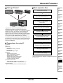
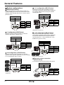
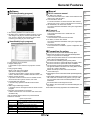
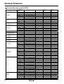
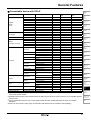
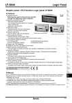
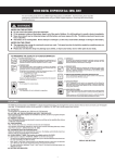
General Features
GP(Graphic Panel)?
Advantages of using GP
Complicated environment of operation
and control
It graphicalizes mechanical control components such as
button, switch and lamps so that saves cost and space and
improves the preservation of devices.
GP-S044
GP-S070
GP-S057
Graphic panel is HMI(Human Machine Interface) device
that parameter monitors or changes via graphic interface
by communication with PLC, temperature controller or
other control units.
Graphic interface of GP is very effective to indicate value
or status of parameter with visual interface that enables the
communication between controller and user.
GP is able to monitor parameters virtually with LCD
screen, switch screen by touching screen, set or change
parameters. GP connecting with controller via serial
communication method translates data and displays
various control parameters with graphic.
For example, in case of the target of parameters is the
temperate, the numerical value of temperature is shown
with a tag and the change in temperature for time can be
graphed on the screen.
Control part
GP-S044
Control part
GP-S044
Setting and change of production
process
It graphicalizes mechanical control components such as
button, switch and lamps so that saves cost and space and
improves the preservation of devices.
Alarm is
occurred.
Alarm alert,
Preservation of history
PLC
Convenient setting by user
Preparation for using GP
The numerical value
of temperature
GP-S044
It sets complicated or non-displaying controller
(Thermometer/hygrometer, temperature controller etc).
1)Temperature/Humidity without display device
RS485
Graph of temperature
1) GP body
2) PC
3) GP Editor
- Software for drawing GP screen
4) Manual
- GP editor user manual
- LP, GP Communication manual
- GP-S044/S057, GP-S070 user manual
5) Communication cable
- Communication cable for PC connection
- Communication cable for controller connection
6) Access devices
(PLC or controller built in communication ports)
Display temperature,
humidity
2)Temperature controller
RS485
#1...........#32
Effective data control
Easy to set and
adjust parameter.
It prints alarm history of controller using printer. It reads the
data from barcode reader and save it in PLC.
1)PLC/Printer
Basic operation flow
Requirements
for using GP
Install GP Editor
on PC
Design data
with GP Editor
<Refer to GP editer
user manual>
Download display
data to GP
PLC
2)Barcode reader/PLC
GP-S044
Printer
Connection between
PC and GP body
<Refer to GP, LP
communication manual>
GP connect device
GP-S044
PLC
Communication between heterogeneous
controllers
<Refer to GP, LP
communication manual>
Start monitoring
R-2
PLC
GP-S044
Thermometer/
hygrometer
General Features
LP(Logic Panel)?
Basic operation flow
(A)
Photo
electric
sensor
Requirements for using LP
HMI
I/O
PLC
(B)
Fiber
optic
sensor
<Refer to GP editer user manual and SmartStudio>
(C)
Door/Area
sensor
Install drawing program (GP Editor) and
logic program (Smart Studio) on PC
(D)
Proximity
sensor
<Refer to communication manual>
(E)
Pressure
sensor
Connection PC with LP body
※When LP turns on, RUN/STOP switch holds
STOP position.
(F)
Rotary
encoder
<Refer to the SmartStudio programming manual>
LP-S044
LP-S070
Logic panel is created for integrated panel in most
demanding industrial environments that have been
consisted of HMI, PLC and I/O. The LP through integration
realizes cost down, wire reduction, space saving and
enhanced user friendliness. The logic panel perfectly
supports serial communication and editing display with GP
Editor and about 250 commands of SmartStudio invented
on our own to edit PLC ladder/mnemonic, allowing
accelerating product development and designing. And also
this device can control and monitor various output devices
(sensors, button, etc) and output devices (solenoid, lamp,
motor, etc) individually.
Preparations for using LP
1) LP body
2) PC
3) Software
① GP Editor
- Software for drawing LP screen
② SmartStudio
- Software for logic program
4) Manual
- GP Editor user manual
- GP,LP Communication manual
- SmartStudio user manual
- SmartStudio programming manual
- LP-S044, LP-S070 user manual
- LP series command manual
5) Communication cable
- Communication cable for PC connection
- Communication cable for controller connection
6) Access device
(PLC or controller built in communication ports)
(G)
Connector/
Socket
Make Logic program with SmartStudio
(H)
Temp.
controller
Download logic data to LP body
(I)
SSR/
Power
controller
Disconnect Smart Studio with LP body/
Connect GP Editor with LP body
(J)
Counter
(K)
Timer
Create screen or download to LP body
(L)
Panel
meter
Test
※RUN/STOP switch holds RUN position.
(M)
Tacho/
Speed/ Pulse
meter
(N)
Display
unit
Debugging or editing program
(O)
Sensor
controller
Control or start monitoring
※Refer to the manual for details on website(www.autonics.
com) resources.
(P)
Switching
mode power
supply
(Q)
Stepper
motor&
Driver&Controller
(R)
Graphic/
Logic
panel
(S)
Field
network
device
(T)
Production
stoppage models
& replacement
(U)
Other
R-3
General Features
System configurations
1:1:1 configuration (GP/LP Series)
Stand alone(LP Series)
Stand alone system in LP series controls a variety of I/
O without adding other devices and monitors and control
operation element through direct touch of screen. (device,
parameter, etc.)
The device function makes it possible to monitor,
control and the operation element (device, parameter,
etc.) between different devices using two separate
communication port.
PC
GP Editor
PC
SmartStudio
GP Editor
Drawing data Logic program
Download/
upload data
Run
Stop
SmartStudio
Drawing data Control program
Download/
upload data
Input device
Button
Limit switch
Sensors
Other input
devices
Output device
Solenoid
Lamp
Motor
Other output
devices
A Controls
(PLC type)
Stop
Run
Input device
Button
Limit switch
Sensors
Other input
devices
Output device
Solenoid
Lamp
Motor
Other output
devices
B Controls
(Temperature controller, etc)
1:1 configuration (LP/GP Series)
The device function makes it possible to monitor the
operation data (Device, parameter, etc.)
PC
GP Editor
SmartStudio
1:1 N configuration (GP/LP Series)
The device function makes it possible to monitor,
control and the operation element (device, parameter,
etc.) between different devices using two separate
communication port.. In case of RS-422 port, 1:N is
available only. (Up to 31 units).
Drawing data Control program
PC
Download/
upload data
Run
Stop
Input device
Button
Limit switch
Sensors
Other input
devices
Output device
Solenoid
Lamp
Motor
Other output
devices
GP Editor
SmartStudio
Drawing data Control program
Download/
upload data
Controls(PLC type)
A Controls(PLC type)
#1..................#31
1:N configuration (LP/GP Series)
The device function makes it possible to monitor the
operation element (device, parameter, etc.) by connecting
in a 1:N configuration (Up to 32 units)
GP Editor
SmartStudio
·
·
·
#31
Controls
(Temperature
controller, etc)
B Controls
(Temperature controller, etc)
It can read bar-code and print a history using printer.
Drawing data Control program
#2
PC
Download/
upload data
Run
Stop
Input device
Button
Limit switch
Sensors
Other input
devices
Output device
Solenoid
Lamp
Motor
Other output
devices
GP Editor
SmartStudio
Drawing data Control program
Download/
upload
data
Bar-code deader
Run
Serial printer
R-4
Output device
Solenoid
Lamp
Motor
Other output
devices
Bar-code, printer connection
(GP/LP Series)
PC
#1
Stop
Run
Input device
Button
Limit switch
Sensors
Other input
devices
Stop
Input device
Button
Limit switch
Sensors
Other input
devices
Output device
Solenoid
Lamp
Motor
Other output
devices
General Features
Software
GP Editor(Drawing program)
Manual
(A)
Photo
electric
sensor
GP/LP common manual
● GP Editor user manual
This section describes how to make screen data and use
HMI function with GP Editor.
● Communication manual
For more information of serial connection with external
devices such as PLC, refer to manual before connecting.
● GP-S044/S057, GP-S070 user manual
The manual describes installation and system organization
and menus.
LP manual
● This drawing software is for GP/LP series.
● GP Editor is the software that allows creating a screen
and designs a tag layout, and then transfer the data
from screen to GP/LP. After download, GP/LP starts
monitoring according to your screen data.
SmartStudio(Logic program)
● SmartStudio manual
This section describes how to install and use
SmartStudio.
● Programming manual
The manual has command and instruction.
● LP-S044, LP-S070 user manual
The manual describes installation and system organization
and menus.
● LP Series instruction manual
The manual has LP installation, system configuration and
instruction.
Precaution for using
● Logic software is for LP series.
● Support multi-project
: It is possible to open maximum 5 projects at a same
time.
● Easy program editing
: Block of cell units can be edited.
Split-screen editing is available.
It provides various editing screens such as variable
screen, describe screen, variable /describe screen, etc,.
● Various monitor functions
: It provides monitor functions such as variable monitor,
device monitor and system monitor, time chart.
● Comfortable user interface
: It ensures easy operation with Microsoft windows
layout.
● Wide range of Message windows
: It supports various message windows to edit and check
program.
● Real time convert ladder to mnemonic
: Ladder and mnemonic can be written and read to edit
simultaneously.
Visit our website (www.autonics.com) and download
software or manuals.
Do not press touch panel with hard and sharp object.
Please store the device in the recommended temperature
range, or LCD panel can be damaged.
Please check pin number shown in "Communication manual"
when connect communication port
Do not block the ventilating opening of this product.
Do not use or store it in a place with direct ray of light or dust.
Do not use or store it in a place with shock or vibration.
The ground wire of GP/LP should be grounded separately.
The ground resistance should be max. 100Ω, please use the
wire of min. 1.25mm² dimension.
Please check the pin number and connect to GP/LP
communication port.
Please tighten bolt on terminal block with specified tightening
torque.
When liquid crystal from the broken LCD is smeared on your
skin, wash it for 15 minutes. If it is gotten in your eye, wash
it for 15 minutes and contact a medical specialist for more
information.
Do not inflow dust or wire dregs into the unit.
For cleaning, do not use water or an oil-based detergent, use
dry towels.
It should be done away regarded as an industrial waste.
(B)
Fiber
optic
sensor
(C)
Door/Area
sensor
(D)
Proximity
sensor
(E)
Pressure
sensor
(F)
Rotary
encoder
(G)
Connector/
Socket
(H)
Temp.
controller
(I)
SSR/
Power
controller
(J)
Counter
(K)
Timer
(L)
Panel
meter
(M)
Tacho/
Speed/ Pulse
meter
(N)
Display
unit
(O)
Sensor
controller
(P)
Switching
mode power
supply
(Q)
Stepper
motor&
Driver&Controller
(R)
Graphic/
Logic
panel
(S)
Field
network
device
(T)
Production
stoppage models
& replacement
< System requirements >
Item
Minimum requirements
IBM PC compatible computer with Intel Pentium
System
Ⅲ or above
Operating system Microsoft Windows 98/NT/XP/Vista/7
Memory
256MB or more
Hard disk
More than 1GB of free hard disk space
VGA
1024×768 or higher resolution display
Others
RS-232 serial port(9-pin), USB port
(U)
Other
R-5
General Features
Connectable device with GP/LP
Series
LS Master-K
LS Glofa
LS CNET
(Cnet integrated CPU)
LS CNET
(For Cnet unit)
LS XGT(For Cnet unit)
LS XGB
(Cnet integrated CPU)
LS XGB
(For Cnet unit)
OEMAX
(SAMSUNG)
OEMAX FARA
MITSUBISHI FX
MITSUBISHI Q
(For Cnet unit)
NAIS FP
SIEMENS
SIMATIC
S7-200
R-6
Connectable
device
Connection type
GP-S057
GP/LPS044
GP/LPS070
MK-10S1
MK-80S
MK-120S
MK-200S
MK-300S
MK-1000S
GM4
GM6
GM7U
MK-80S
MK-120S
MK-200S
MK-80S
MK-120S
MK-200S
MK-300S
MK-1000S
XGK- PUS
XBM
XBC
XBM
XBC
N70
N70Plus
NX7
NX70
FX1S
FX1N
FX2N
FX2NC
FX3U
Q00J
Q00
Q01
Q02
Q02H
Q06H
Q12H
Q25H
FP0-C10
FP0-C14
FP0-C16
FP0-C32
FPG- C24R2
FPG- C32T
FPG- C32T2
FP0R-C10
FP0R-C14
FP0R-C1
FP0R-C32
FP0R-T32
FP0R-F32
CPU221
CPU222
CPU224
CPU224XP
CPU224XPsi
CPU226
CPU direct connection loader
CPU direct connection loader
CPU direct connection loader
CPU direct connection loader
CPU direct connection loader
CPU direct connection loader
CPU direct connection loader
CPU direct connection loader
CPU direct connection loader
Cnet
Cnet
Cnet
Cnet
Cnet
Cnet
Cnet
Cnet
Cnet
Cnet
Cnet
Cnet
Cnet
Cnet
Cnet
CPU direct connection loader
CPU direct connection loader
CPU direct connection loader
CPU direct connection loader
CPU direct connection loader
CPU direct connection loader
CPU direct connection loader
Cnet
Cnet
Cnet
Cnet
Cnet
Cnet
Cnet
Cnet
CPU direct connection loader
CPU direct connection loader
CPU direct connection loader
CPU direct connection loader
CPU direct connection loader
CPU direct connection loader
CPU direct connection loader
CPU direct connection loader
CPU direct connection loader
CPU direct connection loader
CPU direct connection loader
CPU direct connection loader
CPU direct connection loader
CPU direct connection loader
CPU direct connection loader
CPU direct connection loader
CPU direct connection loader
CPU direct connection loader
CPU direct connection loader
○
○
○
○
○
○
○
○
○
○
○
○
○
○
○
○
○
○
○
○
○
○
○
○
○
○
○
○
○
○
○
○
○
○
○
○
○
○
○
○
○
○
○
○
○
○
○
○
○
○
○
○
○
○
○
○
○
○
○
○
○
○
○
○
○
○
○
○
○
○
○
○
○
○
○
○
○
○
○
○
○
○
○
○
○
○
○
○
○
○
○
○
○
○
○
○
○
○
○
○
○
○
○
○
○
○
○
○
○
○
○
○
○
○
○
○
○
○
○
○
○
○
○
○
○
○
○
○
○
○
○
○
○
○
○
○
○
○
○
○
○
○
○
○
○
○
○
○
○
○
○
○
○
○
○
○
○
○
○
○
○
○
○
○
○
○
○
○
○
○
○
○
○
○
General Features
Connectable device with GP/LP
Series
SIEMENS
SIMATIC
S7-300
Allen-Bradley
OMRON SYSMAC C
OMRON
Temperature controller
Connectable device Connection type
GP-S057
GP/LPS044
GP/LPS070
CPU312
CPU direct connection loader
○
○
○
CPU312C
CPU313C
CPU313C-2
CPU314
CPU314C-2
CPU315-2
CPU317-2
CPU319-3
MicroLogicx 1000
MicroLogicx 1200
MicroLogicx 1500
CPM 1A
E5AN
E5AR
E5CN
E5EN
E5ER
CPU direct connection loader
CPU direct connection loader
CPU direct connection loader
CPU direct connection loader
CPU direct connection loader
CPU direct connection loader
CPU direct connection loader
CPU direct connection loader
CPU direct connection loader
CPU direct connection loader
CPU direct connection loader
CPU direct connection loader
Modbus
Modbus
Modbus
Modbus
Modbus
Private communication
Modbus
Modbus(TYPE A)
Private communication
Modbus
Modbus(TYPE A)
Private communication
Modbus
Modbus(TYPE A)
Modbus
Modbus(TYPE A)
Modbus
Modbus(TYPE A)
Modbus(TYPE A)
Modbus(TYPE A)
○
○
○
○
○
○
○
○
○
○
○
○
○
○
○
○
○
○
○
○
○
○
○
○
○
○
○
○
○
○
○
○
○
○
○
○
○
○
○
○
○
○
○
○
○
○
○
○
○
○
○
○
○
○
○
○
○
○
○
○
○
○
○
○
○
○
○
○
○
○
○
○
○
○
○
○
○
○
○
○
○
○
○
○
○
○
×
○
○
×
○
○
×
○
×
○
×
○
○
○
○
○
Modbus
○
○
×
Modbus(TYPE A)
○
○
○
Modbus
KRN50
Modbus(TYPE A)
Modbus
DTB Series
Modbus(TYPE A)
Modbus
FC Series
Modbus(TYPE A)
UNIVERSAL
Modbus(Slave)
MODBUS MASTER Modbus(Master)
○
○
○
○
×
○
○
○
○
○
○
○
×
○
○
○
×
○
×
○
×
○
○
○
MT Series
MP Series
THD Series
TZ Series
AUTONICS
TK Series
TM Series
CT Series
DS/DA Series
ARM Series
LP-S044,
LP-S070
DPU Series
KONICS
DELTA
DANFOSS
UNIVERSAL
MODBUS MASTER
CPU
(A)
Photo
electric
sensor
(B)
Fiber
optic
sensor
(C)
Door/Area
sensor
(D)
Proximity
sensor
(E)
Pressure
sensor
(F)
Rotary
encoder
(G)
Connector/
Socket
(H)
Temp.
controller
(I)
SSR/
Power
controller
(J)
Counter
(K)
Timer
(L)
Panel
meter
(M)
Tacho/
Speed/ Pulse
meter
(N)
Display
unit
(O)
Sensor
controller
(P)
Switching
mode power
supply
(Q)
Stepper
motor&
Driver&Controller
(R)
Graphic/
Logic
panel
※GP/LP connectable device list will keep updated according to the upgrade of GP Editor or additional patch. It is recommended to
use the latest version of Editor.
※Applicable GP/LP firmware version is determined by GP Editor version. Whole GP system goes down if non-compatible firmware
version is used.
※Visit our website (www.autonics.com) to check update of latest GP Editor and GP/LP firmware and to get more detailed
instructions.
※Refer to the user manual to select proper communication cable between GP and controllers. (Sold separately)
R-7
(S)
Field
network
device
(T)
Production
stoppage models
& replacement
(U)
Other