1
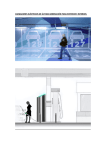
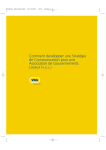
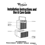
PO Box 3125 STN LCD1 Langley, BC Canada V3A 4R5 604.534.4696 (phone) 604.534.3674 (facsimile) 1.866.534.4696 (toll free North America) [email protected] (email) www.directdryers.com (web address) XXXX XXXX XXXXXX XXXXXX PPE Series EOD Suit Direct Dryers™ User Manual ©2011 Williams® Direct Dryers™ Patent Pending Man06.1 XXXX XXXX Williams® Direct Dryers™ PPE Series EOD Suit Direct Dryers™ User Manual Table of Contents General InformaSon 1 Direct Dryers™ 1 OperaGon 1 Maintenance 1 Warranty 1 General 1 Safety InstrucGons 1 Assembly EOD Suit Dryer 2 Contents 2 Hardware 2 Assembly 3 Required Tools for Assembly 3 Assembly Diagram EOD Suit Dryer 4 EOD Suit Dryer Dressing 5 Dressing Jacket/Helmet StaGon 5 Dressing IGP StaGon 5 Dressing Pant StaGon 5 All Rights are reserved. Williams® retains the right to make changes at any Gme. E&EO. ©2011. Williams® Direct Dryers™ EOD Suit Series Direct Dryers™ User Manual Patent Pending General Information Direct Dryers™ Direct drying is a strategy for drying items that do not lend themselves to being dried by rotary style dryers. Air is distributed within the arGcle providing an efficient and non abrasive drying mechanism. OperaSon The unit may be operated in two modes . The operaGon selector switch has three posiGons: ‘Off’ in the centre posiGon, marked ‘O’; ‘A’ for the bo_om posiGon, indicaGng ambient or room air mode; and ‘W’ for the upper posiGon, indicaGng warm air mode. When in Warm Air Mode the red indicator light is on. 1. Warm Air Mode -‐ room temperature air is raised 6˚-‐8˚C (10˚-‐15˚F). With the switch in the ‘W’ posi-‐ Gon warm air is distributed to the items ensuring faster drying and warm comfortable and hygieni-‐ cally dry equipment is available. This mode is not recommended when the ambient room tempera-‐ ture exceeds 30˚C (90˚F). 2. Ambient Air Mode. With the switch in the ‘A’ posiGon room temperature air is distributed to the items ensuring they are maintained in a dry state prevenGng bacterial growth and unsanitary con-‐ diGons. Maintenance Clean components with any household style cleaner and regularly remove the lint that can accumulate at the air intake located on the right hand side of the blower enclosure. Failure to keep intake clean may: shorten the life expectancy of the electrical components and cause dirty air to be blown into the garment. Warranty 2 years on electrical components. 5 years labour & materials on super structure. General Electrical informaGon and idenGficaGon numbers are located on the Manifold. Dryers take approximately 10 minutes to reach operaGng temperature (warmed air mode). The air will not feel hot. To test touch a piece of non warmed steel and then the dryer. Safety InstrucSons The Williams® Direct Dryer™ is a commercial product designed for use in situaGons where apparel or safety gear is worn and needs to be dry for re-‐use . This product must be assembled correctly by persons with adequate knowledge in the use of hand tools and the ability to make steel component to steel component connecGons. This Dryer requires a nominal 230V 6A power supply or in North America 115V 12A. The power supply cord and plug provided with the dryer is a heavy duty type but must be kept away from the floor area where it might be stepped on. www.directdryers.com www.ppedryers.com ©2011 Patent Pending 1 Williams® Direct Dryers™ EOD Suit Series Direct Dryers™ User Manual Patent Pending Should the power supply cord or plug be damaged it must only be replaced by the manufacturer’s recommended service agent or a suitably qualified person, in compliance with the relevant Laws of the local jurisdicGon in which it is situated. This appliance is not intended for use by persons (including children) with reduced physical, sensory or mental capabiliGes, or lack of experience and knowledge, unless they have been given supervision or instrucGon concerning use of the appliance by a person responsible for their safety. Children should be supervised to ensure that they do not play with the appliance. When the assembled dryer is ready to use, it can be rolled to a suitable locaGon, ensuring adequate access from the front or back as required to dress the dryer. Once suitably located acGvate the locking mechanism on the casters to ensure the dryer remains staGonary. When the dryer is posiGoned for use the power supply cord should then be plugged in, ensuring there is no strain on cord and the cord is not len where it may be subject to physical abuse. Assembly EOD Suit Dryer Contents 1 only Ball, 1 only ‘ T’ Distributor, 2 only Drying Arches, 2 only Horizontal Distributors, 2 only Long Risers, 1 only Wall Timer 2 only Short Risers, 2 only Jacket Risers, 1 only Manifold, 2 only ‘C’ Channels, 4 only casters, 9/16” wrench Hardware h.b1 h.w1 www.directdryers.com www.ppedryers.com ©2011 Patent Pending 2 Williams® Direct Dryers™ EOD Suit Series Direct Dryers™ User Manual Patent Pending Assembly The parts should all be laid out flat for general review prior to assembly. Check for damage to any of the component parts. If any problems contact the supplier or the manufacturer. The Manifold can be safely rested on its back as there are no parts which could be damaged from this acGon. The appliance should be assembled using ‘hand’ Gghtened connecGons (except the casters which can be torqued upon assembly). Upon complete assembly, the connecGons must be firmly Gghtened. Do not over torque the bolts as this could “twist out” the embedded ‘pem’ nuts. A_ach Casters to the ‘C’ Channels (h.b1 & h.w1). A_ach the ‘C’ Channels to the Manifold above (h.b1 & h.w1). A_ach the Risers to the Manifold (h.b1 & h.w1). Secure the ‘ T’ Distributor to the top of the Jacket Risers. Screw the ball onto the top of the ‘ T’ Distributor. Place a Drying Arch on top of a Horizontal Distributor and secure to each of the 2 pair of Risers (h.b1 & h.w1). Required Tools for Assembly 7/16”(12mm) wrench (supplied) plus 7/16”(12mm) socket with 2”(50mm) extension. Socket wrench will make it easier to connect the ‘C’ Channel to the underside of the Manifold. www.directdryers.com www.ppedryers.com ©2011 Patent Pending 3 Williams® Direct Dryers™ EOD Suit Series Direct Dryers™ User Manual Patent Pending Assembly Diagram EOD Suit Dryer Ball -‐ which is a_ached to the top of the ‘ T’ Distributor. Drying Arch/Horizontal Distributor -‐ which are a_ached to the Risers below. ‘T’ Distributor -‐ which are a_ached to the Jacket Risers below. Jacket Risers -‐ which are a_ached to the Manifold below. Long Risers -‐ which are a_ached to the Manifold below. Drying Arch/Horizontal Distributor -‐ which are a_ached to the Risers below. Short Risers -‐ which are a_ached to the Manifold below. Manifold End Support “‘C’ Channel” -‐ which are a_ached to the Manifold above.. Casters -‐ which are a_ached to the ‘C’ Channel above. www.directdryers.com www.ppedryers.com ©2011 Patent Pending 4 Williams® Direct Dryers™ EOD Suit Series Direct Dryers™ User Manual Patent Pending EOD Suit Dryer Dressing Dressing Jacket/Helmet StaSon Place the Jacket on a flat surface, use both hands to reach inside the Jacket up to the shoulders. While supporGng the weight of the Jacket by the shoulders lin over the Ball and gently lower unGl evenly supported by the Shoulder Arms of the Jacket StaGon. Place the Helmet onto the Ball. Orient so as to allow the air nozzles to aim at the ear pads. Dressing IGP StaSon Fold the IGP along the main axis of the IGP StaGon. Connect velcro straps to create and enclosed volume. Dressing Pant StaSon Open the Pants completely. Hang on the Pant StaGon using the waist band as support. Zip the Pants together to create a “drying” tube. www.directdryers.com www.ppedryers.com ©2011 Patent Pending 5