1
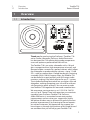
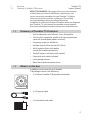
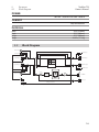
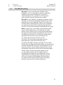
Temblor T10
™
Active Studio Subwoofer
Owner’s Manual
®
www.presonus.com
English
Table of Contents
1Overview — 1
1.1
Introduction — 1
1.2
Summary of Temblor T10
Features — 2
1.3
What is in the box — 2
2.2
Rear-Panel Connections
and Controls — 3
2.1.1Inputs — 3
2.1.2Outputs — 4
2.1.3Power — 4
2.1.4
User Controls — 5
2.2.1
Basic Setup — 7
2.2.2
Advanced Setup — 8
3Tutorials — 10
3.1Subwoofer
Placement — 10
2Hookup — 3
2.1
Hookup Diagrams — 7
3.2
Level Calibration — 11
4Resources — 15
4.1
Technical Specifications — 15
4.2
Block Diagram — 16
4.3
Troubleshooting — 17
4.4
PreSonus Limited Warranty — 18
Temblor T10
Owner’s Manual
1Overview
1.1Introduction
1Overview
1.1
Introduction
0
GND
Thank you for purchasing the PreSonus® Temblor™ T10
active studio subwoofer. PreSonus Audio Electronics
has designed the T10 utilizing high-grade components
to ensure optimum performance that will last.
The Temblor T10 is an active subwoofer with a 10-inch
glass-composite driver, high-temperature voice coil, and
damped rubber surround in a ported cabinet, which allows
the subwoofer to produce higher volume—up to 113 dB
SPL—with less power than a sealed-box design. Featuring
a variable (50 to 130 Hz) lowpass filter, the Temblor T10
can be dialed in to pair perfectly with full-range studio
monitors, making it the ideal solution for any 2.1 system.
The included latching footswitch lets you bypass the sub
altogether, making comparing your mix with or without
sub frequencies quick and easy. You can even cascade
two Temblor T10s together for more and smoother bass.
We encourage you to contact us at 1-225-216-7887 (9
a.m. to 5 p.m. Central Time) with questions or comments
regarding your PreSonus Temblor T10. PreSonus
Audio Electronics is committed to constant product
improvement, and we value your suggestions highly.
We believe the best way to achieve our goal of constant
product improvement is by listening to the real experts:
our valued customers. We appreciate the support you
have shown us through the purchase of this product and
are confident that you will enjoy your Temblor T10!
1
1Overview
1.2
Summary of Temblor T10 Features
Temblor T10
Owner’s Manual
ABOUT THIS MANUAL: We suggest that you use this manual
to familiarize yourself with the features, applications, and
correct connection procedures for your Temblor T10 before
connecting it to the rest of your studio gear. This will help
you avoid problems during installation and setup.
In addition to all the basic info you’ll need to connect and operate
your Temblor T10, this manual also provides several tutorials
that cover subwoofer placement, connections, and calibration.
1.2
Summary of Temblor T10 Features
•• Active subwoofer with 250 watt, Class AB amplifier
•• 10-inch glass-composite woofer with high-temperature
voice coil and damped rubber surround
•• Frequency response: 20-200 Hz
•• Variable lowpass filter control: 50-130 Hz
•• 80 Hz highpass filter (with defeat
switch) for satellite connections
•• Sub/HPF bypass with footswitch control
•• Footswitch with cable included
•• Front-ported cabinet
•• Metal-mesh grille to protect driver
1.3
What is in the box
In addition to this manual, your Temblor
T10 package contains the following:
•• (1) PreSonus Temblor T10 powered subwoofer
•• (1) IEC power cable
•• (1) Footswitch with cable
2
Temblor T10
Owner’s Manual
2Hookup
2.1
Rear-Panel Connections and Controls
2Hookup
2.1
Rear-Panel Connections and Controls
2.1.1 Inputs
Line-level Inputs: The Temblor T10 provides a choice of
three input pairs: two sets of balanced inputs (XLR and
¼” TRS) and one pair of RCA unbalanced inputs. When
both of the balanced connections are in use, the TRS
inputs will take precedence over the XLR inputs. The
RCA inputs will sum into either balanced connection.
Power User Tip: Connect both the left and right inputs if
you are using the onboard crossover in your Temblor T10 to
connect your full-range monitors or if you’re running your
Temblor T10 independently from a stereo source (such as
the Monitor Station or Central Station). This will ensure that
your Temblor T10 receives the low-frequency content from
both channels. If your audio source provides a mono or LFE
output, you only need to connect one input—either L or R.
[+]
2
3
1
Ground
[-]
XLR
TRS
Sleeve:
Ground
Ring: Tip:
[-] [+]
Power User Tip: Connect both the left and right inputs if
you are using the onboard crossover in your Temblor T10 to
connect your full-range monitors or if you’re running your
Temblor T10 independently from a stereo source (such as
the Monitor Station or Central Station). This will ensure that
your Temblor T10 receives the low-frequency content from
both channels. If your audio source provides a mono or LFE
output, you only need to connect one input—either L or R.
Input Gain: Sets the level of the input signal before it is
amplified.
3
2Hookup
2.1
Rear-Panel Connections and Controls
Temblor T10
Owner’s Manual
2.1.2 Outputs
Outputs: The Temblor T10 provides two pairs
of balanced outputs: XLR and ¼” TRS. The fullrange signal connected to the stereo inputs
on the T10 is passed through to these outputs.
Use these outputs to connect your main left
and right studio monitors. If the High Pass Filter
switch is engaged, frequencies below 80 Hz are
not sent from these outputs.
Sub Out: This balanced XLR output sends the low-frequency
signal from the lowpass filter to a second Temblor T10. When
connecting a second T10 to this output, set its Low Pass Filter
control to its highest setting.
2.1.3 Power
IEC Power Connection: Your Temblor T10 accepts a standard
IEC power cord.
Warning: Do not remove the center grounding prong or use a
separate ground-lift adapter, as this could result in electric shock.
Power Switch: This is the On/Off switch. The power status is
indicated by the illuminated logo on the front of the cabinet.
AC Select Switch: The input-power voltage is set at the factory
to correspond with the country to which it was shipped. Use
this switch only if you are using your Temblor T10 in a country
that uses a different standard voltage than is used in the
country where you purchased your T10.
4
2Hookup
2.1
Rear-Panel Connections and Controls
Temblor T10
Owner’s Manual
2.1.4 User Controls
Sub Bypass: Connect the bypass footswitch cable to this ¼”
input. Stepping on the footswitch will bypass the
subwoofer, highpass filter, and Sub Out altogether. This will
allow the signal from your audio source to pass directly
through your Temblor T10 to your full-range studio
monitors and allow you to compare your mix without
subharmonic frequencies. While bypass is active, the LED on
the front of your T10 will flash between red and blue. The
footswitch is latching, so the bypass remains in effect until
you step on it again.
Power User Tip: The T10’s Sub Bypass function is a convenient
way to make sure your mix will sound good on systems with
and without a subwoofer. Bypassing the subwoofer will
let you hear how the mix sounds without it. After all, many
listeners will be using two speakers without a sub, and you
want your mix to sound just as good in a stereo system!
Polarity: The Polarity button reverses the polarity of the
summed input signal.
0
High Pass Filter: Removes frequency content below 80 Hz
from the full-range signal sent from the T10 outputs. This is
useful if your main studio monitors do not have their own
highpass filter. The highpass filter is also bypassed when the
Sub Bypass is enabled.
Power User Tip: Leaving frequency content below 80 Hz
in full-range studio monitors can introduce destructive
cancellations with the highest frequencies that are
reproduced by the Temblor T10. Conversely, this can
reinforce these frequencies and make your mix seem to
have more bass in it than it actually does. By rolling off your
full-range speakers, you will create a more linear frequency
response between the subwoofer and full-range content.
5
2Hookup
2.1
Rear-Panel Connections and Controls
Temblor T10
Owner’s Manual
Low Pass Filter: This control determines the upper end of the
frequency range reproduced by the Temblor T10. If you have
enabled the onboard highpass filter, set the Low Pass Filter
control to the same value. Otherwise, set the Low Pass Filter
control to the lowest frequency that your main studio monitors
can reliably reproduce. Note that this control only affects the
signal going to the internal amplifier and the Sub Out output
and does not affect the main outputs. If you daisy-chain two
T10s, set the second one’s lowpass filter to its highest setting,
130 Hz, to make sure it reproduces everything it gets
from the first T10.
GND
Ground Lift Switch: In the “Lift” position, this switch adds 1 kΩ
resistance to the ground for the balanced inputs. The Ground
Lift switch doesn’t affect the AC mains safety ground for the
power supply.
Power User Tip: Enabling the ground lift can help to reduce
ground loop noise in your audio system. Ground loops can be
caused by running audio cables with power cables, by older
buildings with improper wiring, or by equipment that generates a
lot of RFI, such as computers, laptop power supplies, and the like.
6
Temblor T10
Owner’s Manual
2Hookup
2.2
Hookup Diagrams
2.2
Hookup Diagrams
2.2.1 Basic Setup
100 - 240 VAC 50-60Hz
On
StudioLive 16.0.2
0
GND
Temblor T10
Sceptre S6 (Right)
Sceptre S6 (Left)
7
Temblor T10
Owner’s Manual
2Hookup
2.2
Hookup Diagrams
2.2.2 Advanced Setup
AudioBox 1818VSL
0
GND
Footswitch
Temblor T10 (Master)
Eris E8 (Right)
Eris E8 (Left)
8
Temblor T10
Owner’s Manual
2Hookup
2.2
Hookup Diagrams
0
GND
Temblor T10 (Slave)
9
3Tutorials
2.2
Hookup Diagrams
Temblor T10
Owner’s Manual
3Tutorials
3.1
Subwoofer Placement
The goal of proper subwoofer placement is to set up your
system so that your subwoofer acts as a natural extension
of your full-range monitors without boosting the overall
bass response of your room or exaggerating any one
frequency or frequency range. Because low frequencies
are not directional—that is, humans cannot perceive the
direction from which low frequencies are coming— you
aren’t limited to placing it facing the mix position.
A quick way to find the best location for your subwoofer is
to temporarily place it in the mix position and play some
program material that contains a lot of bass. Move around
the half of the room where your full-range monitors are
positioned until you find the spot where the bass sounds its
best. Again, it’s important to remember that low frequencies
are not directional, so placing the subwoofer beside or
behind you will not be an issue. In general, you will want
to avoid placing your subwoofer too near to reflective
surfaces, like a wall or in a corner as this will exaggerate
the bass energy and make your T10 sound “boomy.”
Once you find the place in the room where the bass sounds
the smoothest, place your T10 in that spot, return to the
mix position and listen to it again. You may need to adjust
the location; just keep making small adjustment (a foot
or so at a time) until the bass response sounds as even as
possible. Don’t locate your T10 where it will exaggerate
frequencies, as this will have the opposite effect on your
mix. For example, if your system has a bump around 100 Hz,
what you hear will not accurately reflect what is in your
mixes, resulting in less kick-drum punch than you wanted.
10
Temblor T10
Owner’s Manual
3Tutorials
2.2
Hookup Diagrams
3.2
Level Calibration
Matching the levels of the all studio monitors in your
system is an easy extra step that will help you to achieve an
optimal listening environment. You will need an SPL meter
to do this; luckily, there are many inexpensive and free
SPL meter apps for just about every type of smartphone
that will do the job nicely. Below is a brief tutorial on
how to level match your monitors. Note: Make sure that
any effects processors (such as EQs, compressors, and
reverbs) have been bypassed. You’ll want a clean signal.
1.
Connect your studio monitors and
Temblor T10 as shown in the hookup diagram
in Section 2.2.1.
2.
Turn your Temblor T10 and your full-range
studio monitors’ input levels to their lowest
setting.
3.
Play pink noise through your
primary audio source’s outputs. You
should not hear anything yet.
0
GND
11
Temblor T10
Owner’s Manual
3Tutorials
2.2
Hookup Diagrams
Power User Tip: Some DAW applications, including
PreSonus Studio One®, offer a tone generator for this
purpose. If you’re mixing in a DAW application, use
the built-in tone generator or load a sample audio
file or plug-in. After all, your DAW is the beginning
of your mixing environment’s signal path!
4.
Pan the pink noise so it only plays in the left
speaker (hard left).
5.
Begin turning up the outputs of your primary
audio source to their unity-gain setting. “Unity
gain” is the level or setting at which the signal level
is neither boosted nor attenuated, and it is usually
marked by a “U” on the audio device’s level fader or
knob. In many digital interfaces and other digital
devices, the device’s maximum level is also its
unity-gain setting. Please consult your audio
device’s user manual or the manufacturer’s Web
site for more information on its levels and
adjustments.
6.
SPL:
85 dB
Begin slowly increasing the
input sensitivity (volume) of
your left studio monitor until
the acoustic level of the pink
noise reaches 85 dB SPL on your
SPL meter when measured at
your mix position.
12
Temblor T10
Owner’s Manual
3Tutorials
2.2
Hookup Diagrams
7.
Pan the pink noise so that it only plays in the
right speaker (hard right), and repeat step 6 for
the right channel.
8.
Turn your full-range monitors off.
9.
0
GND
SPL:
79 dB
Begin slowly increasing the input
volume on your Temblor T10 until
the acoustic level of the pink
noise reaches 79 dB SPL on your
SPL meter when measured at
mix position.
10. Set the lowpass filter on your T10 to 130 Hz. This
will create an overlap between your T10s and
your full-range system’s frequency responses.
Polarity
GND
13
3Tutorials
2.2
Hookup Diagrams
Temblor T10
Owner’s Manual
11. Play pink noise through your full system and
experiment with the polarity switch on your
Temblor T10 to see which position provides the
best bass response at your mix position. Leave
the polarity switch in the position that provided
the loudest bass response. This means that you
subwoofer is in phase with your full-range system.
12. If you are using the 80 Hz highpass filter on
the T10 to bandpass your full-range monitors,
set the lowpass filter to 80 Hz. If you are using
an external highpass filter for your full-range
monitors, set the lowpass filter to the appropriate
frequency (e.g., if your highpass filter is set
to 100 Hz, set the lowpass filter to the same
frequency). You may need to experiment with
the Low Pass Filter setting on your subwoofer
until you find the smoothest crossover position.
Once the Input Gain control is set on your full-range monitors
and T10, leave it alone; don’t use it as a volume control.
Leave that job to your audio device’s output-level control.
14
Temblor T10
Owner’s Manual
4Resources
4.1
Technical Specifications
4Resources
4.1
Technical Specifications
INPUTS
2- Balanced XLR
2- Balanced ¼” TRS
2- Unbalanced RCA
OUTPUTS
2- Balanced XLR (full range with 80 Hz HPF option)
2- Balanced ¼” TRS (full range with 80 Hz HPF option)
1- Balanced XLR (Sub Out)
PERFORMANCE
Frequency Response
Low Pass Filter Frequency
Signal-to-Noise Ratio
THD
Amplifier Power
Power Consumption
Amplifier Type
Peak SPL at 1m
Woofer
20 Hz – 200 Hz
50 – 130 Hz (variable)
>98 dB
0.019% @ power <160W
170W RMS / 250W Peak
230W
Class AB
113 dB
10” glass-composite
USER CONTROLS
Input Gain Control
Polarity Switch
Low Pass Filter Control
Ground Lift Switch
High Pass Filter Switch
Bypass Footswitch
-30 to +6 dB
0° or 180°
50 Hz to 130 Hz
On/Off
On/Off
On/Off
PROTECTION
RF interference
Output-current limiting
Over-temperature
Turn-on/off transient
Subsonic filter
External mains fuse
15
Temblor T10
Owner’s Manual
4Resources
4.2
Block Diagram
POWER
100-120V ~50/60 Hz or 220-240V ~50/60 Hz
CABINET
Vinyl-laminated MDF
PHYSICAL
Width
Depth
Height
Weight
12.60” (320 mm)
15.75” (400 mm)
15.75” (400 mm)
39.46 lbs (17.9 kg)
Block Diagram
4.2
Left RCA Input
Left TRS Output
Left TRS Input
+
-
-
+
+
Left XLR Input
-
Left XLR Output
80 Hz
+
-
-
-
+
High Pass Filter
+
Right XLR Input
Right XLR Output
Right TRS Output
Low Pass Filter
Right TRS Input
Volume
Right RCA Input
∑
Ground Lift
Limiter
AMP
10” LF DRIVER
50 Hz to 130 Hz
1k
Sub Output
+
Sub Bypass Footswitch
16
4Resources
4.3Troubleshooting
4.3
Temblor T10
Owner’s Manual
Troubleshooting
No power. First ensure that your Temblor T10 is
plugged in. If it’s connected to a power conditioner,
verify that the power conditioner is turned on
and functioning. If it is, yet there is still no power
to the monitor, contact PreSonus for a repair.
No audio. If your Temblor T10 appears to power on but
you hear no sound when playing audio from the mixer
(the lights are on but nobody’s home), first make sure
that the cables connecting the mixer to the subwoofer
are working correctly. Also, verify that the Input Gain
control is set to provide enough amplitude for the signal.
Hum. Usually, hum is caused by a ground loop. Verify
that all audio equipment is connected to the same
power source. If you are not using a power conditioner,
we highly recommend that you add one. Not only will
this help to minimize hum, it will better protect your
equipment from power surges, brownouts, etc.
Try setting the Ground Lift switch to “Lift.”
This adds 1 kΩ resistance to the ground of the
balanced inputs and often eliminates hum.
Use balanced cables whenever possible. If your audio
device does not offer a balanced output, you can connect
it to the unbalanced RCA inputs on the Temblor T10, or
you can connect it to a DI (direct-injection) box, which
will provide a ground-lift switch and a balanced output.
Finally, make sure that your audio cables are not
run near power cables, and use cables that are
the appropriate length for your application. Using
cables that are too long not only increases the risk
of noise, it increases the likelihood that the cables
are coiled, which will essentially create an antenna
that picks up all kinds of audio interference.
17
4Resources
4.4
PreSonus Limited Warranty
4.4
Temblor T10
Owner’s Manual
PreSonus Limited Warranty
PreSonus Audio Electronics, Inc., warrants this product to be
free of defects in material and workmanship for a period of one
year from the date of original retail purchase. This warranty
is enforceable only by the original retail purchaser. To be
protected by this warranty, the purchaser must complete and
return the enclosed warranty card within 14 days of purchase.
During the warranty period PreSonus shall, at its sole and
absolute option, repair or replace, free of charge, any product
that proves to be defective on inspection by PreSonus or its
authorized service representative. If you are located in the USA
and need warranty repair, please submit an online technical
support request at http://support.presonus.com to receive a
return-authorization number and shipping information. If you
are located outside of the USA, please contact the PreSonus
distributor for your region for warranty repairs. All inquiries
must be accompanied by a description of the problem. All
authorized returns must be sent to the PreSonus repair facility
postage prepaid, insured, and properly packaged. PreSonus
reserves the right to update any unit returned for repair.
PreSonus reserves the right to change or improve the design
of the product at any time without prior notice. This warranty
does not cover claims for damage due to abuse, neglect,
alteration, or attempted repair by unauthorized personnel and
is limited to failures arising during normal use that are due to
defects in material or workmanship in the product. Any implied
warranties, including implied warranties of merchantability
and fitness for a particular purpose, are limited in duration to
the length of this limited warranty. Some states do not allow
limitations on how long an implied warranty lasts, so the above
limitation may not apply to you. In no event will PreSonus be
liable for incidental, consequential, or other damages resulting
from the breach of any express or implied warranty, including,
among other things, damage to property, damage based on
inconvenience or on loss of use of the product, and, to the
extent permitted by law, damages for personal injury. Some
states do not allow the exclusion of limitation of incidental or
consequential damages, so the above limitation or exclusion
may not apply to you. This warranty gives you specific legal
rights, and you may also have other rights, which vary from
state to state. This warranty only applies to products sold and
used in the United States of America. For warranty information
in all other countries, please refer to your local distributor.
PreSonus Audio Electronics, Inc.
18011 Grand Bay Ct.
Baton Rouge, Louisiana 70809 USA
1-225-216-7887
www.presonus.com
18
4Resources
4.4
PreSonus Limited Warranty
Temblor T10
Owner’s Manual
19
Dinner is Served
Added bonus: PreSonus’ previously Top Secret recipe for…
Rice Dressing
Ingredients:
••
••
••
••
••
••
••
••
••
••
••
••
1lb ground beef
1 lb chopped chicken liver
1 onion (diced)
2 green peppers (diced)
4-6 celery stalks (diced)
2 garlic cloves (minced)
¼ C. chopped fresh parsley
3 C. chicken stock
6 C. cooked rice
1 Tbs. oil
Salt and pepper to taste
Cayenne pepper to taste
Cooking Instructions:
1. In a large pot, heat oil on medium high and add meat, salt, and pepper to taste.
Stir until meat begins to brown.
2. Lower heat and add all vegetables. Cook until onions are transparent and celery
is very tender. Add stock as necessary to prevent burning.
3. Stir in cooked rice. Add remaining stock and simmer on low until ready to serve.
© 2014 PreSonus Audio Electronics, Inc. All Rights Reserved. Active Integration, AudioBox, DigiMax, FireStudio, Nimbit,
Notion, PreSonus, QMix-AI, StudioLive, Temblor, and XMAX are trademarks or registered trademarks of PreSonus Audio
Electronics, Inc. Capture, Impact, Mixverb, Presence, RedLightDist, SampleOne, Studio One, and Tricomp are trademarks or
registered trademarks of PreSonus Software Ltd. Mac and Mac OS are registered trademarks of Apple, Inc., in the U.S. and
other countries. Windows is a registered trademark of Microsoft, Inc., in the U.S. and other countries. Other product names
mentioned herein may be trademarks of their respective companies. All specifications subject to change without notice...
except the recipe, which is a classic.
Temblor T10
Active Studio Subwoofer
Owner’s Manual
0
GND
18011 Grand Bay Ct. • Baton Rouge,
® Louisiana 70809 USA• 1-225-216-7887
www.presonus.com
Part# 820-GEB0028-C