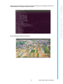
1
User Manual DSPC-8661-PCXE Copyright The documentation and the software included with this product are copyrighted 2012 by Advantech Co., Ltd. All rights are reserved. Advantech Co., Ltd. reserves the right to make improvements in the products described in this manual at any time without notice. No part of this manual may be reproduced, copied, translated or transmitted in any form or by any means without the prior written permission of Advantech Co., Ltd. Information provided in this manual is intended to be accurate and reliable. However, Advantech Co., Ltd. assumes no responsibility for its use, nor for any infringements of the rights of third parties, which may result from its use. Acknowledgements Intel and Pentium are trademarks of Intel Corporation. Microsoft Windows and MS-DOS are registered trademarks of Microsoft Corp. All other product names or trademarks are properties of their respective owners. Product Warranty (2 years) Advantech warrants to you, the original purchaser, that each of its products will be free from defects in materials and workmanship for two years from the date of purchase. This warranty does not apply to any products which have been repaired or altered by persons other than repair personnel authorized by Advantech, or which have been subject to misuse, abuse, accident or improper installation. Advantech assumes no liability under the terms of this warranty as a consequence of such events. Because of Advantech’s high quality-control standards and rigorous testing, most of our customers never need to use our repair service. If an Advantech product is defective, it will be repaired or replaced at no charge during the warranty period. For outof-warranty repairs, you will be billed according to the cost of replacement materials, service time and freight. Please consult your dealer for more details. If you think you have a defective product, follow these steps: 1. Collect all the information about the problem encountered. (For example, CPU speed, Advantech products used, other hardware and software used, etc.) Note anything abnormal and list any onscreen messages you get when the problem occurs. 2. Call your dealer and describe the problem. Please have your manual, product, and any helpful information readily available. 3. If your product is diagnosed as defective, obtain an RMA (return merchandize authorization) number from your dealer. This allows us to process your return more quickly. 4. Carefully pack the defective product, a fully-completed Repair and Replacement Order Card and a photocopy proof of purchase date (such as your sales receipt) in a shippable container. A product returned without proof of the purchase date is not eligible for warranty service. 5. Write the RMA number visibly on the outside of the package and ship it prepaid to your dealer. DSPC-8661-PCXE User Manual Part No. Edition 1 Printed in Taiwan December 2012 ii Declaration of Conformity CE This product has passed the CE test for environmental specifications when shielded cables are used for external wiring. We recommend the use of shielded cables. This kind of cable is available from Advantech. Please contact your local supplier for ordering information. CE This product has passed the CE test for environmental specifications. Test conditions for passing included the equipment being operated within an industrial enclosure. In order to protect the product from being damaged by ESD (Electrostatic Discharge) and EMI leakage, we strongly recommend the use of CE-compliant industrial enclosure products. FCC Class A Note: This equipment has been tested and found to comply with the limits for a Class A digital device, pursuant to part 15 of the FCC Rules. These limits are designed to provide reasonable protection against harmful interference when the equipment is operated in a commercial environment. This equipment generates, uses, and can radiate radio frequency energy and, if not installed and used in accordance with the instruction manual, may cause harmful interference to radio communications. Operation of this equipment in a residential area is likely to cause harmful interference in which case the user will be required to correct the interference at his own expense. FCC Class B Note: This equipment has been tested and found to comply with the limits for a Class B digital device, pursuant to part 15 of the FCC Rules. These limits are designed to provide reasonable protection against harmful interference in a residential installation. This equipment generates, uses and can radiate radio frequency energy and, if not installed and used in accordance with the instructions, may cause harmful interference to radio communications. However, there is no guarantee that interference will not occur in a particular installation. If this equipment does cause harmful interference to radio or television reception, which can be determined by turning the equipment off and on, the user is encouraged to try to correct the interference by one or more of the following measures: Reorient or relocate the receiving antenna. Increase the separation between the equipment and receiver. Connect the equipment into an outlet on a circuit different from that to which the receiver is connected. Consult the dealer or an experienced radio/TV technician for help. FM This equipment has passed the FM certification. According to the National Fire Protection Association, work sites are classified into different classes, divisions and groups, based on hazard considerations. This equipment is compliant with the specifications of Class I, Division 2, Groups A, B, C and D indoor hazards. iii DSPC-8661-PCXE User Manual Technical Support and Assistance 1. 2. Visit the Advantech web site at www.advantech.com/support where you can find the latest information about the product. Contact your distributor, sales representative, or Advantech's customer service center for technical support if you need additional assistance. Please have the following information ready before you call: – Product name and serial number – Description of your peripheral attachments – Description of your software (operating system, version, application software, etc.) – A complete description of the problem – The exact wording of any error messages Safety Instructions 1. 2. 3. 4. 5. 6. 7. 8. 9. 10. 11. 12. 13. 14. 15. 16. 17. 18. 19. 20. 21. Read these safety instructions carefully. Keep this User Manual for later reference. Disconnect this equipment from any AC outlet before cleaning. Use a damp cloth. Do not use liquid or spray detergents for cleaning. For plug-in equipment, the power outlet socket must be located near the equipment and must be easily accessible. Keep this equipment away from humidity. Put this equipment on a reliable surface during installation. Dropping it or letting it fall may cause damage. The openings on the enclosure are for air convection. Protect the equipment from overheating. DO NOT COVER THE OPENINGS. Make sure the voltage of the power source is correct before connecting the equipment to the power outlet. Position the power cord so that people cannot step on it. Do not place anything over the power cord. All cautions and warnings on the equipment should be noted. If the equipment is not used for a long time, disconnect it from the power source to avoid damage by transient overvoltage. Never pour any liquid into an opening. This may cause fire or electrical shock. Never open the equipment. For safety reasons, the equipment should be opened only by qualified service personnel. If one of the following situations arises, get the equipment checked by service personnel: The power cord or plug is damaged. Liquid has penetrated into the equipment. The equipment has been exposed to moisture. The equipment does not work well, or you cannot get it to work according to the user's manual. The equipment has been dropped and damaged. The equipment has obvious signs of breakage. DO NOT LEAVE THIS EQUIPMENT IN AN ENVIRONMENT WHERE THE STORAGE TEMPERATURE MAY GO BELOW -20° C (-4° F) OR ABOVE 60° C (140° F). THIS COULD DAMAGE THE EQUIPMENT. THE EQUIPMENT SHOULD BE IN A CONTROLLED ENVIRONMENT. DSPC-8661-PCXE User Manual iv 22. CAUTION: DANGER OF EXPLOSION IF BATTERY IS INCORRECTLY REPLACED. REPLACE ONLY WITH THE SAME OR EQUIVALENT TYPE RECOMMENDED BY THE MANUFACTURER, DISCARD USED BATTERIES ACCORDING TO THE MANUFACTURER'S INSTRUCTIONS. 23. The sound pressure level at the operator's position according to IEC 704-1:1982 is no more than 70 dB (A). DISCLAIMER: This set of instructions is given according to IEC 704-1. Advantech disclaims all responsibility for the accuracy of any statements contained herein. Safety Precaution - Static Electricity Follow these simple precautions to protect yourself from harm and the products from damage. To avoid electrical shock, always disconnect the power from your PC chassis before you work on it. Don't touch any components on the CPU card or other cards while the PC is on. Disconnect power before making any configuration changes. The sudden rush of power as you connect a jumper or install a card may damage sensitive electronic components. v DSPC-8661-PCXE User Manual DSPC-8661-PCXE User Manual vi Contents Chapter 1 Introduction..........................................1 1.1 1.2 1.3 1.4 1.5 Introduction ............................................................................................... 2 Features .................................................................................................... 2 Package Content....................................................................................... 2 Product Specifications............................................................................... 2 Block Diagram........................................................................................... 4 Figure 1.1 Block Diagram ............................................................ 4 Typical Application .................................................................................... 4 Figure 1.2 Typical Application...................................................... 4 HW Introduction ........................................................................................ 5 1.7.1 Dimension ..................................................................................... 5 Figure 1.3 Top View of DSPC-8661-PCXE ................................. 5 Figure 1.4 Bottom View of DSPC-8661-PCXE ............................ 6 Figure 1.5 Side View of DSPC-8661-PCXE ................................ 6 1.7.2 Input / Output Ports....................................................................... 7 Optional Accessories .............................................................................. 14 1.8.1 JTAG Debug Board (optional)..................................................... 14 1.8.2 Audio and Loop-out Board (optional) .......................................... 14 1.8.3 DIO and Control Board (optional) ............................................... 15 1.6 1.7 1.8 Chapter Chapter Chapter 2 Linux Demo Program ........................17 2.1 2.2 Introduction ............................................................................................. 18 Running PD Demo .................................................................................. 18 2.2.1 DSPCI-8661 Hardware settings.................................................. 18 2.2.2 Boot From Customized Ubuntu disc ........................................... 19 2.2.3 PCIe card status check ............................................................... 19 2.2.4 Run Demonstration ..................................................................... 20 3 Windows Driver Installation .............23 3.1 3.2 3.3 For Windows XP ..................................................................................... 24 For Windows Vista .................................................................................. 27 For Windows 7 ........................................................................................ 31 4 Firmware Loader for Windows .........37 vii DSPC-8661-PCXE User Manual DSPC-8661-PCXE User Manual viii Chapter 1 Introduction 1 1.1 Introduction Design with TI TMS320DM8168 SoC, DSPC-8661-PCXE is a full-functional video processing platform with 16-ch composite video and audio inputs based on standard half-length PCIe board form factor. The board supports H.264 / MJPEG / RAW encode / decode up to D1 resolution at real-time frame rate (30/25fps) for all channels simultaneously. The HDMI provides up to 1080p 60fps video / audio outputs that fulfills the high-definition display requirements. Equipped with a high-performance C674X Digital Signal Processor (DSP), DSPC-8661-PCXE can afford a system's host processing by executing image enhancement and video analytics programs. The I2C and UART interfaces are designed for extending the control and indicator functions like RS-485 and DIO (on the optional DIO & Control Board). Furthermore, the versatile peripherals of Giga LAN, SATA and USB ports enriches the data communication, storage as well as user interface functions while the device works at standalone mode. With an easy-to-use software development kit (SDK), the DSPC8661-PCXE is an ideal solution for system integrators to implement diverse videoprocessing related applications that fits a broad spectrum of customer requirements. 1.2 Features Powered by TI TMS320DM8168 SoC 16-ch composite video and audio inputs H.264 / MJPEG H/W encoding up to 480fps at D1 H.264 / MJPEG H/W decoding up to 480fps at D1 One HDMI supports AV display up to 1080p at 60fps Embedded with 1.0GHz C674X VLIW DSP Versatile peripherals: Giga LAN port, SATA, USB 2.0, I 2 C and UART Dual working modes: PCIe device mode and standalone mode Half-size form factor and fanless H/W design Windows / Linux PC driver and SDK with sample codes 1.3 Package Content DSPC-8661-PCXE board x1 16xBNC + 8xRCA to DVI octopus cable x1 1.4 Product Specifications Video Input Channels 16 Input Format Composite for NTSC / PAL Resolution Up to D1(720x576) Compression H.264 / MJPEG / RAW Max. Frame Rate 480/400fps (NTSC/PAL) at D1 Bit Rate Control CBR & VBR Connector DVI x1 (for connecting 16x BNC + 8xRCA octopus cable). Pin Header x1 (alternative for 16-ch video + 8-ch audio inputs) DSPC-8661-PCXE User Manual 2 Channels 8 + 8 (optional) Format Raw Sampling Rate Up to 16bit, 44KHz Connector DVI x1 (8-ch audio shared with video input connector) Pin Header x1 (for connecting the optional Audio & Loop-out Board; supports the other 8ch audio-in) RCA 1 Loop-out 16-ch Pin Header on board (connecting to the optional Audio & Loop-out Board) HDMI out 1, resolution up to 1080p, frame rate up to 60 fps Peripherals Giga Lan Port RJ45 x1 USB 2.0 Port A-type Female x1 SATA Port x1 (3.0 Gbps) I2C and UART Pin-header x1 for connecting the optional DIO and Control Board Data Bus PCIe Express 2.0, Gen2, x1 Accessories Cable 16xBNC + 8xRCA to DVI Octopus Cable Expansion Board (optional) JTAG Debug Board Audio & Loop-out Board DIO & Control Board Physical Characteristics Power Consumption < 26 W Operating Temperature -20 ~ 70° C / -4 ~158° F (with air flow) Dimensions 140 x 111.15mm / 5.51” x 4.38” Software Supported OS by driver Windows XP / XPe / Vista / 7, Linux SDK User’s Manual, Programming Guide, Sample Codes Demo Program 16-ch Video Capturing and H.264 Encoding at PCIe Device Mode Applications PCIe Device Mode PCIe digital video capturing & encoding card PCIe video decoder card with HDMI out PCIe DSP-based intelligent video analytic card Standalone Mode Embedded IP video encoder / video recorder Embedded IP video decoder with HDMI out Embedded IP intelligent video analytic box 3 DSPC-8661-PCXE User Manual Introduction Video Output Chapter 1 Audio Input 1.5 Block Diagram Video Loop & Audio I/O UART1 UART0 Debug HDMI Output BT.656 TI TVP5158 Analog Video Output I2S BT.656 TI TMS320DM8168 BT.656 I2S SATA PCIe Gen 2 x1 BT.656 TI TVP5158 x16 1Gb DDR3 MICREL KSZ9021GN USB I2S TI TVP5158 RCA RJ45 GMII TI TVP5158 HDMI PC Host I2S x16 1Gb DDR3 32KB I2C EEPROM x16 1Gb DDR3 x16 1Gb DDR3 32Mb SPI Flash Figure 1.1 Block Diagram 1.6 Typical Application Network PCIe Device Mode Decode Image Processing Video AnalyƟcs Display + Analog Camera x16 Encode DSPC-8661-PCXE Standalone Mode X86 PC -Windows OS - Linux OS Storage Network Image Processing Video AnalyƟcs Decode Display Analog Camera x16 DSPC-8661-PCXE - Linux OS Encode Figure 1.2 Typical Application DSPC-8661-PCXE User Manual 4 Storage Chapter 1 1.7 HW Introduction 1.7.1 Dimension Introduction Figure 1.3 Top View of DSPC-8661-PCXE 5 DSPC-8661-PCXE User Manual Figure 1.4 Bottom View of DSPC-8661-PCXE Figure 1.5 Side View of DSPC-8661-PCXE DSPC-8661-PCXE User Manual 6 Boot Mode Switch Audio & Loop-out Port (Audio-in ch9~16) DIO & Control Port JTAG Debug Port Chapter 1 1.7.2 Input / Output Ports Giga LAN Port SATA II Port RCA USB Port DVI Port (16x Video-in) (Audio-in ch1~ch8) (AlternaƟve) AV inputs Port PCIe (16x Video-in) Gen2 x1 (Audio-in ch1~ch8) 1.7.2.1 Boot Mode Switch DSPC-8661-PCXE supports dual working modes: PCIe device mode and Standalone mode. The Boot Mode Switch is for switching the two boot modes. PCIe boot (PCIe device mode): 1:OFF , 2:ON, 3:OFF , 4:ON (default) NAND Flash boot (Standalone Mode): 1:ON , 2:OFF, 3:ON , 4:OFF (A boot code for 3rd party program development in the NAND Flash is needed) 7 DSPC-8661-PCXE User Manual Introduction HDMI 1.7.2.2 DVI Port The DVI port connects with the octopus cable for providing 16ch Video + 8ch Audio inputs (ch1~ch8). Pin number Pin signal Pin number Pin signal 1 VIDEO_IN1 13 VIDEO_IN13 2 VIDEO_IN2 14 VIDEO_IN14 3 VIDEO_IN3 15 VIDEO_IN15 4 VIDEO_IN4 16 VIDEO_IN16 5 VIDEO_IN5 17 AUDIO_IN1 6 VIDEO_IN6 18 AUDIO_IN2 7 VIDEO_IN7 19 AUDIO_IN3 8 VIDEO_IN8 20 AUDIO_IN4 9 VIDEO_IN9 21 AUDIO_IN5 10 VIDEO_IN10 22 AUDIO_IN6 11 VIDEO_IN11 23 AUDIO_IN7 12 VIDEO_IN12 24 AUDIO_IN8 DSPC-8661-PCXE User Manual 8 Pin signal Pin number Pin signal 1 TMS 2 TRSTn 3 TDI 4 GND 5 VCC_3V3 6 7 TDO 8 9 RTCK 10 GND 11 TCK 12 GND 13 EMU0 14 EMU1 15 EMU_RSTn 16 GND GND 17 EMU2 18 EMU3 19 EMU4 20 GND 21 NA 22 NA 23 UART_RXD 24 UART_TXD 26 VCC_3V3 25 1.7.2.4 DIO & Control Port The DIO & control port connects with the DIO & control board (optional) through I2C and UART for providing: 16x DI + 8x DO RS485 Pin number Pin signal Pin number Pin signal 1 UART1_TXD 2 VCC_5V 3 UART1_RXD 4 VCC_5V 5 RS485_DIR 6 GND 7 IIC1_SCL 8 VCC_3V3 9 IIC1_SDA 10 9555_INTn 9 DSPC-8661-PCXE User Manual Introduction Pin number Chapter 1 1.7.2.3 JTAG Debug Port The JTAG debug port connects with the JTAG debug board (optional) for software programming and debugging. 1.7.2.5 Audio and Loop-out Port The audio & loop-out port connects with the audio & loop-out board (optional) for providing: Audio line-in, line-out and microphone-in 8-ch audio-in (ch9~ch16) 16-ch video loop-out. Pin number Pin signal Pin number Pin signal 1 VCC_3V3 2 VCC_1V8 3 V_loop_1 4 AUDIO_IN9 5 V_loop_2 6 AUDIO_IN10 7 V_loop_3 8 AUDIO_IN11 9 V_loop_4 10 AUDIO_IN12 11 GND 12 GND 13 V_loop_5 14 AUDIO_IN13 15 V_loop_6 16 AUDIO_IN14 17 V_loop_7 18 AUDIO_IN15 19 V_loop_8 20 AUDIO_IN16 21 GND 22 GND 23 V_loop_9 24 V_loop_13 25 V_loop_10 26 V_loop_14 27 V_loop_11 28 V_loop_15 29 V_loop_12 30 V_loop_16 31 GND 32 GND 33 AU_3101_DIN 34 RSTOUTn 35 AU_3101_DOUT 36 AU_3101_MCLK 37 IIC0_SCL 38 AU_3101_BCLK 39 IIC0_SDA 40 AU_3101_WCLK DSPC-8661-PCXE User Manual 10 Chapter 1 1.7.2.6 AV inputs Port This pin header is an alternative to DVI port for providing 16ch video-in and 8ch audio-in (ch1~ch8) functions. For some application scenarios that the octopus cable is not desired, users can utilize this port for connecting to the BNC connectors and RCA connectors on the brackets directly. Introduction Pin number Pin signal Pin number Pin signal 1 GND 2 GND 3 VIDEO_IN5 4 AUDIO_IN1 5 VIDEO_IN6 6 AUDIO_IN2 7 GND 8 GND 9 VIDEO_IN7 10 AUDIO_IN3 11 VIDEO_IN8 12 AUDIO_IN4 13 GND 14 GND 15 VIDEO_IN9 16 AUDIO_IN5 17 VIDEO_IN10 18 AUDIO_IN6 19 GND 20 GND 21 VIDEO_IN11 22 AUDIO_IN7 23 VIDEO_IN12 24 AUDIO_IN8 25 GND 26 GND 27 VIDEO_IN13 28 GND 29 VIDEO_IN14 30 VIDEO_IN1 31 GND 32 VIDEO_IN2 33 VIDEO_IN15 34 GND 35 VIDEO_IN16 36 VIDEO_IN3 37 GND 38 VIDEO_IN4 39 GND 40 GND 11 DSPC-8661-PCXE User Manual 1.7.2.7 Giga LAN Port The Giga LAN port is a standard RJ45 connector for providing Ethernet function. Pin number Pin signal 1 MDI0_P 2 MDI0_N 3 MDI1_P 4 MDI2_P 5 MDI2_N 6 MDI1_N 7 MDI3_P 8 MDI3_N Left LED Orange Color LED Right LED Green Color LED 1.7.2.8 SATA II Port The SATA II Port is a standard SATA connector for providing data storage functions Pin number Pin signal 1 GND 2 CON.SATA_TXP0 3 CON.SATA_TXN0 4 GND 5 CON.SATA_RXN0 6 CON.SATA_RXP0 7 GND DSPC-8661-PCXE User Manual 12 Pin signal 1 USB0_VBUS_CONN 2 USB0_DN 3 USB0_DP 4 GND Introduction Pin number 1.7.2.10 HDMI This standard HDMI connector is for connecting with monitor / display devices for providing high definition video output functions. Pin number Pin signal Pin number Pin signal 1 HDMI_TMDSDP2 11 GND 2 GND 12 HDMI_TMDSCLKN 3 HDMI_TMDSDN2 13 HDMI0_CEC_C 4 HDMI_TMDSDP1 14 GND 5 GND 15 HDMI0_DCLK_C 6 HDMI_TMDSDN1 16 HDMI0_DSDA_C 7 HDMI_TMDSDP0 17 GND 8 GND 18 HDMI0_CN_5V 9 HDMI_TMDSDN0 19 HDMI0_HPD_C 10 HDMI_TMDSCLKP 1.7.2.11 RCA The RCA connector is for connecting with monitor / display devices for provide standard definition video output functions. 13 Chapter 1 1.7.2.9 USB Port The USB port is a standard type A female USB connector for providing USB OTG functions. DSPC-8661-PCXE User Manual 1.8 Optional Accessories 1.8.1 JTAG Debug Board (optional) The JTAG debug board (P/N: DSPC8661ACY001-E) is an optional accessory of DSPC-8661-PCXE for monitoring the board operating status and FW/SW programming. A board-to-board flat cable is attached. 1.8.2 Audio and Loop-out Board (optional) The Audio and Loop-out Board (P/N: DSPC8661ACY002-E) is an optional accessory of DSPC-8661-PCXE for providing: Audio line-out, Mic-out and Line-in by phone jack Video loop-out ch1 ~ch16 Audio in ch9 ~ ch16 A 16xBNC+8xRCA to DVI cable and a board-to-board flat cable are attached. Line-out Mc-out Lin-in DSPC-8661-PCXE User Manual 14 Pin number Pin signal 1 Video_Loop1 16 Video_Loop16 2 Video_Loop2 17 Audio_9 3 Video_Loop3 18 Audio_10 4 Video_Loop4 19 Audio_11 5 Video_Loop5 20 Audio_12 6 Video_Loop6 21 Audio_13 7 Video_Loop7 22 Audio_14 8 Video_Loop8 23 Audio_15 9 Video_Loop9 24 Audio_16 10 Video_Loop10 11 Video_Loop11 12 Video_Loop12 C1 GND 13 Video_Loop13 C2 GND 14 Video_Loop14 C3 GND 15 Video_Loop15 C4 GND 1.8.3 DIO and Control Board (optional) The DIO and Control Board (P/N: DSPC8661ACY003-E) is an optional accessory of DSPC-8661-PCXE for providing: 16x digital input 8x digital output (relay) RS485 A board-to-board flat cable is attached. Pin 1 Pin 2 Pin 40 15 DSPC-8661-PCXE User Manual Introduction Pin signal Chapter 1 Pin number Pin number Pin signal Pin number Pin signal 1 7 COM 21 2 7 NC 22 GND 3 7 NO 23 +5V 4 8 NC 24 GND 5 8 NO 25 Alarm in 15 6 8 COM 26 Alarm in 16 7 6 COM 27 Alarm in 13 8 6 NO 28 Alarm in 14 9 5 COM 29 Alarm in 11 10 5 NO 30 Alarm in 12 11 4 COM 31 Alarm in 09 12 4 NO 32 Alarm in 10 13 3 COM 33 Alarm in 07 14 3 NO 34 Alarm in 08 15 2 COM 35 Alarm in 05 16 2 NO 36 Alarm in 06 17 1 COM 37 Alarm in 03 18 1 NO 38 Alarm in 04 19 +485 39 Alarm in 01 20 -485 40 Alarm in 02 DSPC-8661-PCXE User Manual 16 Chapter 2 2 Linux Demo Program 2.1 Introduction This chapter describes how to set up the software demonstration for DSPC-8661PCXE (abbreviated as DSPC-8661 below) board. It will show you how to use the hardware and run demo software. The release package includes Ubuntu 10.04.3 LTS Customized ISO image with DSPCI-8661 Linux driver. The guide details the steps to setup the hardware and run the demo. Please follow the steps in sequence to get the demonstration working on your PC platform. McFW on Netra Linux NTSC/PAL Video Decoder HDVPSS VFCC Deinterlace H.264 Encode PCIe Streaming (EP) PC Linux Monitor VGAOut Ubuntu GUI (X-Window) H.264 Decode (mplayer) V4L2 Driver (Frame Buffer) PCIe Streaming (RC) 2.2 Running PD Demo 2.2.1 DSPCI-8661 Hardware settings The required peripherals on PCIE card for software demonstration include: 1. The boot mode switch (TSW1) should be set as PCIE device mode : 0101. 0101 2. 3. 4. 5. Connect to input source you want. Connect with JTAG debug board for UART message and JTAG function (optional). COM port cable (or USB-to-COM cable, optional). Insert DSPC-8661 into your PC PCIE slot and ready for boot, as shown in below. DSPC-8661-PCXE User Manual 18 JTAG debug board 2.2.2 Boot From Customized Ubuntu disc Please download the “DSPC-8661-PCXE Linux SDK + Live Linux Demo” data from Advantech “Support & Download” web page and save in the hard disk. Setting PC to boot from this bootable device with ISO image and chose “Try Ubuntu without installing” in boot menu. Demo will run on this OS. Pre-built DSPC-8661 Linux driver will be loaded after booting into Ubuntu. 2.2.3 PCIe card status check Before running the demonstration, you could use following command in Terminal to check the installation. PCI utility will show the information for DSPC-8661 and the driver in use. $ sudo lspci-v-d :b800 02:00.0 Non-VGA unclassified device: Texas Instruments Device b800 (rev 01) Flags: bus master, fast devsel, latency 0, IRQ 16 Memory at feaff000 (32-bit, non-prefetchable) [size=4K] Memory at fd800000 (32-bit, prefetchable) [size=8M] Memory at fd000000 (32-bit, prefetchable) [size=8M] Memory at <unassigned> (32-bit, prefetchable) Capabilities: [40] Power Management version 3 Capabilities: [50] Message Signalled Interrupts: Mask- 64bit+ Queue=0/0 EnableCapabilities: [70] Express Endpoint, MSI 00 Capabilities: [100] Advanced Error Reporting <?> Kernel driver in use: ti81xx Kernel modules: ti816x_pcie 19 DSPC-8661-PCXE User Manual Linux Demo Program 16-BNC to DVI Octopus Cable Chapter 2 DSPC-8661 2.2.4 Run Demonstration After booting into Ubuntu, double-click auto_boot in desktop and chose “Run in Terminal”, it might take 10 seconds to wait on-board firmware running. Then double-click video.sh in desktop and chose “Run in Terminal” to start demo. User could set the arguments, channel , frame rate and format, after executing video.sh script. Set “all” to capture all channels and ‘0-15’ for individually channel. Frame rate depends on the format of the video source: 25 for PAL, 30 for NTSC. And set encode format: 0= H264; 1=RAW ;2=MJPEG ; 9=previous setting. DSPC-8661-PCXE User Manual 20 Chapter 2 After arguments setting the terminal will show decoding error message until PCIe onboard firmware is running, as shown in below. Linux Demo Program Multiple Mplayer windows will pop-out. 21 DSPC-8661-PCXE User Manual DSPC-8661-PCXE User Manual 22 Chapter 3 Windows Driver Installation For Windows XP For Windows Vista For Windows 7 3 3.1 For Windows XP 1. Device Found: After DSPC-8661 is plugged into your PC, Windows scans the hardware and finds out DSPC-8661. Open your “Device Manager” and it show as the following figure. If it doesn’t show, or you want to reinstall the driver, please re-scan hardware for DSPC-8661. 2. If “Found New Hardware Wizard” shows, click on “Cancel” to prevent it from blocking the driver installer. Make sure the wizard is closed, or the installation process fails. DSPC-8661-PCXE User Manual 24 4. Click “Next” when the installation wizard shows. 25 Windows Driver Installation Double click on “Install.bat” to begin the installation. Chapter 3 3. DSPC-8661-PCXE User Manual 5. Choose “Agree” and click “Next” on EULA step. 6. The driver wizard proceeds to install. DSPC-8661-PCXE User Manual 26 When the installation successfully completed, click “Finish” to end the installation. 1. Device Found: After DSPC-8661 is plugged into your PC, Windows scans the hardware and finds out DSPC-8661. Open your “Device Manager” and it show as the following figure. If it doesn’t show, or you want to reinstall the driver, please re-scan hardware for DSPC-8661. 27 DSPC-8661-PCXE User Manual Windows Driver Installation 3.2 For Windows Vista Chapter 3 7. 2. 3. If “Found New Hardware Wizard” shows, click on “Cancel” to prevent it from blocking the driver installer. Make sure the wizard is closed, or the installation process fails. Double click on “Install.bat” to begin the installation. DSPC-8661-PCXE User Manual 28 5. Choose “Agree” and click “Next” on EULA step. Windows Driver Installation Click “Next” when the installation wizard shows. Chapter 3 4. 29 DSPC-8661-PCXE User Manual 6. The will show windows Security message, click “Install”. The driver wizard proceeds to install. DSPC-8661-PCXE User Manual 30 When the installation successfully completed, click “Finish” to end the installation. 1. Device Found: After DSPC-8661 is plugged into your PC, Windows scans the hardware and finds out DSPC-8661. Open your “Device Manager” and it show as the following figure. If it doesn’t show, or you want to reinstall the driver, please re-scan hardware for DSPC-8661. 31 DSPC-8661-PCXE User Manual Windows Driver Installation 3.3 For Windows 7 Chapter 3 7. 2. Double click on “Install.bat” to begin the installation. 3. Click “Next” when the installation wizard shows. DSPC-8661-PCXE User Manual 32 Choose “Agree” and click “Next” on EULA step. Chapter 3 4. Windows Driver Installation 33 DSPC-8661-PCXE User Manual 5. The will show windows Security message, click “Install”. The driver wizard proceeds to install. DSPC-8661-PCXE User Manual 34 When the installation successfully completed, click “Finish” to end the installation. Chapter 3 6. Windows Driver Installation 35 DSPC-8661-PCXE User Manual DSPC-8661-PCXE User Manual 36 Chapter 4 4 Firmware Loader for Windows “Dspc8661loader” is a specific application, which is designed to load the Linux firmware into the device DSPC-8661 and active it under Windows environment. If there is any need to load different versions of firmware, you can use this tool to achieve it. The application can also load the firmware into the multiple boards. Notice that the firmware can be loaded only one time after rebooting the PC. Note! For developing DSPC-8661 firmware, we suggest the developers to download the Linux EZ Software Development Kit (EZSDK) for DaVinci DM816X Video Processors in the Texas Instruments (TI) website. “Dspc8661loader” looks like as following: Display which board to load. Display the firmware path. The following is the loading flow: DSPC-8661-PCXE User Manual 38 If the driver and the Microsoft application are successfully installed, please refer to the following steps to start to use the application “Dspc8661Loader”. Find the application “Dspc8661Loader” in “DSPC-8661 Loader\application” 2. Run “Dspc8661Loader” as administrator. 39 Firmware Loader for Windows 1. Chapter 4 Before starting to use the “Dspc8661loader”, install the specific driver and the Microsoft application “vcredist_x862008sp1.exe” first. The driver is located in the folder “DSPC-8661 Loader\driver”, and the Microsoft application “vcredist _x862008sp1.exe” is located in the folder “DSPC-8661 Loader\application”. DSPC-8661-PCXE User Manual 3. Find all the firmware to load. A. Find the firmware *.bin to load. B. Find the firmware *.scr to load DSPC-8661-PCXE User Manual 40 Chapter 4 C. Find the firmware *.ker to load. Firmware Loader for Windows D. Find the firmware *.fs to load 4. Start to load all the firmware by pressing the button “Load”. 41 DSPC-8661-PCXE User Manual 5. Wait for about 30 seconds, then message “Load finish” pop up once the loading already finished. DSPC-8661-PCXE User Manual 42 Chapter 4 Firmware Loader for Windows DSPC-8661-PCXE User Manual 43 www.advantech.com Please verify specifications before quoting. This guide is intended for reference purposes only. All product specifications are subject to change without notice. No part of this publication may be reproduced in any form or by any means, electronic, photocopying, recording or otherwise, without prior written permission of the publisher. All brand and product names are trademarks or registered trademarks of their respective companies. © Advantech Co., Ltd. 2012