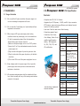
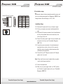
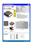
1
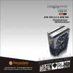
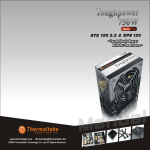
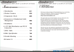
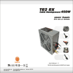
Purepower 500W
>> 11
Purepower 500W
ATX 12V 2.0 version
>> >>
ATX 12V 2.0 version
Note :
Table of contents
1. Introduction --------------------------------------- 01
2. Installation
2.1 Usage Illustration --------------------------- 03
2.2 Installation Steps --------------------------- 04
3. Product Specification
3.1 Output Specification ----------------------- 05
3.2 Purepower 500W Power Supply -----
08
4. Trouble Shooting ------------------------------- 10
Thermaltake Purepower Power Supply
Thermaltake Purepower Power Supply
www.rackmountnet.com
Purepower 500W
>> 01
Purepower 500W
ATX 12V 2.0 version
>> 10
ATX 12V 2.0 version
4. Trouble shooting
1. Introduction
Condition 1: No DC output. The fan or fans are motionless
Check:
1-1 Is the AC inlet plug firmly plugged into the PSU inlet
socket?
1-2 Is the wall socket, extension power cord, power strip
or surge protector in use, fully functional and wall power
switch turned 'ON'?
1-3 Is the Main Board socket (24pin) plug fully and firmly
inserted?
We live up to the promise of Thermaltake logo in
our unending quest for excellence.
Shall you have any suggestion or comments,
please access our web site :
http://www.thermaltake.com
or e-mail to :
[email protected]
we appreciate your kindly feedback and you will
receive the prompt response from our customer
service team.
Thank you for choosing a quality Thermaltake Purepower
500W PC Power Supply. We trust that you will find it
providing you with many years of service.
You can always find a Thermaltake Purepower 500W PC
Power Supply that is suitable for all of your modern PC
power needs.
Please take the time in familiarize yourself with the power
Condition 2: The fan or fans began rotating and then stopped.
The system hangs without proceeding any further.
Check:
2-1 Are the peripheral connectors firmly plugged into
accessory devices, such as the main hard drive, CD ROM
, etc?
2-2 If a plug has been inadvertently connected in an off-set or
reversed position, unplug the AC power source, reconnect
the offending connectors and then wait for 30 seconds
before replug in the AC power source and try again.
Note:
If the power supply still cannot or is still unable to power up after
following the above instruction, please send the unit back to
your dealer or retailer for after sales service.
supply, its connectors and the contents of this manual
before proceeding with the installation of the power unit.
You will need a Phillips crosshead screwdriver, perhaps
your PC case manual and most certainly your
motherboard manual.
Thermaltake Purepower Power Supply
Thermaltake Purepower Power Supply
www.rackmountnet.com
Purepower 500W
>> 09
Purepower 500W
ATX 12V 2.0 version
>> 02
ATX 12V 2.0 version
Technology Features
Should you have any questions regarding the
aforementioned steps, please contact Thermaltake
directly. Failure to follow the proper procedures may
12 cm Fan - High
thermal performance
New 24(20) pin
Main Connector
Dual +12V Rails
cause sever bodily harm or PC component damage.
For Support or General Inquiries, please contact us at:
6 pin PCIExpress Connector
5-pin S-ATA Connector
Mirror Coating
1 Thermaltake Technology USA
Toll Free: (800)988-1088
Cable Application
Email: [email protected]
Intelligent Cable
Management:
>Black cable sleeving
>Optimum air-flow
2 Thermaltake Europe B.V.
Tel:+31-10-409-0150
Email: [email protected]
Total Output Connector
3 Thermaltake Beijing Co.Ltd.
Tel:+86-10-82883159/3189 ext.16
X1
X1
24-pin
Main Connector
X2
X8
4-pin
+12V Power
Connector
4-pin
Peripheral Power
Connector
X4
4-pin
Floppy Drive
Connector
X1
5-pin
S-ATA Connector
Email: [email protected]
6-pin
PCI Express
Connector
4 Thermaltake Australia and New Zealand Pty Ltd
Tel:+613-9763-1622
Max.
Load
+3.3 V
+5 V
+12 V 1
22 A
32 A
14 A
+12 V
2
15 A
-12 V
+5 VSB
0.3 A
2A
Min.
Load
0.5 A
0.5 A
1.0 A
1.0 A
0.0 A
0.0 A
Load
Reg.
+5% ~ -5%
+5% ~ -5%
+5% ~ -5%
+5% ~ -5%
+10% ~ -10%
+5% ~ -5%
50
mV
50
mV
100
mV
100
mV
150
mV
50
mV
Ripple
V(p-p)
Thermaltake Purepower Power Supply
Email: [email protected]
5 Thermaltake Japan Inc.
Email: [email protected]
Thermaltake Purepower Power Supply
www.rackmountnet.com
Purepower 500W
>> 03
Purepower 500W
ATX 12V 2.0 version
2 Installation
3.2 Purepower
2.1 Usage illustration
Features:
2.1.1 Do not pull the AC power cord when the power supply is in
use or else damage to components will result.
>> 08
ATX 12V 2.0 version
500W PSU Specification
-Complies with ATX 12V 2.0 Version.
-Supports 6-pin PCI-Express, 4 S-ATA, and 20+4 pin connector.
-PFC function, improved energy effici ency and reduced current
2.1.2 Do not store the Power Supply in a high humidity and high
temperature environment.
load on AC delivery systems.
-Low noise 12cm fan and mirror effect housing.
-Protections against Input
2.1.3 When using an ATX type power supply under testing
SPECIFICATION
Protection, Over Power,
conditions where the power supply unit is not installed in a
PC with its components, please follow the steps below:
1)Please take a paper clip and untwist it.
Over Voltage, Short-Circuit,
and No Load Operation.
-Safety / EMI Approvals:
2)Make sure the power supply unit is in the "OFF" position.
UL, CUL, TUV, FCC, and
3)Locate the 20 or 24 pin motherboard connector from the
CB certif ication.
power supply unit.
P/N
W0100
Maximum Power
500 Watts
Color
Black
Switches
ATX Logic on- off additional power
rocker switch(115/230 V selector switch)
PFC (Power
Factor
Correction)
N/A
Cooling System
One 12cm Fan:
SPEED : 2400 RPM(+/-10%)
DIMENSION : 120 x 120 x 25 mm
TEMP. AUTO CONTROL
1525 rpm at 28.6C~2393 rpm
at 64.8C
Noise
17dB at 1300 RPM
4)Plug one side of the paper clip into the green wire hole.
5)Plug the other side of the paper clip into any of the black
wire holes.
6)Turn on the PSU to see if the power supply fans turn on.
2.1.4 High voltages exist in the power supply. Do not open the
power supply case unless you are an authorized service
technician or electrician.
P. G. Signal
100-500
ms
Over Voltage
Protection
Recycle AC to
Reset
+5V output 6.25 0.75V
+3.3V output 4.0 0.30V
+12V output 15.0 0.6V
DIMENSIONS
2.1.5 All warrantees and guarantees shall be voided should there
Unit Size
14cm(L)x15cm(W)x8.6cm(H)
1.68 kg
Net Weight
be a failure to comply with any of the warnings and cautions
INPUT
covered in this manual.
12cm Fan Design - Optimum Air
flow and Lowe Noise
Thermaltake Purepower Power Supply
Input Voltage
115 VAC / 230 VAC
Input
Frequency
Range
47 ~ 63 Hz
Input Current
9.0A / 5.0A
Hold-up
Time
8ms(minimum) at 80%
Efficiency
> 70%
Thermaltake Purepower Power Supply
www.rackmountnet.com
Purepower 500W
>> 07
Purepower 500W
ATX 12V 2.0 version
>> 04
ATX 12V 2.0 version
2.2 Installation steps
Serial ATA Power Connector
To
Color
Signal
Yellow
+12V1DC
1
Black
COM
2
Pin
Red
+5VDC
3
Black
COM
4
Orange
+3.3VDC
5
prevent electrical shocks, please disconnect the power cord
from your existing power supply unit. Purepower 500W PSU has
Voltage Selector which will change to 115V / 230V.
Installation Steps
2.2.1 Disconnect the power cord from your old power supply.
2.2.2 Follow your computer case manual and disassemble the
case.
2.2.3 Disconnect all the power connectors from the motherboard
and from the peripheral devices such as case fans, hard
drives, floppy drives. etc.
2.2.4 Remove the existing power supply from your computer case
and replace it with your new Thermaltake Purepower
500W PSU.
2.2.5 Connect the power connectors to the motherboard and
peripheral devices (refer to the rest of this manual to
match the various one-way key-locked connectors to the
motherboard and accessories).
2.2.6 Connect the 6-pin PCI Express connector to PCI Express
graphic card i f you need.
Note: Please read the user manual supplied with your graphic
card for detail usage instructions.
2.2.7 Close the computer case.
2.2.8 Make sure your power supply switch is on "OFF" position,
and Connect the supplied power cord to your Thermaltake
Purepower 500W PSU.
Thermaltake Purepower Power Supply
Thermaltake Purepower Power Supply
www.rackmountnet.com
Purepower 500W
>> 05
Purepower 500W
>> 06
ATX 12V 2.0 version
ATX 12V 2.0 version
3. Product Specification
3.1 Output specification
Main Power Connector
24
23
22
21
20
19
18
17
16
15
14
13
12
11
10
9
8
7
6
5
4
3
2
1
+12V connector (4 pin)
Voltage
Color
Color
Voltage
+3.3 V
Orange
1
13
Orange
+3.3 V
+3.3 V
Orange
2
14
Blue
-12 V
COM
Black
3
15
Black
COM
+5 V
Red
4
16
Green
PS_ON#
COM
Black
5
17
Black
COM
+5 V
Red
6
18
Black
COM
COM
Black
7
19
Black
COM
PWR_ON
Gray
8
20
N/C
N/C
+5 Vsb
Purple
9
21
Red
+5 V
+12 V1
Yellow
10
22
Red
+12 V1
Yellow
11
23
Red
+5 V
+3.3 V
Orange
12
24
Black
COM
Color
Signal
Pin
Black
COM
1
Black
COM
2
Yellow
+12V 2DC
3
Yellow
+12V 2DC
4
+5 V
Peripheral connector (4 pin)
1
PCI Express connector (6 pin)
Color
Signal
Pin
Yellow
12V1DC
1
Yellow
12V1DC
2
Yellow
12V1DC
3
Black
COM
4
Black
COM
5
Black
COM
6
4
Color
Signal
Pin
Yellow
+12V 1 DC
1
Black
COM
2
Black
COM
3
Red
+5VDC
4
Color
Signal
Pin
Red
+5VDC
1
Black
COM
2
Black
COM
3
Yellow
+12V 1DC
4
Floppy disk connector (4 pin)
Thermaltake Purepower Power Supply
Thermaltake Purepower Power Supply
www.rackmountnet.com