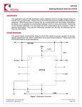
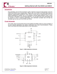
1
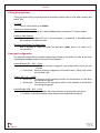
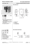
AN 022
Getting Started with the KXTE9
Introduction
This application note will help developers quickly implement proof-of-concept designs using the
KXTE9 tri-axis accelerometer.
Please refer to the KXTE9 data sheet for additional
implementation guidelines. While Kionix strives to ensure that our accelerometers will meet
design expectations by default, it is not possible to provide default settings to work in every
environment. Depending on the intended application, it is very likely that some customization will
be required in order to optimize performance. We hope the information provided here will help
the developer get the most out of the KXTE9.
Circuit Schematic
This section shows recommended wiring for the KXTE9, based on proven operation of the part.
Specific applications may require modifications from these recommendations. Please refer to the
KXTE9 Data Sheet for all pin descriptions.
I/O Vdd
SDA
1.5KΩ
1.5KΩ
10
IO Vdd
NC
1
9
2
8
SCL
NC
KXTE9
NC
3
7
4
6
INT
NC
5
0.1µF
Vdd
Figure 1: Application Schematic
36 Thornwood Dr. – Ithaca, NY 14850
tel: 607-257-1080 – fax: 607-257-1146
www.kionix.com - [email protected]
© 2015 Kionix, Inc.
10 July 2015
Page 1 of 9
AN 022
Quick Start Implementation
Here we present three basic ways to initialize the part. These can vary based on desired
operation, but generally the initial operations a developer wants to do are: read back acceleration
data, activate the tilt position function, and activate the motion detection functions. These cursory
solutions are provided as a means for configuring the part to a known operational state. Note that
these conditions just provide a starting point, and the values may vary as developers refine their
application requirements.
Read Back Acceleration Data
- Write 0x98 to Control Register 1 to assert PC1 (Power Control bit) and set the Output
Data Rate to 40Hz.
Address
Value
Hex
Binary
Hex Binary
CTRL_REG1
0x1B
0001 1011 0x98 1001 1000
Acceleration data can now be read from the XOUT, YOUT, and ZOUT registers.
Register Name
-
Activate Tilt Position Function
- Write 0x04 to Tilt Timer. Here we assume a 100ms timer will be sufficient (this is
based on an Output Data Rate of 40Hz).
- Write 0x99 to Control Register 1 to assert PC1 and TPE (Tilt Position Enable bit), and
set the Output Data Rate to 40Hz.
Register Name
TILT_TIMER
CTRL_REG1
-
Address
Hex
Binary
0x28
0010 1000
0x1B
0001 1011
Value
Hex Binary
0x04 0000 0100
0x99 1001 1001
Changes to tilt position state will now be reflected in bit 4 of STATUS_REG (INT bit),
bit 0 of INT_SRC_REG1 (TPS bit), TILT_POS_CUR, and TILT_POS_PRE registers,
and also on the physical interrupt pin.
Activate Motion Detection Functions
- Write 0x04 to WUF (Wake Up Function) Timer (100ms based on an Output Data Rate
of 40Hz).
- Write 0x03 to B2S (Back to Sleep) Timer (1200ms based on an Output Data Rate of
40Hz).
- Write 0x9E to Control Register 1 to assert PC1 (Power Control bit), WUFE (Wake Up
Function Enable bit), and B2SE (Back to Sleep Function Enable bit), and set the
Output Data Rate to 40Hz.
Register Name
WUF_TIMER
B2S_TIMER
CTRL_REG1
-
Address
Hex
Binary
0x29
0010 1001
0x2A
0010 1010
0x1B
0001 1011
Value
Hex
0x04
0x03
0x9E
Binary
0000 0100
0000 0011
1001 1110
Changes to motion status will now be reflected in bit 4 of STATUS_REG (INT bit), bits
1 and 2 of INT_SRC_REG1 (WUFS and B2SS bits), and INT_SRC_REG2 (motion
direction) registers, and also on the physical interrupt pin.
© Kionix 2015
10 July 2015
Page 2 of 9
AN 022
Timing Requirements
There are several timing requirements that developers should keep in mind when working with
the KXTE9.
I²C Clock
The I²C Clock can be up to 400Khz.
Power Up to Communication
After the part is powered up, it takes 110ms before it is ready for I²C communication.
Enable to Valid Outputs
After the part is enabled (PC1 bit in Control Register 1 is asserted), it takes 5ms before
the acceleration outputs are valid.
Software Reset/Power On Reset Delay
After a Software or Power On Reset, the part takes 100ms before it is ready for I²C
communication.
Interrupt Configuration
The physical interrupt has 8 possible configurations, based on two states for each of the three
customizable variables located in Interrupt Control Register 1:
Latched/Pulsed (IEL – bit 2 – 0x04)
0 – Latched mode – When an interrupt is triggered, it will remain active on the pin until
cleared.
1 – Pulse mode – When an interrupt is triggered, it will cause a short (~50µs) pulse on the
pin and clear itself.
Polarity (IEA – bit 3 – 0x08)
0 – Active Low – The interrupt pin will normally be HIGH, but will transition to LOW when
an interrupt is triggered.
1 – Active High – The interrupt pin will normally be LOW, but will transition to HIGH when
an interrupt is triggered.
Enable/Disable (IEN – bit 4 – 0x10)
0 – Disabled – Interrupt conditions will not be reflected on the physical interrupt pin.
1 – Enabled – Interrupt conditions will be reflected on the physical interrupt pin.
© Kionix 2015
10 July 2015
Page 3 of 9
AN 022
A Few Interrupt Tips
Read the Interrupt Release Register to Clear
In latched mode, the INT_REL register must be read in order to clear the physical interrupt
pin. This will also clear the Interrupt Source Registers (1 and 2) and the INT bit (0x10) in
the Status Register.
Microcontroller/GPIO Interrupt Handling
GPIO configuration is based solely on the connected hardware. The KXTE9 can be
configured to issue interrupts depending on how the GPIO is programmed to catch them
(if this is not the case, please contact your Kionix Sales Representative). Generally, when
an interrupt is triggered, the developer should take the following steps:
1- Disable GPIO interrupt
2- Clear GPIO interrupt and generate desired functionality
3- Enable GPIO interrupt
These steps should be taken without calling any I²C transactions if done in an interrupt
context, because the operating system or kernel will not allow busy-waiting on an I/O
operation during an interrupt service routine.
Interrupt Polling
If physical interrupts are not used, a polling mechanism can be devised, which checks the
INT bit in STATUS_REG. This mechanism should then look at INT_SRC_REG1 and
INT_SRC_REG2 to determine which engine caused the interrupt and what steps should
be taken before clearing the interrupt source information by reading the INT_REL register.
© Kionix 2015
10 July 2015
Page 4 of 9
AN 022
Digital Engine Operation
Motion Detection
The Wake Up Function and the Back to Sleep Function operate together. In later parts like the
KXTF9 these are combined into one function, but on the KXTE9 they must both be activated at
once in order to operate properly.
Axis Masking
It is possible to mask all wake-up/back-to-sleep events which occur on a particular axis (or
axes). This is done with the three bits: XBW, YBW, and ZBW in the Interrupt Control
Register 2.
XBW (bit 7 – 0x80)
0 – Events in the X axis are masked and will not generate an interrupt.
1 – Events in the X axis are unmasked and will generate an interrupt.
YBW (bit 6 – 0x40)
0 – Events in the Y axis are masked and will not generate an interrupt.
1 – Events in the Y axis are unmasked and will generate an interrupt.
ZBW (bit 5 – 0x20)
0 – Events in the Z axis are masked and will not generate an interrupt.
1 – Events in the Z axis are unmasked and will generate an interrupt.
Timers and thresholds
WUF (Wake Up Function) Timer – This timer establishes the number of Active Mode ODR cycles
that the acceleration on an unmasked axis must be above the WUF threshold before a wake up
interrupt is triggered. Each count in this register equals one cycle of the Active Mode ODR, as
dictated by OWUFA and OWUFB in Control Register 3.
WUF (Wake Up Function) Threshold – This threshold determines how much acceleration is
required in an unmasked axis in order to trigger a wake up interrupt that causes the part to
transition from inactivity to activity.
B2S (Back to Sleep) Timer – This timer establishes the number of Inactive Mode ODR cycles that
the change in acceleration on an unmasked axis must be below the B2S threshold before a back
to sleep interrupt is triggered. Each count in this register equals 16 cycles of the Inactive Mode
ODR, as dictated by OB2SA and OB2SB in Control Register 3.
B2S (Back to Sleep) Threshold – This threshold determines the change in acceleration required
on an unmasked axis in order to trigger a back to sleep interrupt that causes the part to transition
from activity to inactivity.
© Kionix 2015
10 July 2015
Page 5 of 9
AN 022
Tilt Position Function
Position Nomenclature and Reporting
Tilt Position Current – Indicates the current tilt position of the device. Defaults to 0x20 (left).
Tilt Position Previous – Indicates the previous tilt position of the device. Defaults to 0x20 (left).
Orientation
If the part is set on its edge with the part number facing the user, and the pin 1 indicator is
oriented so that it is in the top-left corner, the part is in the Y+ or “UP” position. If the user
then turns the part 90º counter-clockwise so that pin 1 is in the bottom left corner, it will be
in the X+ or “RIGHT” position. Continued rotation of the part counter-clockwise results in
the Y- or “DOWN” position when pin 1 is in the bottom right corner, and X- or “LEFT” when
pin 1 is in the top right corner. Setting the part on a flat surface with the part number and
pin 1 indicator facing the sky results in the Z+ or “FACE-UP” state. Likewise, flipping the
part over to expose the physical pins to the sky would be the Z- or “FACE-DOWN” state.
Y+
X+
Y-
X-
+Y
Pin 1
+X
Up Right Down Left
(UP) (RI) (DO) (LE)
Z+
Top
Bottom
Face-up
(FU)
ZTop
Bottom
Face-down
(FD)
+Z
1g
State Masking
Each of the 6 possible tilt position states can be masked using Control Register 2. To
mask an entire axis, both possible states for that axis will have to be masked. Note that to
mask a state, the bit associated with that state needs to be set to 0.
Timers and thresholds
Tilt Timer – This timer establishes the number of ODR cycles that a new tilt state must be active
before an interrupt is triggered and the position registers are updated.
Tilt Angle – The tilt engine uses acceleration due to gravity to determine tilt position state. As
such, it is unable to determine the rotational position of the part when the Z axis is in parallel with
the direction of gravitational acceleration. This state (for the purposes of the Tilt Angle variable)
is referred to as zero degrees. The Z axis must be a certain angle away from the direction of
gravity in order for tilt changes to be registered on the X and Y axes. The Tilt Angle register is
used to tell the engine at what angle it needs to start looking at X and Y axis acceleration instead
of Z.
© Kionix 2015
10 July 2015
Page 6 of 9
AN 022
Troubleshooting
All Interrupt Issues
- Make sure the KXTE9 is configured to issue interrupt signals in the way that your GPIO is
programmed to handle them.
- An oscilloscope on the physical interrupt pin can be a valuable tool to confirm physical
interrupt operation.
- Double check the Tilt Position State Mask bits in Control Register 2 (Tilt Position Function)
and/or the axis mask bits in Interrupt Control Register 2 (Back to Sleep and Wake-up
Functions).
- The Tilt Timer, WUF Timer, and B2S Timer are based on the Output Data Rate (dictated
by ODRA and ODRB in Control Register 1), so make sure the correct cycle time is used
when calculating the expected timer length.
Tilt Interrupt Not Working
- Make sure that the Tilt Position engine is enabled.
- Try shortening the timer requirements and make sure the next state transition does not
occur until after the expiration of the Tilt Timer.
- Try increasing the Tilt Angle to ensure that the engine can see the transition between the
X and Y axes and the Z axis (this should not be necessary if using the default value for Tilt
Angle, but it’s worth looking into if problems continue).
WUF (Wake Up Function) Interrupt Not Working
- Make sure that the WUF and B2S engines are both enabled.
- Try altering the threshold requirements to achieve desired operation. If the part is waking
up too easily, try increasing the threshold. If the interrupt is not firing at all, the threshold
may be set too high.
- Try shortening the timer requirements, and make sure the acceleration on an unmasked
axis is above the threshold until the expiration of the WUF Timer.
- Make sure the Back to Sleep interrupt has been triggered before trying to activate the
wake up function. The part cannot wake up unless it has first entered a sleep state
through the Back to Sleep function.
B2S (Back to Sleep) Interrupt Not Working
- Make sure that the WUF and B2S engines are both enabled.
- Try altering the threshold requirements to achieve desired operation. If the part is going
back to sleep too easily, try reducing the threshold. If the interrupt is not firing at all, the
threshold may be set too low. Note that the Back to Sleep Threshold is based on the
difference between consecutive acceleration samples, and can be triggered based on
acceleration data from any unmasked axis. Once the difference between two consecutive
samples is less than B2S_THRESH, the timer starts and continues counting until it
expires (the part goes to sleep) or a sample from the same axis that triggered the timer is
more than B2S_THRESH away from the first of the two samples that triggered the timer
(the part does not go to sleep, and the timer is reset).
- Try shortening the timer requirements and make sure the acceleration change on an
unmasked axis is less than the threshold for the duration of the timer.
- Remember, each count in the B2S_TIMER Register is equal to 16 cycles of the Inactive
Mode ODR, as dictated by OB2SA and OB2SB in Control Register 3.
© Kionix 2015
10 July 2015
Page 7 of 9
AN 022
Accelerometer USB Development Kit
Kionix offers an Accelerometer USB Development Kit that can be used to quickly begin the
development of applications and firmware that incorporate Kionix accelerometers including the
KXTE9. The Development Kit provides a common interface to Kionix evaluation boards. For
additional information regarding the development kit please refer to the Kionix Application
Firmware Development Kit user’s manual. Here is a brief description of the applications and
utilities supported by the development kit:
SensorScope
This application allows the user to monitor data coming from the attached sensor. This data can
be saved to a file or viewed in real time. With only two verification steps, the application will begin
immediately displaying a series of graphs representing the acceleration with respect to time.
SensorScope can be used to measure the noise of the accelerometer. Here are the steps that
need to be followed to measure noise:
-
-
-
-
-
Place the evaluation board on a flat surface in the desired orientation.
To change the application settings, select Settings from the Edit menu. Using this menu
the user can change the following:
Sampling Rate – The rate (in Hz) at which the software queries the accelerometer
for axis data.
Realtime Interval – The amount of data (in milliseconds) the software will buffer
and display in real time.
Select the capture button. The application will begin capturing data immediately. Captured
data is written to a file, and will not be viewable until after the capture has finished. The
status bar is used to notify the user of a capture in progress.
The application will continue to collect data until the user clicks the Stop button, or the
resulting capture file has exceeded the file size limits (~1Gigabyte). We recommend
collecting the data for at least 120 seconds.
Captured data will be saved as a list of comma-separated values (.csv). Each entry in the
list is comprised of a time, followed by the raw count for each axis (x, y, and z
respectively).
Select Save or Save As from the File menu to save the file.
Open the saved file using Excel. Calculate the average of the samples. This gives the
noise of the accelerometer in raw counts.
SensorCalc
This application allows the user to test and calculate the zero-g offset and sensitivity parameters
of the accelerometer. Once the accelerometer is properly placed relative to the Earth’s gravity,
simple mouse clicks initiate a series of test sequences that result in the display of raw-count data.
SensorMap
This application allows the user to read and write to specific registers of the accelerometer. The
registers, and their values, are all displayed simultaneously on one color-coded grid.
© Kionix 2015
10 July 2015
Page 8 of 9
AN 022
Motion
This utility allows the user to test if the accelerometer has detected motion on any of the axes.
The user has options to change the WUF_THRESH and WUF_TIMER register values and also
mask any of the axes.
Rotation
This utility allows the user to monitor the orientation of the accelerometer. It can be used to check
if the accelerometer is in the face-up, face-down, left, right, up or down orientations. The user has
options to change the TILT_TIMER and TILT_ANGLE register values and also mask any of the
axes.
The Kionix Advantage
Kionix technology provides for X, Y, and Z-axis sensing on a single, silicon chip. One accelerometer can
be used to enable a variety of simultaneous features including, but not limited to:
Hard Disk Drive protection
Vibration analysis
Tilt screen navigation
Sports modeling
Theft, man-down, accident alarm
Image stability, screen orientation & scrolling
Computer pointer
Navigation, mapping
Game playing
Automatic sleep mode
Theory of Operation
Kionix MEMS linear tri-axis accelerometers function on the principle of differential capacitance.
Acceleration causes displacement of a silicon structure resulting in a change in capacitance. A signalconditioning CMOS technology ASIC detects and transforms changes in capacitance into an analog
output voltage, which is proportional to acceleration. These outputs can then be sent to a microcontroller for integration into various applications.
For product summaries, specifications, and schematics, please refer to the Kionix MEMS accelerometer
product sheets at http://www.kionix.com/parametric/Accelerometers.
© Kionix 2015
10 July 2015
Page 9 of 9