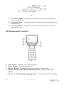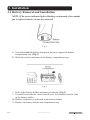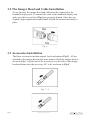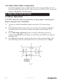
1
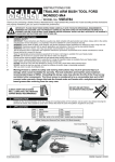
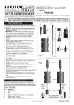
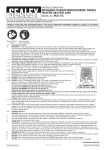
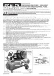
Instructions for: video borescope Model No. VS8196.v2 Thank you for purchasing a Sealey product. Manufactured to a high standard this product will, if used according to these instructions and properly maintained, give you years of trouble free performance. IMPORTANT: PLEASE READ THESE INSTRUCTIONS CAREFULLY. NOTE THE SAFE OPERATIONAL REQUIREMENTS, WARNINGS AND CAUTIONS. USE THIS PRODUCT CORRECTLY AND WITH CARE FOR THE PURPOSE FOR WHICH IT IS INTENDED. FAILURE TO DO SO MAY CAUSE DAMAGE AND/OR PERSONAL INJURY AND WILL INVALIDATE THE WARRANTY. PLEASE KEEP INSTRUCTIONS SAFE FOR FUTURE USE. Table of Contents 1. Safety Instructions. ..............................................................................2 1.1 Work Area Safety.......................................................................2 1.2 Electrical Safety.......................................................................... 2 1.3 Personal Safety. ..........................................................................3 2. Description, Specifications................................................................4 2.1 Description. .................................................................................. 4 2.2 Specifications............................................................................... 4 2.3 Accessories Included.................................................................5 2.4 Buttons and Controls. ..............................................................6 3. Installation. ....................................................................................................... 7 3.1 Battery Removal and Installation.......................................7 3.2 The Imager Head and Cable Installation. .......................8 3.3 Accessories Installation. ..........................................................8 3.4 Video-Out Cable Connection................................................ 9 4. Operation Instructions............................................................................... 9 4.1 Basic Operation.......................................................................... 9 4.2 Operation Precautions...........................................................10 4.3 Battery Precautions. ............................................................... 11 4.4 Maintenance Instructions..................................................... 11 5. Troubleshooting. ...........................................................................................12 Page 1 Original Language Version VS8196.V2 Issue: 1 - 14/12/11 6. Warranty Information...................................................................... 12 6.1 Service Procedures..................................................................12 7. Environmental protection. ........................................................... 13 8. Declaration of Conformity........................................................... 14 1. Safety Instructions 1. Safety Instructions IMPORTANT: Failure to understand and follow the instructions listed below may result in electric shock, fire and/or serious personal injury. 1.1 Work Area Safety • • • • • • • • • • Always perform automotive testing in a safe environment. Keep your work area clean and well lit. Cluttered benches and dark areas may cause accidents. Keep clothing, hair, hands, tools, test equipment, etc. away from all moving or hot engine parts. Operate the tool in a well-ventilated work area. Do not operate the tool in explosive atmospheres, such as in the presence of flammable liquids, gases, or heavy dust. Keep a fire extinguisher suitable for gasoline/chemical/electrical fires nearby. Do not use the tool around corrosive chemicals which can damage the tool. Do not abuse the cable. Never use the cable to carry the tool. Keep bystanders, children and visitors away while operating the tool. Keep the tool dry, clean, free from oil, water and grease. Use a mild detergent on a clean cloth to clean the outside of the tool when necessary. 1.2 Electrical Safety • • • Page 2 Avoid body contact with earthed or grounded surfaces such as pipes, radiators, ranges and refrigerators. Do not expose the tool to rain or wet conditions. Water entering the tool will increase the risk of electric shock. Do not abuse the cable. Never use the cable for carrying, pulling, or unplugging the tool. Keep cable away from heat, oil, sharp edges or moving parts. Original Language Version VS8196 Issue: 1 - 01/07/10 1.3 Personal Safety • • • • • • • Page 3 Do not use the tool while tired or under the influence of drugs, alcohol, or medications. A moment of interruption can result in serious personal injury. Do not over-reach. Keep proper footing and balance at all times. Proper footing and balance enables better control of the tool in unexpected situations. Always wear safety eye protection that meets ANSI standards. Do not place the tool on any unstable surface. The tool may fall causing serious injury to a person or serious damage to the tool itself. Never spill liquid on the display units. Liquid increases the risk of electric shock and damage to the tool. Do not use the tool for personal or medical use in any way. The product is not shock-resistant. Do not use it as a hammer or drop it. Original Language Version VS8196.V2 Issue: 1 - 14/12/11 2. Description / Specification 2.1 Description Versatile video borescope with Ø8.5mm x 1000mm semi-rigid probe. Image displayed on a crystal clear, 60mm high resolution LCD display with on-screen horizontal/vertical flip features for use with side-view mirrors. CMOS camera with adjustable LED for fine control of light output and clear pictures. Suitable for internal inspection of cylinder bores and vehicle compartments/components. Quickest and most cost effective solution, ideal for the inspection of engines, machinery, buildings and infrastructure. Supplied with AV cable for external viewing of image. Uses 4 x AA batteries. 2.2 Specifications Recommended use Minimum viewing distance Indoor 25mm (1”) Image controls Low light vision Lighting 1 fully adjustable LED Screen type display Display resolution 2.4” TFT LCD 234 x 480 Power supply 4 alkaline AA, 1.5Volt batteries Cable reach 1m (3’) -- expandable to 5m (16’) Imager head diameter 8.5mm (0.22”) Operating temp. Main unit: 32°F to 113°F (0°C to 45°C); Cable: 14°F to 176°F (-10°C to 80°C) Storage temp. -4°F to 158°F (-20°C to 70°C) Operating humidity 5% to 95% non-condensing (display unit) Page 4 Original Language Version VS8196 Issue: 1 - 01/07/10 2.3 Accessories Included 1) User’s Manual 2) Imager head and cable 3) Magnet, hook and mirror 4) Video-out cable 5) 4xAA batteries 6) Protective case Note: Because of continuing improvements, actual product may differ slightly from picture. Fig. 1 1) 2) 3) 4) 5) 6) Page 5 Handheld Display Unit – Ergonomic tool with comfortable pistol grip design. Imager Head and Cable – Connects to the tool while in use to view images and videos. Cable Connector – Connects the handheld display unit to the imager head and cable. Power Indicator Light – Illuminates once the tool is turned on. Video-Out Port – To connect to a TV / monitor. Battery Compartment Cap – Remove to install or remove batteries. Original Language Version VS8196.V2 Issue: 1 - 14/12/11 Fig. 2 7) 8) 9) Accessory Magnet – Picks up metal objects such as dropped rings or screws on the floor. Accessory Hook – Unclogs obstacles and picks up wires in the pipes or confined areas. Accessory Mirror – Helps users look around corners and see inside unreachable areas. 2.4 Buttons and Controls Fig. 3 A. LCD Screen – Backlit, 234 x 480 resolution. B.Power Button – Turns the tool on/off. C. Reverse Button - Controls the direction of the real-time image. D. DOWN Arrow LED Lighting Adjusting Button – Adjusts dim LED lighting. E. UP Arrow LED Lighting Adjusting Button – Adjusts bright LED lighting. Page 6 Original Language Version VS8196 Issue: 1 - 01/07/10 3.Installation Installation 3. 3.1 Battery Removal and Installation NOTE: If the power indicator light is blinking continuously, this reminds you to replace batteries in time as instructed. Fig. 4 1) Turn the handheld display unit upside down to expose the battery compartment cap. (Fig.4) 2) Slide the catch in and remove the battery compartment cap. Fig. 5 Pull out the battery holder and remove batteries. (Fig.5) To install new batteries, insert four (4) new AA batteries into the slots in the battery holder. 4) Battery orientation is indicated in the battery holder. 5) Replace the battery holder and compartment cap. Page 7 Original Language Version VS8196.V2 Issue: 1 - 14/12/11 3.2 The Imager Head and Cable Installation To use the tool, the imager head and cable must be connected to the handheld display unit. To connect the cable to the handheld display unit, make sure the key and slot (Fig.6) are properly aligned. Once they are aligned, finger-tighten the knurled knob to hold the connection firmly in place. Fig. 6 3.3 Accessories Installation The three accessories include magnet, hook and mirror (Fig.2). All are attached to the imager head in the same manner. Hold the imager head as shown in Fig.7, slip the end of the accessory over the flats of the imager head and then rotate the accessory 90° to fix as shown in Fig.8. Fig. 7 / 8 Page 8 Original Language Version VS8196 Issue: 1 - 01/07/10 3.4 Video-Out Cable Connection Insert the supplied video-out cable into the video-out port of the tool, and the other end of the cable into the video-in port of a TV, the LCD screen will output a high quality real-time image. 4. 4.Operation OperationInstructions Instructions 4.1 Basic Operation CAUTION: Keep the cable away from heat, oil, sharp edges or moving parts. Replace damaged cables immediately. 1) 2) 3) 4) To turn on, hold the handheld display unit with LCD screen facing you. Press Power button to turn on the screen. The power indicator light will illuminate green. The real-time image will appear on the display LCD screen. Press LED Light Adjusting buttons to adjust LED light intensity as needed. Press DOWN arrow button to dim LED, press UP arrow button to brighten LED. Press Reverse button to control the direction of the real-time image. The real-time image will do a horizontal reverse or vertical reverse. (Fig.9) Page 9 Fig. 9 . Original Language Version VS8196.V2 Issue: 1 - 14/12/11 4.2 Operation Precautions CAUTION: Do not insert the tool into anything or anywhere that may contain a live electrical charge. yy yy yy yy yy yy yy yy yy yy yy yy yy yy Do not operate the tool unless the user’s manual has been read thoroughly and proper training has been completed. Do not immerse the handheld display unit in water. Reduce the risk of electric shock and damage. Do not use the tool if condensation forms inside the imager head. Let the water evaporate before using again. Do not use excessive force to insert or withdraw the cable. Do not use the imager head and cable to modify surroundings, clear pathways or clogged areas. The handheld display unit is not waterproof. The imager head and its cover are waterproof, but not acid-proof or fireproof. Avoid submersing the imager head into corrosive, oily places and be sure to keep the imager head away from high temperature objects. Do not put the imager head and cable into anything or anywhere that may contain a live electrical charge. Store idle components out of the reach of children and other untrained persons. Maintain the tool with care. Properly maintained tools are less likely to cause injury. If the tool is dropped, check for the breakage and any other conditions that may affect its operation. manufacturer of the tool. Dry your hands when operating the tool or replacing batteries. Protect against excessive heat. The tool should be kept away from heat sources such as radiators, stoves or others that produce heat. Store the tool in ventilated and dry places. Page 10 Original Language Version VS8196 Issue: 1 - 01/07/10 NOTE: Please check following methods to avoid injury. FOR WALLS: For inspecting the wall cavities, ensure you turn off the circuit breaker to the whole premises before using the tool. FOR PIPES: If you suspect a metal pipe could contain a live electrical voltage, have a qualified electrician check the pipe before using. FOR AUTOMOBILES: Ensure the automobile is not running during inspection. Metal and liquid under the bonnet may be hot. Don’t get oil or fuel on the imager head. 4.3 Battery Precautions yy yy yy yy yy yy Remove the batteries while cleaning the tool. Remove the batteries before storing the tool for a long period of time to prevent battery leakage from damaging battery compartment. When necessary, replace all four (4) batteries with new ones. Use only the size and type of batteries specified. Be sure to install batteries with the correct polarity as indicated in the battery compartment. Properly dispose of batteries. Exposure to high temperatures can cause batteries to explode. Do not dispose in fire. 4.4 Maintenance Instructions NOTE: Make sure the batteries have been removed from the tool before performing maintenance. yy yy yy yy yy yy yy yy Page 11 Tool maintenance must be performed by qualified repair personnel. When maintaining, use only identical replacement components. Do not attempt to take apart unless directed by the manual. Follow instructions to replace accessories. Do not use acetone to clean the tool. Instead, use alcohol. Avoid rubbing too hard on the LCD screen. After using, wipe the display unit clean with a dry cloth. Stop using the tool if it starts smoking or emitting noxious fumes. Always handle the tool with care. It is not shock-resistant and should not be banged or dropped. Do not disassemble the tool beyond what is shown in the manual. Doing so will void your warranty. Original Language Version VS8196.V2 Issue: 1 - 14/12/11 5. 5.Troubleshooting Troubleshooting SYMPTOMS Display unit is on, but does not show image. POSSIBLE REASONS SOLUTIONS Cable connection is loose. Check and reattach. Imager head is dirty. Clean imager head. LEDs on imager head are dim at max brightness, display changes between black/white and color, display turns itself OFF after a short period. Batteries are low. The tool will not turn on. Dead batteries. Replace batteries. Replace batteries. 6.Limited Warranty 6. OneInformation Year Warranty Sealey warrants to its customers that this product will be free from all defects in materials and workmanship for a period of one (1) year from the date of the original purchase, subject to the following terms and conditions: 1) The sole responsibility of Sealey under the Warranty is limited to either the repair or, at the option of Sealey, replacement of the tool at no charge with Proof of Purchase. The sales receipt may be used for this purpose. 2) This warranty does not apply to damages caused by improper use, accident, flood, lightning, or if the product was altered or repaired by anyone other than the Manufacturer’s Service Centre. 3) Sealey shall not be liable for any incidental or consequential damages arising from the use, misuse, of the tool. 4) All information in this manual is based on the latest information available at the time of publication and no warranty can be made for its accuracy or completeness. Sealey reserves the right to make changes at any time without notice. 6.1 Service Procedures If you have any questions, please contact your local store, distributor or visit our website at www.sealey.co.uk. If it becomes necessary to return the tool for repair, contact your local distributor for more information. Page 12 Original Language Version VS8196 Issue: 1 - 01/07/10 Environmental Protection. Recycle unwanted materials instead of disposing of them as waste. All tools, accessories and packaging should be sorted, taken to a recycle centre and disposed of in a manner which is compatible with the environment. When the product is no longer required, it must be disposed of in an environmentally protective way. Contact your local solid waste authority for recycling information. Battery Removal. Open the rear cover as in 3.1. Remove the batteries. Replace the cover. Dispose of batteries according to local authority guidelines. Under the Waste Batteries and Accumulators Regulations 2009, Jack Sealey Ltd are required to inform potential purchasers of products containing batteries (as defined within these regulations), that they are registered with Valpak’s registered compliance scheme. Jack Sealey Ltd’s Batteries Producer Registration Number (BPRN) is BPRN00705 NOTE: It is our policy to continually improve products and as such we reserve the right to alter data, specifications and component parts without prior notice. IMPORTANT: No liability is accepted for incorrect use of this product. WARRANTY: Guarantee is 12 months from purchase date, proof of which will be required for any claim. INFORMATION: For a copy of our latest catalogue and promotions call us on 01284 757525 and leave your full name and address, including postcode. Sole UK Distributor, Sealey Group, Kempson Way, Suffolk Business Park, Bury St. Edmunds, Suffolk, IP32 7AR Page 13 Original Language Version 01284 757500 01284 703534 Web email www.sealey.co.uk [email protected] VS8196.V2 Issue: 1 - 14/12/11