1
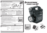
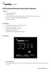
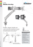
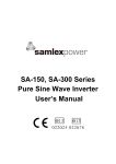
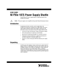
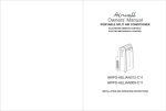
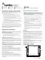
Toll Free Numbers
Ph: 1.800.561.5885
Fax: 1.888.814.5210
Local Numbers
Ph: 604.525.3836
Fax: 604.525.5221
Description, features & applications
IDC-360 Series offer 360W capacity Isolated DC-DC Converter models covering wide
range of DC input voltages of 12V / 24V / 48V / 72V and outputs of
12V / 24V / 48V. Design features include:
- Advanced Switch Mode Technology with fixed frequency PWM control for
optimum efficiency and reliability and compact size
- Galvanic isolation between input and output sides with following benefits:
- Noise on the input side is isolated from the output side for noise sensitive
loads like radios, instrumentation, data processing etc.
- Converts Positive voltage to Negative voltage with respect to common, noninsulated ground. For example, IDC-360C-12 can convert - 48VDC of telecom
supply to +12VDC supply
- Can be used to create either Negative isolated or Positive isolated Rail using
single unit or dual Positive and Negative isolated Rails using 2 units in series.
− Protections against short circuit / overload, input over voltage / transients, output
over voltage, over heating and reverse polarity;
− Compliance with European EMI / EMC and Automotive Standards
Applications include noise sensitive loads like radios, instrumentation and data
processing for isolated input and output grounds and telecom, tractor trailers, buses,
forklifts, heavy machinery, locomotive / railroad, marine and aviation for non-isolated,
common input and output ground. For detailed information, please read
Application Note titled “Isolated DC-DC Converters” under online Support
Section at www.samlexamerica.com.
INSTALLATION & OPERATION
WARNING! This unit is NOT a Battery Charger. Please do not use it to charge a battery.
General Installation Requirements
-
-
-
IDC-360
Instructional Manual
Head Office
103 - 4268 Lozells Avenue
Burnaby, BC, V5A 0C6, Canada
The unit is cooled by a temperature controlled fan. Install the unit in a cool,
dry & well ventilated space. Do not block fan vent openings on the sides.
Do not install the unit inside engine compartment.
Do not connect / disconnect input and output connections when live voltages
are present.
Fusing on the Input & Output Sides
The input side of the unit will be connected to the battery. A battery has the capacity to
supply very large currents. In case there is a short circuit between the input side wiring, very
heavy current will flow and will burn / melt the wiring and may be a fire hazard. To prevent
this, use a suitable fast blow fuse (see Table 1) in line with the Positive input wire within 7"
from the battery Positive terminal. The output side should be connected through a suitable
fuse in line with the "Output +" terminal (see Table 2).
WARNING! The Warranty will be voided if proper fuse is not used as recommended.
Switching On & Switching Off Arrangement on the Input Side
There is no on/off switch on the input side of the unit. An external on/off switch may
be used in series with the Positive input wire, if required.
Sizing of Input and Output Wiring
In order to prevent excessive voltage drop and consequent loss of current capacity and
efficiency, use proper size of input and output wires. Please note that as the current /
length of wiring are increased, the thickness of the wiring will also be required to be
increased. The thickness of wires and cables is normally expressed in AWG (American Wire
Gauge). Also, note that a lower AWG number denotes a thicker wire. Use multi-stranded
copper insulated wiring rated for at least 90oC / 194oF. Please refer to details of input/
output wire sizes (Tables 1 & 2).
Making Input & Output Connections & Operation
CAUTION! Please ensure that the polarity of the input connection is not reversed.
Connect the Positive of the battery to the Positive terminal and the Negative of the
battery to the Negative. In case the input polarity is reversed, the unit will be damaged
and will not be covered under Warranty.
-
Input and output connections should not be made when live voltages are
present.
-Switch off the load that is required to be powered from the converter.
- Connect the output wires to the load and then to the output side of the unit
through the external fuse. Observe correct polarity.
-Switch off the external inline input side switch (if used) and also remove the
external inline fuse in the Positive input wire.
- Connect the input side wires to the converter’s input side first. Observe
correct polarity.
- Connect the input wires to the battery.
- Insert the external inline input side fuse in the Positive input wire. NOTE: If an
on/off switch is not used in series with the Positive input wire or if a switch
has been used and has not been switched off, a spark may be observed when
inserting the fuse due to the initial inrush current to charge the input side
capacitors inside the converter.
- Switch on the input power to the unit (if an external switch has been used).
Output voltage will now be available on the output side of the unit.
-Switch on the load.
Protections
Overload/Short Circuit: Overloading beyond the maximum output current value
(30A for IDC-360x-12, 15A for IDC-360x-24 & 7.5A for IDC-360x-48) will produce
voltage drop on the output side. The output will recover automatically once the
overload condition is removed. Under short circuit conditions on the output side, the
voltage will drop to a very low value, output current will rise beyond the rated value
and external fuse will blow if short circuit condition persists for longer duration. There
is automatic reset if the short circuit condition is removed before the fuse blows. Over Voltage On The Output Side: In case of over voltage, a zener diode across the
output will conduct and simulate short circuit protection (see above).
Over Voltage / Transients On The Input Side: A Metal Oxide Varistor (MOV) across the
input terminals provides protection against high voltage transients by blowing the internal
input side fuse(s) / external fuse(s).
Reversal Of Polarity On The Input Side Connection: In case of reversal on input side
polarity, a diode connected across the input terminals will conduct and will blow the
internal input side fuse(s) / external fuse(s).
Over Temperature: In case of over heating, the output voltage will drop. It will reset
automatically once the temperature drops to normal.
DIMENSIONS & LAYOUT
Height: 83 mm
5
132.8
91
BACK
SIDE
FRONT
SIDE
Type of Input and Output Connections
The unit has a terminal block with 4 male, quick connect flat blade type terminals
(6.3 mm / ¼ in.) for quick connection/disconnection (see Fig 2). Two blades are for input
(Marked “Input +” and “Input –”) and two are for output (Marked “Output -” and
“Output +”). The wiring for connection to the terminals should be terminated with the
corresponding female quick connect terminals meant for the above male 6.3 mm / ¼” flat
blade type terminal.
Note: All measurements are in millimetres.
181
190.5
Fig 1. Dimensions (Bottom View)
DC-DC Converter Manual
| 1
IDC-360 | Instructional Manual
DIMENSIONS & LAYOUT (continued)
TABLE 1.
External Input Side Fuse & Wiring
Model
Name
6
83
mm
1
2
3
4
Fuse Specs
WIRE SIZE
(see Note 1 below)
IDC-360A-12, 24
32V, 40A
AWG#10
IDC-360B-12, 24, 48
32V, 30A
AWG#10
IDC-360C-12, 24, 48
80V, 20A
AWG#12
IDC-360D-12, 24
125V, 10A
AWG#12
TABLE 2.
External Output Side Fuse & Wiring
Model
Name
5
91mm
LEGEND
1. Input +
2. Input 3. Output -
4. Output +
5. Chassis Ground
6. Fan Suction Vents
AT THE BACK (NOT SHOWN):
- Fan
- Fan Exhaust Vents
Fig. 2 Layout (Front View)
SPECIFICATIONS
Model
No.
OUTPUT
CURRENT (A)
IDC-360A-12
9 - 18
<40
12.5
30
IDC-360B-12
20 - 35
<30
12.5
30
IDC-360C-12
30 - 60
<20
12.5
30
IDC-360D-12
60 - 120
<10
12.5
30
IDC-360A-24
9 - 18
<40
24.5
15
IDC-360B-24
20 - 35
<30
24.5
15
IDC-360C-24
30 - 60
<20
24.5
15
IDC-360D-24
60 - 120
<10
24.5
15
IDC-360B-48
20 - 35
<30
48.0
7.5
IDC-360C-48
30 - 60
<20
48.0
7.5
INPUT TO OUTPUT ISOLATION
OUTPUT RIPPLE & NOISE
PEAK EFFICIENCY
COOLING
OPERATING TEMPERATURE
HUMIDITY, NON-CONDENSING
PROTECTIONS
< 25 mA
Yes. > 400V RMS
< 50 mV RMS
85%
By temperature controlled fan
-20 to +30oC / -4oF to 86oF
(de-rate linearly to zero at 70oC / 158oF)
Max 95%
Overload / short circuit on the output
side; Over voltage on the output side;
Over voltage / transients on the input
side; Reverse polarity on the input side;
Over heating
SAFETY AND EMC STANDARDS
Emission
EN50081-1 / EN61000-6-3
Immunity
EN50082-1 / EN61000-6-1
Automotive directive
INPUT / OUTPUT CONNECTIONS
DIMENSIONS (W x D x H) MM/INCH
WEIGHT (KG/LB)
WIRE SIZE
(see Note 1 below)
IDC-360A-12
32V, 30A
AWG#10
IDC-360B-12
32V, 30A
AWG#10
IDC-360C-12
32V, 30A
AWG#10
IDC-360D-12
32V, 30A
AWG#10
IDC-360A-24
32V, 15A
AWG#12
IDC-360B-24
32V, 15A
AWG#12
IDC-360C-24
32V, 15A
AWG#12
IDC-360D-24
32V, 15A
AWG#12
IDC-360B-48
58V, 7.5A
AWG#18
IDC-360C-48
58V, 7.5A
AWG#18
Note 1:
Input voltage MAX Input
Output
range (VDC) Current (A) Voltage (VDC)
NO LOAD CURRENT DRAW
Fuse Specs
95/54/EC
(IDC-360A & IDC-360B Series only)
Quick Connect male 6.3 mm /
1/4" flat blade
132.8 x 190.5 x 83 / 5.23 x 7.5 x 3.27
a) Wire sizes shown are based on 2% voltage drop over distance of 3' from input source
or load for current = Amp rating of the fuse.
b) For distances > 3', use thicker wires to limit voltage drop to <2% for current = Amp
rating of the fuse.
2 Year limited warranty
IDC-360 manufactured by Samlex America, Inc. (the “Warrantor“) is warranted to be
free from defects in workmanship and materials under normal use and service. The
warranty period is 2 years for the United States and Canada, and is in effect from the
date of purchase by the user (the “Purchaser“).
Warranty outside of the United States and Canada is limited to 6 months. For a
warranty claim, the Purchaser should contact the place of purchase to obtain a
Return Authorization Number.
The defective part or unit should be returned at the Purchaser’s expense to the
authorized location. A written statement describing the nature of the defect, the
date of purchase, the place of purchase, and the Purchaser’s name, address and
telephone number should also be included.
If upon the Warrantor’s examination, the defect proves to be the result of defective
material or workmanship, the equipment will be repaired or replaced at the
Warrantor’s option without charge, and returned to the Purchaser at the Warrantor’s
expense. (Contiguous US and Canada only)
No refund of the purchase price will be granted to the Purchaser, unless the
Warrantor is unable to remedy the defect after having a reasonable number of
opportunities to do so. Warranty service shall be performed only by the Warrantor.
Any attempt to remedy the defect by anyone other than the Warrantor shall render
this warranty void. There shall be no warranty for defects or damages caused by
faulty installation or hook-up, abuse or misuse of the equipment including exposure
to excessive heat, salt or fresh water spray, or water immersion.
No other express warranty is hereby given and there are no warranties which
extend beyond those described herein. This warranty is expressly in lieu of any other
expressed or implied warranties, including any implied warranty of merchantability,
fitness for the ordinary purposes for which such goods are used, or fitness for a
particular purpose, or any other obligations on the part of the Warrantor or its
employees and representatives.
There shall be no responsibility or liability whatsoever on the part of the Warrantor
or its employees and representatives for injury to any persons, or damage to
person or persons, or damage to property, or loss of income or profit, or any
other consequential or resulting damage which may be claimed to have been
incurred through the use or sale of the equipment, including any possible failure of
malfunction of the equipment, or part thereof. The Warrantor assumes no liability for
incidental or consequential damages of any kind.
1.4 / 3.1
NOTE: Specifications are subject to change without notice
Samlex America Inc. (the “Warrantor”)
www.samlexamerica.com
11004-IDC-360-0413
DC-DC Converter Manual
| 2