1
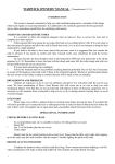
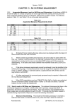
Packing Instruction RD 284
Issue 2
PACKING AND SERVICING INSTRUCTION
FOR THE IRVIN-GQ LTD
EMERGENCY PARACHUTE ASSEMBLY TYPE EB80
MRI IRV 844
Issue 2
Sep 02
Page (i)
Packing Instruction RD 284
Issue 2
AMENDMENT RECORD
1 All new material inserted by amendment action will be signified by vertical lines in margins indicating
the amended text or figure.
2 The page holding the amended material will be marked with the Amendment Number in the bottom left
hand corner.
Amdt No
Amended by
Date
1
2
3
4
5
6
7
8
9
10
11
12
13
14
15
16
17
18
19
20
Sep 02
Page (ii)
Packing Instruction RD 284
Issue 2
WARNINGS
YOU CAN SUBSTANTIALLY REDUCE THE RISK BY ENSURING THAT EACH
COMPONENT OF THE SYSTEM HAS BEEN ASSEMBLED AND PACKED IN STRICT
COMPLIANCE WITH THE MANUFACTURERS INSTRUCTIONS, BY OBTAINING PROPER
INSTRUCTION IN THE USE OF THIS SYSTEM, AND BY OPERATING EACH COMPONENT
OF THE SYSTEM IN STRICT COMPLIANCE WITH THIS INSTRUCTION MANUAL.
HOWEVER, PARACHUTE SYSTEMS SOMETIMES FAIL TO OPERATE EVEN WHEN
PROPERLY PACKED AND OPERATED SO THAT YOU RISK SERIOUS INJURY OR DEATH
EACH TIME YOU USE THE SYSTEM
NO RESPONSIBILITY WILL BE ACCEPTED BY THE COMPANY FOR INCORRECT
FUNCTIONING OF THIS ASSEMBLY:
(1)
IF NOT PACKED AS DETAILED IN THIS INSTRUCTION MANUAL
(2)
IF ANY UNAUTHORISED MODIFICATIONS HAVE BEEN CARRIED OUT ON
ANY PART OF THE ASSEMBLY.
(3)
RE-PACKING OF THIS ASSEMBLY MUST BE UNDERTAKEN BY A
CERTIFIED FAA/BPA RIGGER OR FOREIGN EQUIVALENT
(4)
REPAIR OF DAMAGED ASSEMBLIES MUST BE UNDERTAKEN BY EITHER
THE MANUFACTURER OR CERTIFIED FAA/BPA RIGGER OR FOREIGN
EQUIVALENT
LIFING LIMITATIONS
The finite life of the parachute assembly is 15 years from the date of manufacture subject to serviceability.
To ensure the continued safety it is essential that the parachute assembly and log card is returned to the
Irvin-GQ Ltd Quality Manager when it is 10 years old. Irvin-GQ Ltd will then undertake a thorough
inspection of the assembly and subject to its continuing good condition, revalidate it for its full life of 15
years.
Sep 02
Page (iii)
Packing Instruction RD 284
Issue 2
LIST OF CONTENTS
1
2
3
4
5
6
7
8
9
10
11
12
13
14
15
16
17
Amendment record
Important notes
List of contents
Introduction
DESCRIPTION
Parachute
Auxiliary parachute
Pack and harness
List of components
Material and packing aids
Preparing the auxiliary parachute
Preparing the parachute
Pleating the canopy
Folding the canopy
Stowing the ripcord handle
Stowing the rigging lines
Stowing the canopy
Closing the pack
Tidying the pack
Securing the lower ripcord pin
Completing the assembly
Appendix
A
Sep 02
Maintenance Instructions
Page (iv)
Packing Instruction RD 284
Issue 2
PACKING INSTRUCTIONS FOR THE IRVIN-GQ EMERGENCY PARACHUTE
ASSEMBLY TYPE EB80
INTRODUCTION
1
This document details the sequence of procedures to be carried out during the packing of the
Emergency Parachute Assembly Type EB80.
DESCRIPTION AND LIST OF COMPONENTS
PARACHUTE
2
The IRVIN Type H112/1 parachute used with this assembly features a bi-conical canopy and an
extended net skirt. The canopy is of block construction and comprises 20 gores, each made up of four
panels. The parachute is conventionally hem rigged with 20 rigging lines terminating at two lift webs.
Two control lines, attached to rigging lines No 3 and 18 respectively, provide the means of steering the
parachute.
AUXILIARY PARACHUTE
3
The auxiliary parachute comprises a helical coiled spring enclosed in net panels surmounted by a
circular canopy. The canopy and net panels are reinforced with tapes the ends of which are formed into a
loop to provide a means of attachment to the vent of the main parachute. The apex is fitted with a cap to
which a loop assembly, that forms part of the pack closure system, is assembled.
PACK AND HARNESS
4
The pack is integral with the harness and comprises a base and four flaps. Closure is by means of
three soft loops which pass through the pack and are retained by a ripcord pin system located centrally
under a protection flap at the outside wall of the pack base. The harness is of the three point closure type
incorporating a webbing chest strap and quickly adjustable buckles on the leg straps. The ripcord
assembly incorporates a non-crushable housing which is routed from the front of the harness, over the
hand shoulder, to the top of the pack.
Sep 02
Page 1
Packing Instruction RD 284
Issue 2
LIST OF COMPONENTS
5
The Emergency Parachute Assembly Type EB80 (Part No DL IAC-C13973) MRI IRV 844
comprises the following components.
Item
Nomenclature
Drawing No
Qty
1
Parachute Type H112/1
DL IAC-D14304
1
2
Connector link
IAC-B14307 or IAC-A12437
2
3
Irvin auxiliary parachute Type A124/1
DL IAC-D14303
1
4
Strop/sock assembly
DL IAC-C14305
1
5
Steering handle
IAC-B13970
2
6
Pack/harness assembly Type EB80
DL IAC-D14216
1
7
Auxiliary closure loops
IAC-B14132
1
8
Ripcord assembly
DL IAC-B13942
1
9
Washer (PTFE Nylon)
IAC-A14437
3
10
Carrying bag
DL IAC-D14314
1
The following items are supplied as optional extras:
11
Lumbar pad
IAC-D14318
1
12
Comfort pad
DL IAC-D14315
1
MATERIALS AND PACKING AIDS
6
Materials and packing aids required to complete the packing operations are:
Ref No/NSN
32B/8310-99-1250522
Nomenclature
Specification
Qty
Thread, linen, No 18
GQ MS 1870
A/R
Packing cord 1m long
MIL C 5040 Type IV (de-cored)
1
Pulling up cord 2m long
MIL C 5040 Type IV (de-cored)
or suitable equivalent
2
Hook, packing
1
Stick packing 50mm x 120mm x
3 mm thick
1
Shot bag
A/R
Packing fids
3
Protective packing flaps
2
Temporary packing pin
3
Rubber bands 51mm x 6 mm
GQD41328
A/R
NOTE
The items in para 6 above are not supplied with an EB80 parachute assembly. Prices and
delivery are available from Irvin-GQ Ltd, Isfryn Industrial Estate, Blackmill, Bridgend CF35
6EQ.
Sep 02
Page 2
Packing Instruction RD 284
Issue 2
PREPARING THE AUXILIARY PARACHUTE
7
7.1 Position the auxiliary parachute on a clean packing table so that the cap lies nearest to the
operator, then fold back the webbing skirt to expose the tunnel located across the diameter of the
cap.
7.2 Refer to Fig 1, insert the packing stick through the tunnel, then in a similar manner the
packing hook so that it lies between the packing stick and the inner side of the cap. Ensure that
both the packing stick and hook emerge at the opposite side of the auxiliary cap.
7.3
Taking hold of the 1 m length of packing cord, pass one end through one of the auxiliary pack
retaining loops located at either end of the closure loop assembly. Adjust the ends of packing cord
until they are equal, then using the packing hook take both ends of the packing cord and pull these
through the tunnel, Fig 2. Remove the packing hook from the cord and place to one side well clear
of the auxiliary parachute.
Fig 1
7.4 Refer to Fig 2. Taking hold of both ends of cord, carefully pull the closure loop assembly into
the tunnel between the packing stick and the cap ensuring that the touch tape on the closure loop
assembly lies to the packing stick side.
Fig 2
7.5 Without disturbing the relative position of the closure loop assembly, carefully remove the
packing stick from the tunnel and place this to one side well clear of the auxiliary parachute.
Sep 02
Page 3
Packing Instruction RD 284
Issue 2
7.6 Secure the matching touch and close fasteners on the closure loop assembly and auxiliary
cap by pressing down firmly on the top of the auxiliary cap. Ensure that the protruding loops are of
equal length.
NOTE
Failure to achieve the above requirement will necessitate the repositioning of the closure
loop assembly within the tunnel.
7.7
Withdraw the packing cord from the retaining loop and place this to one side well clear of the
auxiliary parachute.
7.8
Referring to Fig. 2 and without disturbing the retaining loops, fold back the skirt passing the
two loops through their respective holes in the skirt, adjacent to the tunnel.
PREPARING THE PARACHUTE
8
8.1
Lay the parachute on a clean packing table with the peripheral hem to the left of the
operator. Fully extend the canopy and rigging lines and remove any twists or tangles.
8.2
Refer to Fig. 3. Taking hold of the auxiliary parachute, locate the eye at the base of the
auxiliary then pass the small loop of the strop/sock assembly through the eye. Pass the apex sock
at the opposite end of the strop through the small loop and pull up tight to form a larkshead knot.
NOTE
Ensure that the eye lies flat around the knot.
Fig 3
Sep 02
Page 4
Packing Instruction RD 284
Issue 2
Fig 4
8.3
Refer to Fig. 4, locate the free end of the strop/sock assembly and draw back the apex sock
to expose the large loop. In turn bring the vent lines together free from twists, then pass the large
loop of the strop through all the vent lines. Pass the large loop over the auxiliary cap and auxiliary
parachute fabric and netting. Draw the excess strop/sock assembly through the loop, and then
ensuring that the vent lines lie flat, pull the strop up tight to form a larkshead knot.
NOTES
(1)
On completion of the above operation, ensure that the larkshead knot lies flat and
centrally disposed around the vent lines.
(2)
Ensure that the apex of the canopy lies level and that each vent line is pulled up tight
at either side of the larkshead knot.
8.4 Attach the vent lines to the hook at the head of the table and arrange the canopy so that
gores 1 and 20 lie uppermost and gores 10 and 11 lie nearest to the table.
8.5 Carry out a rigging line sequence check by picking up lines 1 and 2 and lines 19 and 20 at
the periphery and tracing them through to the connector links. Ensure that there is a clear run
between the periphery and links without passing through or around any other lines.
NOTE
On completion of the above operation, lines 1 and 20 are to lie innermost, with the rigging
lines fully extended to the left of operator.
8.6
If the lift webs are already attached, disregard paragraphs 8.6.1 to 8.6.6 but check the
security of the locking bar and screw.
8.6.1 Refer to Fig. 5. Lay the lift webs on the packing table so that the inside of the pack is
uppermost, and the loops for the rigging line connector links are adjacent to the links.
8.6.2 Locate the left-hand rigging line connector link and detach the bar.
NOTE
The locking screw has a left-hand thread and the bar has a separate right-hand
thread. Each is to be removed in sequence individually.
Sep 02
Page 5
Packing Instruction RD 284
Issue 2
Fig 5
8.6.3 Ensuring that the rigging lines are in the correct sequence (line numbers 1 and 20 lie
innermost) assemble the connector link to lift web by passing the locking bar through the
connector link, from the outside inwards, then through the webbing loop and partially engage
the threads by 1½ to 2 turns.
CAUTION
When completing the following operation, ensure that Loctite does not come into
contact with any fabric elements of the assembly.
8.6.4 Carefully apply Loctite 221 to the female connector link threads, adjacent to the
partially engaged locking bar, then fully engage the locking bar ensuring that any excess
Loctite is wiped off.
8.6.5 Carefully apply Loctite 221 to the female locking screw threads on the connecting bar,
then fully engage the locking screw and tighten.
NOTE
The locking screw has a left-hand thread and the use of an additional screwdriver is
essential to ensure that when fully engaging the locking screw, the locking bar is not
disturbed.
8.6.6 In a similar manner to the operations detailed in paras 8.6.1 to 8.6.5 attach the righthand rigging line connector link to the right-hand lift web.
Sep 02
Page 6
Packing Instruction RD 284
Issue 2
8.6.7
Refer to Fig 6, lay the lift web on the packing table so that the inside of the pack is
uppermost, and the loops for the rigging line connectors links are adjacent to the links.
Fig 6
8.6.8
link.
Locate the left-hand connector link and remove the locking screws and split the
8.6.9
Ensuring that the rigging lines are the correct sequence (line numbers 1 and 20 lie
innermost) assemble the connector link to lift web by passing the inner bar through the lift
web, from the inside outwards, attach the outer bar onto the inner bar.
CAUTION
When completing the following operation, ensure that Loctite does not
come into contact with any fabric elements of the assembly.
8.6.10
Carefully apply Loctite 221 to the screw threads, then tightening the screws fully
engage the inner and outer bars ensuring that any excess Loctite is wiped off.
8.6.11 In a similar manner to the operations detailed in paras 8.6.7 to 8.6.10 attach the
right-hand rigging line connector to the right-hand lift web
8.6.12
Route the steering lines through the guide loops on the applicable lift webs. Fit
and secure the steering handles as shown in Fig 7and 7A.
Fig 7
Sep 02
Page 7
Packing Instruction RD 284
Issue 2
Fig 7A
Sep 02
Page 8
Packing Instruction RD 284
Issue 2
PLEATING THE CANOPY
9
9.1 Ensure that the assembly is fully extended and that there are no twists or tangles in the
rigging lines or lift webs.
9.2 Refer to Fig 8, group the rigging lines, holding them in position against the table and fold over
gore Nos 11 to 20 to lie on top of gore Nos 1 to 10. Holding rigging line No 10 close to the
peripheral hem, draw a fold in the centre of gore No 11 and lay the fold neatly on the packing table,
ensuring line No 11 lies directly above line No 10. In turn, take hold of rigging lines 12 to 20 and
draw a centre fold in each proceeding gore, laying the fold and its associated rigging line neatly on
top of the previous folds and lines. Ensure the peripheral folds lie neatly, one on top of the other.
Fig 8
9.3 Dress out the folds along the length of the canopy between the peripheral hem and apex,
then retain the folds on the right-hand side with shot- bags, as required.
9.4 Holding the right-hand group of rigging lines against the table and with the left hand, fold the
left-hand group of gores over to lie on top of the pleated right-hand group of gores.
Sep 02
Page 9
Packing Instruction RD 284
Issue 2
9.5 In a similar manner to the operations described for the right-hand side, pleat the left-hand
side of the canopy with gore 10 nearest to the packing table. Continue pleating the canopy bringing
over each gore and associated rigging line on top of the previous folds and lines, up to and
including gore 1. Ensure that the peripheral hem folds lay neatly one on top of the other.
9.6 Generally smooth and dress the canopy fabric, so that it is evenly distributed and of uniform
thickness. Ensure that the rigging lines are neatly grouped centrally together at the peripheral hem.
Fig. 8 shows the canopy pleated.
FOLDING THE CANOPY
10
10.1 Refer to Fig. 9, locate the right-hand group of peripheral tapes and fold the pleated
peripheral hem back so that it lies parallel with the main seam tapes. In a similar manner fold the
left-hand group of peripheral tapes.
Fig 9
Sep 02
Page 10
Packing Instruction RD 284
Issue 2
10.2 Refer to Fig. 10, fold the right-hand group of gores over towards the centre and then the lefthand group so that the effective width of the canopy is nominally one third of the original width.
Retain the folds with shot-bags as necessary.
Fig 10
Sep 02
Page 11
Packing Instruction RD 284
Issue 2
10.3 Refer to Fig 11. Working from the periphery to the apex of the canopy, remove the shotbags, and in a similar manner to the operations detailed in para 10.2, fold the right-hand group of
gores over towards the centre. Similarly, fold the left-hand group over and retain the folds of the
canopy with shot-bags
Fig 11
Sep 02
Page 12
Packing Instruction RD 284
Issue 2
10.4 Tidy the vent of the canopy by continuing the folds previously made up to the apex. Refer to
Fig. 12. Holding the apex of the vent sock in one hand, draw the sock over the vent hem and on to
the canopy by approximately 50 mm.
Fig 12
10.5 Working from the peripheral hem, place the palm of the hand onto the folded canopy and
then carefully and slowly run the hand up the folded canopy to the apex, so that any air trapped in
the folded canopy is expelled. Ensure that the canopy folds are not disturbed.
STOWING THE RIPCORD HANDLE
11
11.1 Fold back the rip pin cover flap and locate the ripcord handle pocket on the left-hand
shoulder strap. If the ripcord and handle have been separated from the pack, pass the rip pins
through the tunnel secured to the left-hand side of the harness, until the three rip pins exit from the
tunnel secured under the rip pin cover flap. Adjust the ripcord length so that the rip pin furthest
from the tunnel lies level with the grommet nearest to the pack base.
11.2 If the ripcord handle is not already stowed, position the handle centrally in the pocket so that
the widest side of the handle lies to the inner side. Retain the ripcord handle in position by mating
the matching touch and close fasteners secured to the inner faces of the pocket.
STOWING THE RIGGING LINES
12
12.1 Before stowing the rigging lines, fold back the outer pack flaps under the pack so that the
inner base lies uppermost. Locate the two exposed flaps with hooks secured to the inner pack top
seam, and position over these the protective packing flaps of sufficient length to avoid any damage
to the canopy material.
NOTE
The above operation will minimise damage to the canopy or lines as a result of contact with
the touch tape hooks.
Sep 02
Page 13
Packing Instruction RD 284
Issue 2
12.2 Before commencing the following operations, check that the rubber bands secured to the
pack base are serviceable. If necessary, remove all unserviceable bands and replace with 51mm x
6 mm (2 in x ¼ in) GQD41328 rubber bands, secured in position by means of a larkshead knot.
12.3 Unhook the vent eye from the hook at the head of the table.
12.4 Carefully draw the lift webs into the pack and arrange the connector links to lie on their
respective pads forward of the rubber band stowages.
12.5 Ensuring that the steering lines are free from twists or tangles check that the handles are
secured correctly by means of the touch and close fasteners on the underside of the lift webs.
12.6 Refer to Fig. 13. Ensure the steering lines lie inboard of the tie. Separate the rigging lines
on the left-hand rigging line connector link, nearest to the operator so that five lines lie to either
side of the link location becket. Using a single length of No. 18 linen thread, pass one end through
the location becket then under the link between the separated lines. Bring the end up through the
link and draw the ends together. Tie off with a single reef knot and thumb knot. Trim off the excess
ends of thread.
Fig 13
12.7 In a similar manner to the instructions detailed in para 12.6, make a tie around the rigging
line connector link furthest from the operator.
12.8 Refer to Fig. 14. Rotate the pack 90 degrees clockwise then carefully draw the pleated and
folded canopy towards the pack to allow a length of grouped rigging lines to be stowed in the righthand stowage band furthest from the operator. In turn, draw a fold in the lines without twisting,
through the right-hand stowage band bringing the end of the fold level with the side flap binding
tape.
Sep 02
Page 14
Packing Instruction RD 284
Issue 2
Fig 14
12.9 Referring to Fig. 15, bring the grouped lines leading from the first stowage across the pack
base and make the second stowage of lines in a similar manner through the left-hand stowage
band furthest from the operator
Fig 15
Sep 02
Page 15
Packing Instruction RD 284
Issue 2
12.10 Referring to Fig. 16, and keeping the lines taut and free from tangles, continue stowing the
lines in a zig-zag fashion across the pack until a length approximately 500 mm of rigging lines
remains unstowed. As necessary, remove any unused stowage bands.
Fig 16
12.11 Referring to Fig. 17, part the stowed rigging lines between the sixth and seventh fold, then
carefully, without disturbing the stowages separate the two groups of rigging lines and locate the
two ends of the lower anti-sear flaps. Draw the two ends of the flap up between the two groups of
rigging lines, ensuring that no lines are trapped between the two parts of the flap.
12.12 Refer to Fig. 17. Locate the three packing fids from the outer side inwards, through the
grommets centrally disposed on the pack base.
12.13
Fold up the side flaps of the pack.
Fig 17
Sep 02
Page 16
Packing Instruction RD 284
Issue 2
STOWING THE CANOPY
13
CAUTION
During the following sequence of operations, all shot-bags used in the pleating and
folding of the canopy are to be removed as the work progresses and placed to one
side, well clear of the parachute assembly.
13.1 Refer to Fig 18, carefully lift the periphery of the canopy and lead it over the left-hand side of
the pack without twisting the folded gores and make a stowage in the bottom right-hand corner of
the pack. Push the folded material well down into the corner and against the inside bottom wall of
the pack.
Fig 18
13.2 Refer to Fig. 19. Turn the pack through 90 degrees counter-clockwise. Holding the periphery
of the canopy in position, make a fold in the canopy at the bottom right-hand corner (as viewed) so
that the fold lies at the corner then lead the unstowed portion of the folded canopy adjacent to the
side of the pack nearest to the operator. Ensure that the fold made is pushed well down into the
corner. Locate the lower part of the anti-sear flap leading from between the stowed rigging lines
and pull this up clear of the canopy folds.
Fig 19
Sep 02
Page 17
Packing Instruction RD 284
Issue 2
13.3 Referring to Fig. 20, fold the canopy approximately 25 mm, inward of the left-hand end of the
pack and lay the canopy on top of the previously stowed fold. Ensure that the canopy lies between
the centre and near side of the pack.
Fig 20
13.4 Referring to Fig 20, fold the canopy at the bottom right-hand (as viewed) corner, leading the
remaining canopy between the lower and middle packing fids. Make a further fold at the top righthand (as viewed) corner, to the left of the peripheral hem, then lead the canopy along the far side of
the pack. Locate the remaining 5 anti sear flaps and pull up clear of the canopy.
13.5 Refer to Fig. 21. Fold the unstowed canopy approximately 25 mm from the top left-hand (as
viewed) corner back, so that it lies on the previously stowed fold.
Fig 21
13.6 Refer to Fig. 21. Fold the canopy at the top right-hand (as viewed) corner and stow the folds
well into the corner. Lead the canopy on top of the previously stowed fold towards the top left-hand
(as viewed). Ensure the anti sear flaps remain clear.
Sep 02
Page 18
Packing Instruction RD 284
Issue 2
13.7 Refer to Fig. 22. Make a further fold in the canopy approximately 150 mm past the top of the
pack and lead the canopy back across the pack to the top right-hand (as viewed) corner. Locate
the mouth of the apex sock centrally on the previous fold. Make a further fold in the apex sleeve
midway between the mouth and apex of the sleeve. Lead the auxiliary strop off towards the lefthand (as viewed) side of the pack, free from twists or tangles.
MIDDLE ANTI
SEAR FLAPS
UPPER ANTI
SEAR FLAPS
Fig 22
13.8 Refer to Fig. 22. In turn, locate the middle and upper anti-sear flaps and lay them over the
stowed parachute, ensuring that two folds of the canopy lie nearest to the operator and the
remaining folds lie furthest from the operator.
CLOSING THE PACK
14
14.1 Refer to Fig 23, fold over the lower pack flap onto the stowed periphery and retain in position
by locating the centrally disposed grommet over the lowermost packing fid.
Fig 23
Sep 02
Page 19
Packing Instruction RD 284
Issue 2
14.2 In turn, locate the left-hand, nearest packer, outside flap grommets over their respective
packing fids.
14.3 Refer to Fig 24. Ensure the fastener does not come into contact with the fabric canopy. Fold
the protruding canopy at the top of the pack 90° into the pack so that it lies centrally between the
stowed folds.
14.4 Refer to Fig 24. Remove the packing flap and place to one side well clear of the parachute
assembly.
Fig 24
14.5 Refer to Fig 25. Fold over the top left hand touch tape onto the stowed canopy so that the
fastener lies uppermost. Taking hold of the top of the left hand side flap, fold it over and mate the
matching touch and close fasteners on the flaps.
Fig 25
14.6 In a similar manner fold over the top right hand flap onto the stowed canopy, then mate the
touch and close fasteners on the side flap with the flap folded onto the canopy.
Sep 02
Page 20
Packing Instruction RD 284
Issue 2
14.7
Refer to Fig 26 fold over the outer right hand, farthest from packer, side flap locating the
middle and upper grommets over their respective packing fids. Ensure that the auxiliary parachute
strop leads out below the upper and middle packing fids.
14.8
Refer to Fig 26. Taking hold of one of the pulling up cords, pass one end through the lower
pack closure loop and adjust the ends so that they are of equal length.
Fig 26
14.9
Arrange the auxiliary parachute onto the packing table to the far side of the pack, with the
base lying between the middle and upper packing fids. Ensure that the auxiliary parachute strop is
free from twists or tangles.
14.10 Locate the two remaining pulling up cords, then in turn, pass one end of each pulling up
cord through the pack closure loops attached to the auxiliary parachute. In turn lead the cords
through the slot in the middle and upper packing fids.
14.11 Make a series of folds, approximately 100 mm in length, in the strop emerging from
between the pack flaps. Lay each fold centrally on the pack between the upper and middle packing
fid.
14.12 Place the base of the auxiliary parachute spring centrally on top of the strop with the
closure loops aligned with the packing fids. Carefully compress the spring, tucking the auxiliary
material in between the coils of the spring, so that the auxiliary cap lies on the pack flaps retained in
positioned by hand. Ensure that none of the auxiliary material is trapped beneath the spring and
that all material is clear of the top and middle packing fids.
14.13 Retaining the auxiliary parachute in position by hand, carefully turn the pack over so that
the auxiliary parachute cap is nearest to the table. Taking a firm hold of the packing fids, pull them
through the grommets so that the pulling up cords lead from each grommet.
14.14 Retaining the pack in position by hand, remove the three packing fids from the pulling up
cords and place to one side well clear of the assembly.
Sep 02
Page 21
Packing Instruction RD 284
Issue 2
14.15 Refer to Fig 27. Commencing with the uppermost pack cord, pull the closure loop through,
ensuring that no canopy material is visible and insert a temporary rip pin.
Fig 27
14.16 In a similar manner to the operations detailed in para 14.15 insert a temporary rip pin
through the middle and lower closure loops. Ensure no canopy material is visible.
14.17 Taking hold of one of the washers, pass the free ends of pulling up cord, leading from the
uppermost grommet through the washer from the radiused side outwards, so that the slot lies
uppermost when positioned on the pack. Route the washer down the cord until it lies on the
temporary rip pin.
14.18 Taking hold of the uppermost packing cord, tension the loop and remove the temporary rip
pin. Locate the washer centrally in the grommet so that the slot is vertical. Retaining the washer in
position pull the closure loop through the pack and washer, then insert the upper rip pin through the
loop.
NOTE
on completion of the above operation ensure that the upper rip pin shank is enclosed within
the ripcord housing before inserting the remaining pins (see Fig 28)
Fig 28
Sep 02
Page 22
Packing Instruction RD 284
Issue 2
14.19 Refer to Fig 29. In a similar manner to the operations detailed in para 14.17 and 14.18 pull
the middle closure loop through, assemble a nylon washer, remove the temporary rip pin and retain
in position by inserting the middle rip pin.
14.20 Refer to Fig 29. Locate the lower pulling up cord and in a similar manner to para 14.17 and
14.18 pull the closure loop through, assemble a nylon washer, remove the temporary rip pin and
insert the rip in to its full extent of travel.
Fig 29
14.21 Remove the pulling up cords by leading the lower end under the free end of the rip pin then
carefully withdrawing the cords from the closure loops. Place the three cords and temporary rip
pins to one side well clear of the assembly.
TIDYING THE PACK
15
15.1
Refer to Fig 30. Turn the pack over so that the auxiliary parachute is uppermost. Using a
packing stick stow the corners of the lower flap under the left and right-hand side flaps.
Fig 30
15.2
Turn the pack through 180°. Carefully locate the stowed folds of the canopy at either side
of the pack and ensure that they lie to the sides of the compressed auxiliary parachute.
Sep 02
Page 23
Packing Instruction RD 284
Issue 2
15.3
Refer to Fig 30. Ensuring that the auxiliary parachute has not moved, neatly tuck in any
remaining auxiliary parachute material underneath the cap, then tuck in the cap skirt to cover the
auxiliary canopy.
15.4
Gently pummel the pack to distribute the bulk evenly.
15.5
Refer to Fig 31. Turn the pack over then fold over the looped fastener flaps on the left and
right-hand shoulder strap onto the harness so that the fasteners lie uppermost. In turn, pull the side
flaps over the shoulders of the harness and mate the matching touch and close fasteners on the
inside edge.
Fig 31
SECURING THE LOWER RIPCORD PIN
16
16.1
Refer to Fig 32. Carefully take up the slack in the ripcord cable at the operating handle
end, then without disturbing the stowage of the handle, insert the free end of the cable into the
pocket between the touch and close fasteners so that it lies along side the handle. Secure the free
length of cable in position by again mating the matching touch and close fasteners.
COMPLETING THE ASSEMBLY
17
17.1
Refer to Fig 32. Fold the protection flap over the rip pins and secure in position with the
matching touch and close fasteners.
Fig 32
Sep 02
Page 24
Packing Instruction RD 284
Issue 2
17.2
As necessary, gently pummel the pack into neat compact shape.
17.3
Ensure that all packing aids used during the packing operations have been accounted for.
17.4
Packing of the Irvin-GQ Emergency Parachute Assembly Type EB80 is complete. Fig 32
shows the packed assembly.
Sep 02
Page 25
Packing Instruction RD 284
Issue 2
APPENDIX A
MAINTENANCE INSTRUCTIONS
CONTENTS
Para
1 General
2 Unpacking
9 Cleaning
10 Examination
16 Testing
17 Packing
19 Fault diagnosis and rectification
20 Preservation
Sep 02
Appendix A
Page 1
Packing Instruction RD 284
Issue 2
GENERAL
1
The following instructions detail the procedures for carrying out a scheduled maintenance check on
the parachute assembly.
UNPACKING
2
When unpacking is necessary, don the parachute in accordance with the User Manual then operate
the ripcord handle ensuring that the area to the rear of the wearer is clear. This operation will give the
wearer an opportunity to assess the ‘feel’ of the parachute when operated.
3
Alternatively, place the parachute assembly, pack flaps and auxiliary parachute uppermost, on a
clean packing table.
4
Simulate the natural opening of the parachute assembly by placing a hand firmly on the auxiliary
parachute to restrain the spring, then operating the ripcord handle to its full extent of travel.
5
Fully extent the parachute along the packing table.
6
Withdraw the rigging lines from the stowage bands.
7
Carefully cut and remove the thread ties between the lift webs and the loops on the base of the
pack.
8
Hang the parachute and auxiliary parachute to air or dry, as necessary.
9
Obtain the nylon washers from the ripcord protection flap and store until required for packing
CLEANING
9
Localised cleaning of the parachute, harness, pack and metal fittings is to comply generally with the
requirements detailed below.
CAUTIONS
EQUIPMENT DAMAGE.
Dry cleaning or treatment with spirit, detergents,
disinfectants, bleaches, carbolic or coal tar soaps must not be used to remove
obstinate dirt. Material is not to be flexed by rubbing two adjacent areas together as
the common method of washing textiles.
9.1
Canopy.
9.1.1 Carefully wipe clean the area using a clean sponge or cloth dampened with water and
any one of the following soaps (Castile, Sunlight, Fairy or Lux).
9.2
Pack and Harness.
9.2.1 Pack and harness may be cleaned, except in the vicinity of rigging line attachments,
by gently scrubbing with a soft brush using water and any one of the soaps listed in para
9.1.1. Mud should be allowed to dry and then cleaned off with a bristle brush (not wire).
Sep 02
Appendix A
Page 2
Packing Instruction RD 284
Issue 2
9.3
Metal fittings.
9.3.1 Metal fittings are to be free from damage, corrosion, mud, dust, grit and oil.
9.3.2 Mud, dust and other foreign matter may be removed by cleaning with a bristle brush
(not wire) when dry.
9.4
Complete Packed Assembly.
9.4.1 Mud should be allowed to dry and then be removed by cleaning with a bristle brush
(not wire).
EXAMINATION
10
Auxiliary Parachute and Auxiliary Strop.
10.1
Examine spring for breakage, distortion and deterioration.
10.2
Examine fabric and netting for damage and contamination.
10.3
Examine the pack closure loops for damage and security to the auxiliary cap.
10.4
Examine tapes for damage and broken stitching.
10.5
Examine the auxiliary strop for contamination, damage and security to the auxiliary
parachute eye.
11
12
Canopy.
11.1
Ensure life parachute is not expired.
11.2
Ensure serial number agrees with number on log card.
11.3
Examine fabric for contamination.
11.4
Examine vent tapes for security.
11.5
Examine apex, peripheral hem and net skirt.
11.6
Examine all stitching for broken threads and security.
11.7
Examine each gore for damage and wear.
11.8
Examine fabric for holes, tears and general distortion.
Rigging Lines.
12.1
Remove any twists and tangles.
12.2
Ensure attached in the correct sequence.
Rigging Line Sequence at Connector Links
10
9
8
7
6
5
4
3
2
Left-hand side (as worn)
Rigging Line Connector Link
Sep 02
1
20
19
18
17
16
15
14
13
12
11
Right-hand side (as worn)
Rigging Line Connector Link
Appendix A
Page 3
Packing Instruction RD 284
Issue 2
12.3
Examine each line for security, pulled and/or broken threads
NOTE
Protruding loops of core threads may be pushed back into the casing using a suitable blunt
tool.
13
12.4
Examine attachment at peripheral hem and at rigging line connector links.
12.5
Ensure stitching is serviceable.
Harness.
13.1
Examine all straps for general wear, broken stitching and contamination.
13.2
Examine ripcord handle stowage pocket for damage and security of touch and close
fasteners.
14
Ripcord Assembly.
14.1
Examine ripcord housing for damage and for security of attachments to harness and pack.
14.2
Examine ripcord cable for corrosion, kinking and security of protective sleeve.
14.3
Examine rip pins for security, damage and distortion.
14.4
Examine ripcord handle for damage and security.
NOTE
Repairs to the ripcord assembly or housing are not permissible. If upon examination the
ripcord assembly shows any evidence of a frayed, broken, distorted or corroded cable,
damaged or distorted rip pins or handle, then the ripcord assembly is to be withdrawn from
use. Damage to the ripcord housing also requires withdrawal from use.
15
Pack.
15.1
Examine all pack fabric for wear, tears, holes and contamination.
15.2
Examine rigging line stowage bands for security and wear.
TESTING
16
16.1
Ripcord Assembly.
16.1.1
Sep 02
Test the ripcord assembly for freedom and ease of operation.
Appendix A
Page 4
Packing Instruction RD 284
Issue 2
PACKING
17
Repack the parachute assembly for use as detailed in this packing instruction.
NOTE
The packing operations detailed in this packing instruction should only be carried out by a
type approved packer. (see user manual)
FAULT DIAGNOSIS AND RECTIFICATION
18
Faults arising in the ripcord assembly, auxiliary parachute spring, snap hooks and rigging line
connector links require such items to be withdrawn from use. Other items found to be defective require
rectification before packing the parachute assembly for use.
PRESERVATION AND STORAGE
19
The emergency parachute assembly is to be stored in a clean, dry environment at normal room
temperature, away from direct sunlight. Ideal storage conditions would be a temperature of 55°F and
humidity of 50%.
20
If the emergency parachute assembly becomes damp/wet, then it is to be unpacked in accordance
with para 2 and hung to air before being repacked,
21
If the emergency parachute assembly is left in the cockpit, it should be shielded from the sun and
daylight when not in use.
Sep 02
Appendix A
Page 5