1
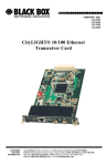
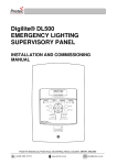
User manual
C-Box 7
Streetlight segment controller
In the set
C-Box 7
Current transformers
NOTE: The cable diameter and maximum
current according to current transformers
parameters.
GSM Antenna
C-Box 7
User manual
Door switch
Required
Cross-headed screwdriver
Flat-headed screwdriver
3mm
Drill
DIN rail
19mm
Wrench
Wires
22mm
0,2...2,5 mm2
0,75...1,5 mm2
C-Box 7
User manual
Safety and High Voltage Warning
Caution
Only qualified persons are allowed to install
and start up the Citylight products.
Inappropriate opening of the products is
prohibited.
Prior to installing and commissioning the
C-Box7, read these instructions carefully.
Please keep these instructions as you may
need them later.
C-Box 7
User manual
Safety and High Voltage Warning
Warning
Ensure that the AC power mains are turned OFF before removing the cover,
handling the wiring, or or any other work is carried out on C-Box 7.
DO NOT apply power to the device until you have checked all wiring connections
and you are instructed to apply power.
Observe all the applicable safety and accident prevention regulations.
C-Box 7
User manual
Inserting and removing the SIM card
1
2
Remove the front cover of the device
using a flat-headed screwdriver.
Insert the SIM card into the holder.
C-Box 7
User manual
NOTE: When inserting the SIM card,
ensure the correct direction!
NOTE: Make sure the SIM card is activated in
data transmission mode and that the PIN code
is removed.
3
Secure the SIM card into the holder by pressing
on it. Put on the front cover of the device and
press it to fix it in place.
NOTE: To remove the SIM card, press
it down.
Installing on the DIN
1
Open the fixing brackets of the C-Box 7
using flat-headed screwdriver.
2
Place the C-Box 7 on the DIN rail and
fasten it by closing the fixing brackets.
C-Box 7
User manual
Wiring
1
Connect the A phase cable to the C-Box 7 mains
input (230 VAC), to the relay switching (COM) and
voltage measuring inputs (Ua) according to the
symbols on the device.
COM
220V
A
Ua
C-Box 7
User manual
7 mm
Wiring
2
Connect the B and C phases to the voltage
measuring inputs on the C-Box 7. Make sure the
phases are connected according to the
symbols (Ub and Uc).
Ub
7 mm
Uc
B
C
C-Box 7
User manual
Wiring
3
Connect the neutral cable to the C-Box 7 mains
(230 VAC) and voltage measuring input (N).
220V
Un
C-Box 7
User manual
7 mm
Wiring
4
Connect the contactor signal input (A1) to the C-Box 7
relay outputs. Connect the contactor signal input (A2)
against the neutral cable.
R1
R2
R3
7 mm
A1
A2
A1
A2
NOTE: Connect the relays according to the
sequence that corresponds to the sequence
of phases.
C-Box 7
User manual
Installing of the current transformers
1
3
Remove the screw lock of the current
transformer.
Using a flat-headed screwdriver, press down the
upper jaws of the plug and insert the sensor
cable wires into the lower jaws. Fasten the wires
by releasing the upper jaws.
NOTE: Follow the sequence of phases
according to the symbols on the C-Box 7.
C-Box 7
User manual
2
Place two-wire cable wires into clamps of
current transformer. Fasten the clamps with
cross-headed screwdriver.
Installing of the current transformers
4
Insert the plug into the C-Box 7.
Ia Ib Ic In
5
Open the current transformer and place it
on the cable.
Close it and check if the current transformer has
been entirely closed and fully fixed.
NOTE: Sequentially connect the current transformers according to the sequence of the phases.
C-Box 7
User manual
Installation of the GSM antenna
1
Using a drill create a hole in the casing of the
streetlight cabinet.
2
3
C-Box 7
User manual
Insert the antenna and fasten it by tightening
the nut with the wrench.
Connect the antenna plug to the C-Box 7 and
fasten it.
Installation of the door switch
1
2
Fix the door sensor to the streetlight cabinet
wall and its doors, so that in an closed state the
distance between the sensors does not exceed
10 mm.
Using a flat-headed screwdriver, press down
the upper jaws of the plug and insert the sensor
cable wires into the lower jaws. Fasten the
wires by releasing the upper jaws.
3
Insert the plug into
the C-Box 7.
SW
C-Box 7
User manual
Installation of the light sensor
1
Fasten the light sensors to the wall or pole
using screws.
NOTE: Place light sensor so that
artificial lighting does not shed
light onto it.
2
Using a flat-headed screwdriver, press down
the upper jaws of the plug and insert the sensor
cable wires into the lower jaws. Fasten the
wires by releasing the upper jaws.
3
Insert the plug into
the C-BOX 7.
15V 4-20mA
C-Box 7
User manual
Device configuration
1
2
Apply power supply for the C-BOX 7 and press
and hold the RESET button for 5 seconds.
To set the operator APN send an SMS with the
following content :
S:2280:"<APN>"
Example:
S:2280:”internet.lmt.lv”
The device delivers a conformation reply SMS
3
To set the destination server IP address and
PORT send an SMS with the following content :
S:2200:"<IP>",<port>
Example:
S:2200:"212.70.166.178",5683
The device delivers a conformation reply SMS
“OK” or rejection reply SMS “ERROR”.
C-Box 7
User manual
LED indication
Status
C-Box registered, weak coverage.
C-Box registered, normal coverage.
C-Box registered, good coverage.
C-Box registration in progress.
Waiting for configuration SMS.
(After the long RESET.)
Failed registration in GSM network.
Registration in GPRS failed.
Cannot connect to server.
Failed registration in GSM network.
SIM card error or PIN required.
GSM module error.
C-Box 7
User manual
LED indication
Power
C-Box mains connected.
C-Box mains disconnected.
R1 R2 R3
Relay is in open position.
Relay is in closed position.
SW
Switch is in open position.
Switch is in closed position.
EXT
INT
Tx
Rx
External meter electricity consumption
counting with blinking interval 1 impulse.
Electricity consumption counting with
blinking interval 0.01 Wh.
Connection with outdoor luminaire
controllers is being created.
Connection is created and data exchange
with outdoor luminaire controllers is
activated.
C-Box 7
User manual
Teliko Ltd
Zemitana str. 2b, Riga, LV-1012, Latvia
Phone: +371 67620626, Fax: +371 67620653
E-mail: [email protected]
www.teliko.com