1
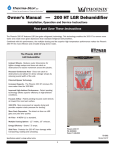
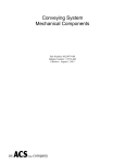
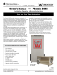
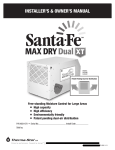
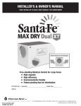
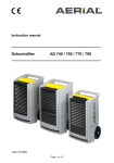
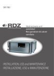
4201 Lien Rd.• Madison, WI 53704
Owner’s Manual — Phoenix 250 MAX
Installation, Operation & Service Instructions
Read and Save These Instructions
The Phoenix 250 MAX is the latest LGR dehumidifier in the Phoenix Stainless Series. This unit is a 145 ppd (@AHAM), 119 lb.
LGR with outstanding low grain and hi-temp performance. The unit pulls only 8.2 amps and has a powerful 365 CFM of airflow.
The 250 MAX combines the latest in Phoenix technology with a lineage dating back to the original Phoenix 200. The Phoenix
200, the first dehumidifier to be described as an LGR (Low Grain Refrigerant) dehumidifier, revolutionized the restoration
industry. Next Phoenix introduced the legendary 200 MAX, which has been a top seller for almost 2 decades, followed by
the addition of the Phoenix 200 HT featuring excellent high-temperature performance. With the 250 MAX, Phoenix has now
combined the best features of the 200 MAX and the 200 HT into one unit.
The Phoenix 250 MAX LGR,
High Capacity Dehumidifier
• High Capacity - Removes 145 pints per day at
AHAM
• 8.2 amps - Removes over 6.2 pints/kWh.
• R-410A Refrigerant
• More Grain Depression - Drier air from an LGR
finishes jobs quicker versus a conventional
refrigerant dehumidifier.
• Focused Airflow - Patented focused outlet directs
air downward across the wet surface.
• Motorized Impeller - 365 CFM; Faster drying and
superior static pressure for ducting.
• Multiple Ducting Options - 12” Inlet, 10” Outlet.
• Recessed 12” Wheels - Allows greater
maneuverability on the job site and efficient
storage. Rolls over obstacles with ease.
• MERV-11 Pleated Media Air Filter
Phoenix 250 MAX
4030010
TS-621
02/15
www.youtube.com/user/usephoenix
Specifications subject to change without notice.
Toll-Free 1-800-533-7533
www.UsePhoenix.com • [email protected]
1 Specifications
Table of Contents
Introduction.............................................................................. 1
1. Specifications................................................................... 2
2. Operation.......................................................................... 2
2.1 Transporting the Phoenix 250 MAX.......................... 2
2.2 Location...................................................................... 2
2.3 Electrical Requirements............................................. 3
2.4 Condensate Removal................................................. 3
2.5 Ducting........................................................................ 3
2.6 Power Switch.............................................................. 3
2.7 Pump Purge Switch.................................................... 3
2.8 Hour Meter.................................................................. 3
2.9 Defrost Control Adjustment....................................... 3
2.10 Low Pressure Control............................................... 3
3. Maintenance..................................................................... 4
3.1 Air Filter....................................................................... 4
3.2 Storage........................................................................ 4
4. Service............................................................................... 4
4.1 Warranty...................................................................... 4
4.2 Technical Description................................................. 4
4.3 Troubleshooting.......................................................... 5
4.4 Refrigerant Charging.................................................. 6
4.5 Air Mover Replacement.............................................. 6
4.6 Condensate Pump Replacement.............................. 6
4.7 Compressor/Capacitor Replacement....................... 6
4.8 Defrost Thermostat and Timer.................................. 6
4.9 Gravity Drain Option................................................... 6
4.10 Relay......................................................................... 6
5. Options and Accessories.................................................. 8
6. Wiring Diagram................................................................ 8
7. Service Parts List.............................................................. 9
Warranty..........................................................................10
Part No.4030010
110-120 VAC, 8.2 amps
Water
Removal
145 pints/day @ AHAM (80°F, 60%)
Refrigerant 2 lbs R410a
Charge
Blower
365 CFM
Internal Condensate Pump with 20 lift,
30’ vinyl hose
Operating Range
33°F to 105°F
Filters
16” x 20”
Standard 2” Pleated Media 65% MERV-11
Duct Options
Inlet – 12” Flex-Duct
Outlet – 10” Lay-Flat Warranty
Five years;
First year 100% of Parts and Labor
Second-fifth year 100% of Parts of sealed
refrigeration system.
Dimensions:
Dehumdifier
Width20”
Height 40”
Depth23”
Weight
119 lb
2 Operation
2.1 Transporting the Phoenix
The Phoenix 250 MAX must always be upright when
transported by vehicle. It may be tipped on to its handle and
back for loading and moving by hand.
Serial No. ___________________________
Purchase Date ______/______/_____
Dealer’s Name ___________________________________
2.2 Location
Note the following precautions when locating the Phoenix
250 MAX:
• It is designed to be used INDOORS ONLY.
• If used in a wet area, plug it into a GROUND FAULT
INTERRUPTER.
• DO NOT use the Phoenix 250 MAX as a bench or table.
•It must always be used in the upright position.
Read the operation and maintenance instructions
carefully before using this unit. Proper adherence to these
instructions is essential to obtain maximum benefit from
your Phoenix 250 MAX dehumidifier.
Toll-Free 1-800-533-7533
Power
2
www.UsePhoenix.com • [email protected]
• The air inlet on top & the side outlet must be at least
1 foot from walls and other obstructions to air flow.
• If the humid area is very large, dehumidification can
be improved by adding an outlet duct to circulate air to
stagnant areas (see Sec. 2.5).
2.3 Electrical Requirements
The Phoenix 250 MAX plugs into a common grounded outlet
on a 15 Amp circuit. It draws 8.2 Amps at 80°F,
60% RH. Amp draw increases with increasing temperature
and\or humidity. If used in a wet area, a ground fault
interrupter (GFI) is required.
If an extension cord is required, it must have a minimum of
14 gauge conductors if 25 feet long or less and 12 gauge
conductors if greater than 25 feet long.
2.4 Condensate Removal
2.8 Hour Meter
The digital hour meter measures the cumulative time that the
unit is turned on to tenths of an hour. It stores its total when
the unit is unplugged; the previous total will be displayed
when the unit is next turned on. It resets to zero after
99,999.9 hours of operation.
2.9 Defrost Control Adjustment
If the unit is going to run for more than 2 hours in an area
below 50°F, the defrost timer can be adjusted to improve
performance (see Sec. 2.9).When the Phoenix 250 MAX is
used in a cool area, or the dewpoint is below 50°, frost will
form on the cooling coil as it dehumidifies. When enough
frost forms, the defrost thermostat will initiate the timed
defrost cycle. The cycle periodically turns off the compressor
while allowing the blower to run. The frost is melted by the air
that the blower draws through the cooling coil.
The Phoenix 250 MAX is equipped with an internal
condensate pump to remove the water that is condensed
during dehumidification. This allows the condensate to be
pumped 30’ with the attached hose. If the condensate must
be pumped more than 20 feet above the unit, a second
pump must be added to relay the condensate. If the pump
fails and the unit must be used before it can be replaced, the
condensate can be drained by gravity (see Sec. 4.9).
DRYING TIP: Air’s ability to absorb moisture from wet
surroundings and the Phoenix 250 MAX’s ability to remove
moisture from that air is greatly improved at higher
temperatures. We recommend that the area to be dried be
heated to over 70°F if possible. Less drying time will be
required and efficiency will improve.
2.5 Ducting
If the low side refrigerant pressure drops to 35 PSIG, the
low pressure control opens and shuts off the compressor
and blower. It is an automatically reset control. Its primary
function is to prevent damage to the compressor if a leak
develops in the refrigeration system. It may also open if the
unit is A) used in a cool area (below 50°F) or B) stored where
it is below 40°F and then started. Under these conditions,
the unit will restart within several minutes; it may cycle
several times until the unit warms up.
A detachable rectangular exhaust collar is supplied that will
allow 10” round lay-flat duct to be attached to the Phoenix
250 MAX outlet. Lay-flat plastic ducting is available from
Therma-Stor.
To attach ducting to a collar, put the plastic duct end
through the collar center and roll the duct end outward so
that it overlaps the outside of the collar. The duct and collar
may then be quickly attached to the Phoenix 250 MAX by
snapping the collar over the four screws at the blower outlet.
2.10 Low Pressure Control
2.6 Power Switch
The power switch (right of hour meter) lights up when the unit
is turned on. The unit will continue to run in all conditions
until the switch is turned off; there is no dehumidistat.
2.7 Pump Purge Switch
This switch (left of hour meter) minimizes the water left
in the condensate pump reservoir for moving or storage.
Pressing and holding the pump purge switch will cause the
condensate pump to run. Hold the switch in until the flow
from the condensate hose stops.
Toll-Free 1-800-533-7533
www.UsePhoenix.com • [email protected]
3 Maintenance
4 Service
3.1 Air Filter
The Phoenix 250 MAX is equipped with a pleated fabric air
filter that must be checked regularly. The standard filter
is a MERV-11 high efficiency filter. Operating the unit with
a dirty filter will reduce the dehumidifier’s capacity and
efficiency and may cause the compressor to cycle off and on
unnecessarily on the defrost control.
CAUTION: Servicing the Phoenix 250 MAX with its high
pressure refrigerant system and high voltage circuitry
presents a health hazard which could result in death,
serious bodily injury, and/or property damage. Only
qualified service people should service this unit.
DO NOT operate the unit without the filter or with a less
effective filter as the heat exchange coils inside the unit
could become clogged and require disassembly to clean.
CAUTION: If the supply cord is damaged, it must be replaced
by the manufacturer, its service agent or similarly qualified
person in order to avoid a hazard.
3.2 Storage
4.1 Warranty
There are two issues to consider when the Phoenix 250 MAX
is stored between uses and both pertain to the water trapped
in the unit: damage caused by freezing or biological growth.
The effect of the trapped water can be greatly reduced if
precautions are taken to remove as much as possible before
storage.
1. Use the pump purge switch (see Sec. 2.7 & Fig. 4) to
reduce the water level in the reservoir.
2. Stretch the hose flat to drain it completely. Raise one end
above your head and spool hose while draining water out
the other end.
4.2 Technical Description
A warranty certificate has been enclosed with this unit;
read it before any repair is initiated. If a warranty repair is
required, call the factory first at 1-800-533-7533 for warranty
claim authorization and technical assistance.
The Phoenix 250 MAX uses a refrigeration system similar
to an air conditioner’s to remove heat and moisture from
incoming air, and to add heat to the air that is discharged
(see Fig. 2).
If the unit will not be exposed to freezing temperatures, an
alternative to reduce biological growth is to flush the unit
with a bio-fungicide that is approved for use with copper,
aluminum and polyethylene. To flush:
1. Run the hose to a drain.
2. Plug in the unit but do not turn it on.
3. Remove the air filter. Slowly pour a quart of the chemical
through the heat exchanger
4. Hold in the pump purge switch to reduce the water level
in the reservoir.
5. Flush with water.
Figure 2: Refrigeration system
Hot, high pressure refrigerant gas is routed from the
compressor to the condenser coil (see Figure 2). The
refrigerant is cooled and condensed by giving up its heat
to the air that is about to be discharged from the unit. The
refrigerant liquid then passes through a filter/drier and
capillary tubing which cause the refrigerant pressure and
temperature to drop. It next enters the evaporator coil where
it absorbs heat from the incoming air and evaporates.
Toll-Free 1-800-533-7533
4
www.UsePhoenix.com • [email protected]
The evaporator operates in a flooded condition, which means
that all the evaporator tubes contain liquid refrigerant during
normal operation. A flooded evaporator should maintain
constant pressure and temperature across the entire coil,
from inlet to outlet.
The mixture of gas and liquid refrigerant enter the
accumulator after leaving the evaporator coil. The
accumulator prevents any liquid refrigerant from reaching the
compressor. The compressor evacuates the cool refrigerant
gas from the accumulator and compresses it to a high
pressure and temperature to repeat the process.
4.3 Troubleshooting
No dehumidification, neither air mover or compressor run
and power switch does not light when ON.
1. Unit unplugged or no power to outlet.
2. Power switch defective.
3. Loose connection in internal wiring.
No dehumidification, neither air mover nor compressor run
with power switch ON & lit.
1. Low pressure control open.
2. Power switch defective.
3. Loose connection in internal wiring.
Some dehumidification, air mover runs continuously but
compressor only runs sporadically.
1. Unit is in defrost cycle.
2. Defrost thermostat defective.
3. Loose connection in compressor circuit.
4. Defective compressor overload.
5. Defective compressor.
6. Defective relay.
7. Low refrigerant charge.
No dehumidification, air mover runs but compressor does
not.
1. Bad connection in compressor circuit.
2. Pump safety switch closed
2. Defective compressor capacitor.
3. Defective compressor overload.
4. Defective compressor.
5. Defective relay.
6. Low refrigerant charge.
Toll-Free 1-800-533-7533
Air mover does not run. Compressor runs briefly but cycles
on & off.
1. Loose connection in air mover circuit.
2. Obstruction prevents impeller rotation.
3. Defective air mover.
Unit removes some water but not as much as expected.
1. Air temperature and/or humidity have dropped.
2. Humidity meter and/or thermometer used are out of
calibration.
3. Unit has entered defrost cycle.
4. Air filter dirty.
5. Defective defrost thermostat
6. Low refrigerant charge.
7. Air leak such as loose front cover.
8. Defective compressor.
9. Restrictive exhaust ducting.
10. Faulty defrost thermostat
Unit runs but does not pump water.
1. Hose kinked or plugged.
2. Pump motor or float switch defective.
3. Pump check valve plugged.
4. Bad connection in pump circuit.
5. Hose disconnected internally.
Unit pumps water automatically but not when purge switch
is pushed.
1. Bad connection in purge switch circuit.
2. Defective purge switch.
Evaporator coil frosted continuously, low dehumidifying
capacity.
1. Defrost thermostat loose or defective.
2. Defrost timer defective.
2. Low refrigerant charge.
3. Dirty air filter or air flow restricted.
Compressor runs with power switch OFF.
1. Defective relay.
2. Defective power switch.
www.UsePhoenix.com • [email protected]
formation on the evaporator coil, the thermostat opens. The
compressor is then cycled off and on by the defrost timer.
The blower will continue to run, causing air to flow through
the evaporator coil and melt the ice when the compressor is
off. When the air temperature and/or humidity increase, the
evaporator temperature will rise and the thermostat will close
to end the defrost cycle.
4.4 Refrigerant Charging
If the refrigerant charge is lost due to service or a leak, a
new charge must be accurately weighed in. If any of the
old charge is left in the system, it must be removed before
weighing in the new charge. Refer to the unit nameplate for
the correct charge weight and refrigerant type.
4.5 Air Mover Replacement
4.9 Gravity Drain Option
The impeller has a PSC motor and internal thermal overload
protection. If defective, the complete assembly must be
replaced.
1. Unplug the power cord.
2. Remove the front cover.
3. Remove five screws attaching impeller inlet ring.
4. Remove the four screws mounting impeller to underside
of base plate.
5. Disconnect the blower leads
6. Reassembling with the new impeller in reverse order
using the above procedure in reverse.
If the condensate pump fails and cannot be replaced
immediately, the Phoenix 250 MAX can be used by draining
by gravity.
1. Unplug the unit and remove the front cover.
2. Push the plastic plug on the right side (see Fig. 4) out
from inside the unit.
3. Locate the heavy vinyl hose that connects the drain pan
to the condensate pump. Pull the end out of the pump.
4. Remove tie wrap holding drain tube to suction line.
5. Push that end of the vinyl hose through the hole in the
right side.
6. Connect a garden hose and run it to a drain. Keep the
hose as flat to the floor as possible to avoid air pockets
that would hinder draining. Placing the unit on something
above the floor will also improve draining.
4.6 Condensate Pump Replacement
The internal condensate pump removes water that collects in
the reservoir.
To replace the condensate pump:
1. Unplug the unit
2. Remove the rear skidplate
3. Unplug the pump wires from the wire harness
4. Remove the condensate hose and the screw attaching
the pump bracket to the base
5. Replace the pump, hose, wiring, bolts, and cover in the
reverse order
4.10 Relay
The contacts of the single pole, single throw relay complete
the power circuit to the compressor. The contacts are closed
when power is provided to the relay coil via the control circuit.
The control circuit includes the power switch, low pressure
control, defrost thermostat and timer.
4.7 Compressor/Capacitor Replacement
This compressor is equipped with a two terminal external
overload, run capacitor, but no start capacitor.
4.8 Defrost Thermostat and Timer
The defrost thermostat is attached to the refrigerant suction
tube between the accumulator and compressor. If the low
side refrigerant temperature drops due to excessive frost
Toll-Free 1-800-533-7533
6
www.UsePhoenix.com • [email protected]
5 Options and Accessories
4021475
4024969
4024750
4024935
16” x 20” x 2” Pleated Media 65% MERV-11 (Standard)
16” x 20” x 2” MERV-8
12” x 25’ Intake Flex Duct
10” x 250’ Lay-flat Duct
6 Wiring Diagram
WHT-21
WHT-20
WHT
LOW PRESSURE
SWITCH
POWER SWITCH
BLK-8
1
1
ORG-12
ORG-11
2 3
BLK
VIO-15
BLK-16
WHT
LOW
PRESSURE
CONTROL
WHT-14
ORG-9
1
NC
0
RELAY
6
1
1
1
ORG
1
WHT
2
S
OVERLOAD
POWER
PURGE
LIGHT
TIMER
MOTOR
HOUR
METER
ORG
WHT
GRY
CONDENSATE
PUMP MOTOR
GRY-22
CONDENSATE PUMP
BLK
BLK-1
NO
C
FLOAT
SWITCH
BLK
WHT
PUMP
PURGE
SWITCH
PUMP
FLOAT
SWITCH
GRY
WHT
WHT
BLK-17
BRN-18
RELAY
CONTACTS
4
BLU PUMP
CONNECTOR
IMPELLER
BLK
SAFETY
SWITCH
NC
IMPELLER
CAPACITOR
WHT
RED-7
WHT-19
R
YEL
PUMP
BLK PUMP
WHT
5
RUN
CAPACITOR
WHT-6
TERMINAL
BLOCK
3
WHT
C
4
TIMER
SWITCH
VIO
WHT
2
COMPRESSOR
BLK-3
2
0
DEFROST
CONTROL
BLOWER
MOTOR
ORG
PURGE SWITCH
RELAY
COIL
YEL
MAIN
POWER
SWITCH
TERMINAL
BLOCK
DEFROST
CONTROL
WHT-23
PUMP
SAFETY
SWITCH
BLUE PUMP
WHT-13
HOUR METER
BLU
C
YEL-4
SWITCH
LIGHT
WHT-10
WHT
5
DEFROST TIMER
2
3
WHT-2
115VAC, 60HZ, 1PH
CAPACITOR
COMPRESSOR
WHT-5
BLK
CORD CORD
6
COMPRESSOR
OVERLOAD
RUN
S YEL CAPACITOR
C
COMPRESSOR
MOTOR
RED
WHT
WHT
R
GRY
WHT PUMP
PN 4035211
Toll-Free 1-800-533-7533
www.UsePhoenix.com • [email protected]
6 Service Parts
Item
Description
Qty
Part No.
17
18
19
20
21
22
23
24
25
26
27
28
29
30
31
32
1
Top Cover
1
4035206
2
Top Cover Hinge
2
4027267
3
Wheel 12” Gray
2
4026304
4
Cotter Pin 3/32”
1
1284404
5
Air Filter 1.75 x 15.5 x 19.5
1
4021475
6
Hose Plastic 0.56 ID x 24
1
4029894
7
Hose Plastic 0.38 ID
1
4021909
8
Hose Plastic 0.25ID x 33
1
4024916
9
Coupling Body 0.25 Tube
1
4024910
10
Coupling Insert 0.38 Tube
1
4023080
11
Capacitor Compressor 45mfd 370V 1
4033032-05
12
Capacitor Impeller 15mfd 370V 1
4033031-07
13
Thermostat (not shown)
1
4031376
14
Compressor
1
4029190
15
Hour Meter
1
4028795
16Cord
1 4032315
1
4039714
4034474-02
4028566
4034605-01
4026657
4034811
4028593
4029510
4035028
4026094
1177792
4025517
1223780
4035913
4021822
4021796
16
5
2
Overload Compressor (not shown)1
Evaporator Coil
1
Condenser Coil
1
Condensate Pump
1
Fan Motorized Impeller
1
Inlet Ring
1
Wire Duct Collar
1
Filter Drier (not shown)
1
Wire Harness (not shown)
1
Handle
1
Bolt M10-1.5 X 35
2
Washer M10 X 30
2
Hex Lock Nut M10-1.5
2
Skid Panel
1
Power Switch
1
Purge Switch
1
15,31,32
18
26,27,28,29
30
6
19
14
11
3,4
12
7,8,9,10
22
20
21
23
Specifications subject to change without notice.
Toll-Free 1-800-533-7533
8
www.UsePhoenix.com • [email protected]
Phoenix 250 MAX Dehumidifier Limited Warranty
Warrantor:
Therma-Stor LLC
4201 Lien Rd
Madison, WI 53704
1-800-533-7533
Who Is Covered: This warranty extends only to the original end-user of the Phoenix 250 MAX dehumidifier,
and may not be assigned or transferred.
First Year Warranty: Therma-Stor warrants that, for one (1) year the Phoenix 250 MAX dehumidifier will
operate free from any defects in materials and workmanship, or Therma-Stor will, at its option, repair or
replace the defective part(s), free of any charge.
Second Through Fifth Year Warranty: Therma-Stor further warrants that for a period of five (5) years,
the condenser, evaporator, and compressor of the Phoenix 250 MAX dehumidifier will operate free of
any defects in material or workmanship, or Therma-Stor, at its option, will repair or replace the defective
part(s), provided that all labor and transportation charges for the part(s) shall be borne by the end-user.
End-User Responsibilities: Warranty service must be performed by a Servicer authorized by Therma-Stor.
If the end-user is unable to locate or obtain warranty service from an authorized Servicer, he should call
Therma-Stor at the above number and ask for the Therma-Stor Service Department., which will then
arrange for covered warranty service. Warranty service will be performed during normal working hours.
The end-user must present proof of purchase (lease) upon request, by reasonable and reliable means.
The end-user is responsible for normal care. This warranty does not cover any defect, malfunction,
etc. resulting from misuse, abuse, lack of normal care, corrosion, freezing, tampering, modification,
unauthorized or improper repair or installation, accident, acts of nature or any other cause beyond
Therma-Stor’ reasonable control.
Limitations and Exclusions: If any Phoenix 250 MAX Dehumidifier part is repaired or replaced, the new
part shall be warranted for only the remainder of the original warranty period applicable thereto (but all
warranty periods will be extended by the period of time, if any, that the Phoenix 250 MAX Dehumidifier is
out of service while awaiting covered warranty service).
UPON THE EXPIRATION OF THE WRITTEN WARRANTY APPLICABLE TO THE Phoenix 250 MAX
DEHUMIDIFIER OR ANY PART THEREOF, ALL OTHER WARRANTIES IMPLIED BY LAW, INCLUDING
MERCHANTABILITY AND FITNESS FOR A PARTICULAR PURPOSE, SHALL ALSO EXPIRE. ALL WARRANTIES
MADE BY Therma-Stor ARE SET FORTH HEREIN, AND NO CLAIM MAY BE MADE AGAINST Therma-Stor
BASED ON ANY ORAL WARRANTY. IN NO EVENT SHALL Therma-Stor, IN CONNECTION WITH THE SALE,
INSTALLATION, USE, REPAIR OR REPLACEMENT OF ANY Phoenix 250 MAX DEHUMIDIFIER OR PART
THEREOF BE LIABLE UNDER ANY LEGAL THEORY FOR ANY SPECIAL, INDIRECT OR CONSEQUENTIAL
DAMAGES INCLUDING WITHOUT LIMITATION WATER DAMAGE (THE END-USER SHOULD TAKE
PRECAUTIONS AGAINST SAME), LOST PROFITS, DELAY, OR LOSS OF USE OR DAMAGE TO ANY REAL OR
PERSONAL PROPERTY.
Some states do not allow limitations on how long an implied warranty lasts, and some do not allow the
exclusion or limitation of incidental or consequential damages, so one or both of these limitation may not
apply to you.
Legal Rights: This warranty gives you specific legal rights, and you may also have other rights which vary
from state to state.
Toll-Free 1-800-533-7533
www.UsePhoenix.com • [email protected]