1
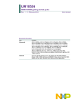
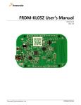
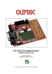
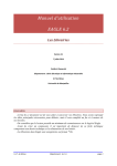
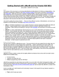
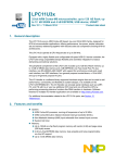
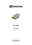
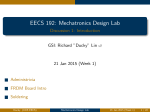
JTAG/SWD Converter Data Sheet
创建时间:2014/06/26 16:28
更新时间:2014/07/02 18:51
JTAG/SWD Converter
Version 1.5
Designed by
Allan K Liu
Ennovation LLC. , https://www.tindie.com/stores/allankliu/
JTAG/SWD Converter with Optional pogo-pins
Fig 1, PCB layout in EAGLE v5.11
Fig 2. Schematics in EAGLE v5.11
Feature
Designed for 10 pin JTAG/SWD layout used in popular ARM Cortex-M microcontrollers
Pitch converter between 100/50mil (2.54/1.27mm)
VCC/Vref connected by default, which can be cut off to prevent power contention.
Decoupling ready, unpopulated by default.
Optional 3/4/5 pogo-pins for firmware download.
M3 mouting holes for pogo-pins for debug purpose.
Small PCB area (2.54cm x 3.18cm) with bigger silkscreen.
Verified Platform
The converter has been verified on:
FRDM boards on KL25Z/KL05Z/MK20
LPCXpresso boards on LPC1114/LPC1227/LPC11UXX
CooCox CoLinkEx debugger
Segger J-Link debugger
PEmicro Multilink debugger
Keil ULink debugger
Warning
Don't use it in other different JTAG layout, such as AVR/8051/MIPS... unless you know what you are doing.
Consult the user manual of your JTAG probe to find out whether the VCC is Vsup or Vref.
Orientation
The connectors on board have no protective frames. So you have to find out PIN 1 of each connector and connect the
cable properly. PIN 1 has been marked with a triangle ▼or ▶.
SWD Pogo-pin
In final product, JTAG/SWD connectors will not be populated on board due to space restriction and cost issue.
Therefore, pogo-pin is very useful in small production phase. However, the developers will define their own layouts,
which make things confused.
We defined a protective layout to provent wrong direction.
Nr. Name
Default
1
SWD_DIO
High by internal pull high
2
GND
Low
3
SWD_CLK
Low by internal pull low
4
nRST
Low
5
VCC/Vsup/Vref
High
There are three configurations of SWD layout:
DIO + GND + CLK, which SWD uses RST command to reset micro
DIO + GND + CLK + nRST, which SWD uses hardware RST to micro
DIO + GND + CLK + nRST + VCC, which SWD can supply or monitor VCC and uses hardware RST
In the worst case, if the developer connect pogo-pin in reverse direction, GND connects to nRST, VCC connects to DIO.
It will not harm target micro since DIO is pulled high internally. At least, it will not be connected to GND instead.
Board Design for Pogo-pins
We use P50 pogo-pin, the diameter of pogo-pin is 0.5mm. You can design a SMT pad or through-hole pad with
smaller diameter, such as 0.35mm.
If you insist on using through-hole pad with bigger diameter, you can request us to switch from spear tip to other
pogo-pins with bigger tips with additional service charge.
Fig 3, pogo-pin with spear tip
Fig 4, pogo-pin with bigger tip.
Mouting Holes
Pressing pogo-pins in ISP mode is handy, but it can not support firmware debugging since you have to press it with
your hand.
We leave two M3 mounting holes on board, so you can use regular M3 screws to mount the pogo-pins against your
target board.
Known Limitations
There are two 5-pin SWD connectors on board. The right one is for 100mil pitch, the left one is for 50mil pitch. Due
to technology limitation of PCB maker, we can not support pogo-pins on 50mil pitch. So we use pin header for
50mil in current design.
A wrong silkscreen on the bottom layer. Which marks GND above "ENNOVATION LLC". That should be RST.
Requirement for Next Version
This is an open source developement tools when I develop my own project. You are welcome to ask questions, give
suggestions to me, which may makes it better. In fact, we have received some better ideas. We are considering:
Pitch converter for ARM/AVR/8051/MIPS/MSP430/CPLD/FPGA within 10 pin (3x2, 5x2, 3x1, 4x1, 5x1) with
generic structure.
Pogo-pins bridge within 10 pin (3x2, 5x2, 5x1) to support 50mil/100mil pitch in one board.
Pogo-pin sockets or jumper wires.
And yours?