1
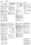
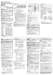
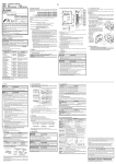
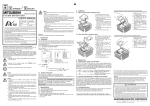
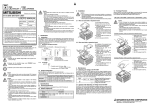
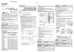
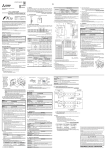
Side Side B A Side JAPANESE B JY997D48301C ENGLISH Requirement for Compliance with LVD directive STARTUP AND MAINTENANCE PRECAUTIONS FX3S SERIES PROGRAMMABLE CONTROLLERS HARDWARE MANUAL Certification of UL, cUL standards Turn off the power to the PLC before connecting or disconnecting any connection cable. Failure to do so may cause equipment failures or malfunctions. Turn off the power to the PLC before attaching or detaching the following devices. Failure to do so may cause equipment failures or malfunctions. - Peripheral devices, expansion boards, special adapters and memory cassette DISPOSAL PRECAUTIONS Manual Number JY997D48301 Revision C Date January 2014 Please contact a certified electronic waste disposal company for the environmentally safe recycling and disposal of your device. TRANSPORTATION AND STORAGE PRECAUTIONS This manual describes the part names, dimensions, mounting, cabling and specifications for the product. This manual is extracted from FX3S Series User's Manual - Hardware Edition. Refer to FX3S Series User's Manual - Hardware Edition for more details. Before use, read this manual and manuals of relevant products fully to acquire proficiency in the handling and operating the product. Make sure to learn all the product information, safety information, and precautions. And, store this manual in a safe place so that you can take it out and read it whenever necessary. Always forward it to the end user. Registration: Phillips is a registered trademark of Phillips Screw Company. The company name and the product name to be described in this manual are the registered trademarks or trademarks of each company. Effective January 2014 Specifications are subject to change without notice. 2013 Mitsubishi Electric Corporation Safety Precaution (Read these precautions before use.) This manual classifies the safety precautions into two categories: and Associated manuals Indicates that incorrect handling may cause hazardous conditions, resulting in death or severe injury. Indicates that incorrect handling may cause hazardous conditions, resulting in medium or slight personal injury or physical damage. may STARTUP AND MAINTENANCE PRECAUTIONS Do not touch any terminal while the PLC's power is on. Doing so may cause electric shock or malfunctions. Before cleaning or retightening terminals, cut off all phases of the power supply externally. Failure to do so may cause electric shock. Before modifying or disrupting the program in operation or running the PLC, carefully read through this manual and the associated manuals and ensure the safety of the operation. An operation error may damage the machinery or cause accidents. STARTUP AND MAINTENANCE PRECAUTIONS Turn off the power to the PLC before attaching or detaching the memory cassette. If the memory cassette is attached or detached while the PLC's power is on, the data in the memory may be destroyed, or the memory cassette may be damaged. Do not disassemble or modify the PLC. Doing so may cause fire, equipment failures, or malfunctions. For repair, contact your local Mitsubishi Electric representative. Compliance with EC directive (CE Marking) This document does not guarantee that a mechanical system including this product will comply with the following standards. Compliance to EMC directive and LVD directive of the entire mechanical system should be checked by the user/manufacturer. For more details please contact the local Mitsubishi Electric sales site. Requirement for Compliance with EMC directive The following products have shown compliance through direct testing (of the identified standards below) and design analysis (through the creation of a technical construction file) to the European Directive for Electromagnetic Compatibility (2004/108/EC) when used as directed by the appropriate documentation. Attention This product is designed for use in industrial applications. Note Manufactured by: Mitsubishi Electric Corporation 2-7-3 Marunouchi, Chiyoda-ku, Tokyo, 100-8310 Japan Manufactured at: Mitsubishi Electric Corporation Himeji Works 840 Chiyoda-machi, Himeji, Hyogo, 670-8677 Japan How to obtain manuals For the necessary product manuals or documents, consult with your local Mitsubishi Electric representative. Associated manuals FX3S Series PLC (main unit) comes with this document (hardware manual). For a detailed explanation of the FX3S Series hardware and information on instructions for PLC programming, refer to the relevant documents. Manual name . Depending on the circumstances, procedures indicated by also cause severe injury. It is important to follow all precautions for personal safety. The PLC is a precision instrument. During transportation, avoid impacts larger than those specified in section 2.1. Failure to do so may cause failures in the PLC. After transportation, verify the operations of the PLC. Please consult with Mitsubishi Electric for information on UL, cUL standard practices and the corresponding types of equipment. Manual No. Description FX3S Series User's Manual - Hardware Edition JY997D48601 MODEL CODE: 09R535 Explains FX3S Series PLC specification details for I/O, wiring, installation, and maintenance. FX3S/FX3G/FX3GC/ FX3U/FX3UC Series Programming Manual - Basic & Applied Instruction Edition JY997D16601 MODEL CODE: 09R517 Describes PLC programming for basic/applied instructions STL/ SFC programming and devices. MELSEC-Q/L/F Structured Programming Manual (Fundamentals) SH-080782 MODEL CODE: 13JW06 Programming methods, specifications, functions, etc. required to create structured programs. FXCPU Structured Programming Manual [Device & Common] JY997D26001 MODEL CODE: 09R925 Devices, parameters, etc. provided in structured projects of GX Works2. FXCPU Structured Programming Manual [Basic & Applied Instruction] JY997D34701 MODEL CODE: 09R926 Sequence instructions provided in structured projects of GX Works2. FXCPU Structured Programming Manual [Application Functions] JY997D34801 MODEL CODE: 09R927 Application functions provided in structured projects of GX Works2. FX Series User’s Manual - Data Communication Edition JY997D16901 MODEL CODE: 09R715 Explains N:N link, parallel link, computer link, no protocol communication by RS instructions/FX2N-232IF. FX3S/FX3G/FX3GC/ FX3U/FX3UC Series User's Manual - Analog Control Edition JY997D16701 MODEL CODE: 09R619 Describes specifications for analog control and programming methods for FX3S/FX3G/FX3GC/ FX3U/FX3UC Series PLC. FX3S/FX3G/FX3GC/ FX3U/FX3UC Series User's Manual - Positioning Control Edition JY997D16801 MODEL CODE: 09R620 Explains the specifications for positioning control of FX3S/FX3G/ FX3GC/FX3U/FX3UC Series and programming procedures. Authorized Representative in the European Community: Mitsubishi Electric Europe B.V. Gothaer Str. 8, 40880 Ratingen, Germany Type: Programmable Controller (Open Type Equipment) Models: MELSEC FX3S series, FX3G series, FX3U series manufactured from June 1st, 2005 FX3U-232ADP FX3U-485ADP FX3U-4DA-ADP FX3U-4AD-ADP FX3U-4AD-PT-ADP FX3U-4AD-TC-ADP FX3U-485ADP-MB from April 1st, 2007 FX3U-232ADP-MB from December 1st, 2007 FX3U-4AD-PTW-ADP FX3U-4AD-PNK-ADP from November 1st, 2008 FX3G-232-BD FX3G-422-BD FX3G-EEPROM-32L FX3G-485-BD FX3G-1DA-BD FX3G-2AD-BD FX3G-8AV-BD from June 1st, 2009 FX3U-3A-ADP from February 1st, 2012 FX3U-ENET-ADP from March 1st, 2013 FX3S-MR/ES FX3S-MT/ES FX3S-MT/ESS Where indicates: 10,14,20,30 FX3S-CNV-ADP FX3S-MT/DS from September 1st, 2013 FX3S-MR/DS FX3S-MT/DSS Where indicates: 10,14,20,30 FX3G-2EYT-BD FX3G-4EX-BD FX3G-485-BD-RJ Standard EN61131-2: 2007 Programmable controllers - Equipment requirements and tests The following products have shown compliance through direct testing (of the identified standards below) and design analysis (through the creation of a technical construction file) to the European Directive for Low Voltage (2006/95/ EC) when used as directed by the appropriate documentation. Type: Programmable Controller (Open Type Equipment) Models: MELSEC FX3S series manufactured from March 1st, 2013 FX3S-MR/ES FX3S-MT/ES FX3S-MT/ESS Where indicates: 10,14,20,30 from September 1st, 2013 FX3S-MR/DS Where indicates: 10,14,20,30 Standard Remark EN61131-2: 2007 Programmable controllers - Equipment requirements and tests The equipment has been assessed as a component for fitting in a suitable enclosure which meets the requirements of EN61131-2: 2007 Caution for compliance with EC Directive Installation in Enclosure Programmable logic controllers are open-type devices that must be installed and used within conductive control boxes. Please use the FX3S Series programmable logic controllers while installed in conductive shielded control boxes. Please secure the control box lid to the control box (for conduction). Installation within a control box greatly affects the safety of the system and aids in shielding noise from the programmable logic controller. Incorporated Items Check if the following product and items are included in the package: Included Items Product FX3S-10M FX3S-14M FX3S-20M FX3S-30M 1 unit Dust proof protection sheet 1 sheet Manuals [Japanese/English] 1 manual 1. Outline 1.1 Part names [3] [2] [4] [5] [1] [6] [7] Remark Compliance with all relevant aspects of the standard. EMI Radiated Emission Conducted Emission EMS Radiated electromagnetic field Fast transient burst Electrostatic discharge High-energy surge Voltage drops and interruptions Conducted RF Power frequency magnetic field [10] [9] No. [1] [8] Name Top cover [2] Terminal names [3] Terminal block covers [4] Input display LEDs (red) [5] Peripheral device connecting connector cover 2.1 Generic specifications [6] POW Green On while power is on the PLC. RUN Green On while the PLC is running. Red ERR Red Flashing when a program error occurs. Lights when a CPU error occurs. [7] Output display LEDs (red) [8] The year and month of production [9] Model name (abbreviation) [10] DIN rail mounting hooks Model name W: mm (inches) W1: mm (inches) Direct mounting hole pitches MASS (Weight): kg (lbs) FX3S-10M 60 (2.37”) 52 (2.05”) Approx. 0.30 (0.66 lbs) Approx. 0.22 (0.48 lbs) Approx. 0.22 (0.48 lbs) AC power type DC power type FX3S-14M 60 (2.37”) 52 (2.05”) Approx. 0.30 (0.66 lbs) FX3S-20M 75 (2.96”) 67 (2.64”) Approx. 0.40 (0.88 lbs) Approx. 0.30 (0.66 lbs) Approx. 0.45 (0.99 lbs) Approx. 0.35 (0.77 lbs) FX3S-30M 100 (3.94”) 92 (3.63”) Item [8] [2] [3] [4] [9] [5] [6] [7] [8] No. Name [1] Optional equipment connector [2] Power supply terminal, Input (X) terminals [3] Variable analog potentiometers Upper side: VR1, Lower side: VR2 [4] RUN/STOP switch [5] Peripheral device connecting connector (USB) [6] Peripheral device connecting connector (RS-422) [7] Service power supply terminal (AC power type only), Output (Y) terminals [8] Terminal cover [9] Optional equipment connecting screw holes Right side 0 to 55 °C (32 to 131 °F) when operating and -25 to 75 °C (-13 to 167 °F) when stored Ambient humidity 5 to 95 %RH (no condensation) when operating Vibration resistance*1 The label of authenticity is affixed to the right side of the product. Product without the label is not covered by the warranty. 1.2 External dimensions and weight 2-4.5 mounting holes 82 (3.23″) 90 (3.55″) 8 (0.32″) Mounting hole pitches 10 to 57 - 0.035 57 to 150 4.9 - 10 to 57 - 0.075 57 to 150 9.8 - When installed on DIN rail When installed directly Sweep Count for X, Y, Z: 10 times (80 min in each direction) As for installation of the special adapters and expansion boards, refer to the following manual. Refer to FX3S Series User's Manual - Hardware Edition. Noise resistance By noise simulator at noise voltage of 1,000 Vp-p, noise width of 1 s, rise time of 1 ns and period of 30 to 100 Hz Dielectric withstand voltage 1.5 kV AC for 1 min Insulation resistance 5 M or more by 500 V DC megger Grounding Class D grounding (grounding resistance: 100 or less) <Common grounding with a heavy electrical system is not allowed.>*3 Working atmosphere Free from corrosive or flammable gas and excessive conductive dusts Working altitude <2000 m*4 INSTALLATION PRECAUTIONS Use the product within the generic environment specifications described in section 2.1 of this manual. Never use the product in areas with excessive dust, oily smoke, conductive dusts, corrosive gas (salt air, Cl 2 , H 2 S, SO 2 or NO 2 ), flammable gas, vibration or impacts, or expose it to high temperature, condensation, or rain and wind. If the product is used in such conditions, electric shock, fire, malfunctions, deterioration or damage may occur. Do not touch the conductive parts of the product directly. Doing so may cause device failure or malfunctions. Install the product securely using a DIN rail or mounting screws. Install the product on a flat surface. If the mounting surface is rough, undue force will be applied to the PC board, thereby causing nonconformities. When drilling screw holes or wiring, make sure cutting or wire debris do not enter the ventilation slits. Failure to do so may cause fire, equipment failures or malfunctions. Be sure to remove the dust proof sheet from the PLC's ventilation port when installation work is completed. Failure to do so may cause fire, equipment failures or malfunctions. Connect the peripheral device cables securely to their designated connectors. Loose connections may cause malfunctions. Turn off the power to the PLC before attaching or detaching the following devices. Failure to do so may cause device failures or malfunctions. - Peripheral devices, expansion boards, special adapters and memory cassette When a dust proof sheet is supplied with units, keep the sheet applied to the ventilation slits during installation and wiring work. To prevent temperature rise, do not install the PLC on a floor, a ceiling or a vertical surface. Install it horizontally on a wall as shown in section 2.2. Keep a space of 50 mm (1.97”) or more between the unit main body and another device or structure (part A). Install the unit as far away as possible from high-voltage lines, high-voltage devices and power equipment. Make sure to cut off all phases of the power supply externally before attempting installation or wiring work. Failure to do so may cause electric shock or damage to the product. 75 (2.96"): AC power type 49 (1.93"): DC power type Half amplitude (mm) 147 m/s2 Acceleration, Action time: 11 ms, 3 times by halfsine pulse in each direction X, Y, and Z WIRING PRECAUTIONS W Acceleration (m/s2) Shock resistance*1 Unit: mm (inches) W1 (Mounting hole pitches) Frequency (Hz) 2. Installation (general specifications) Notes Label of authenticity Install the PLC in an environment conforming to the generic specifications (section 2.1), installation precautions and notes. Installation location in enclosure Ambient temperature Installation 35-mm-wide DIN rail or Direct (screw) mounting (M4×2) When the top covers are open [1] 2.2 Installation location Specification 500 V AC for 1 min A Between each terminals and ground terminal*2 *1 The criterion is shown in IEC61131-2. *2 Dielectric withstand voltage and insulation resistance are shown in the following table. Terminal Dielectric strength Insulation resistance Terminals of main units Between power supply terminal (AC power) and ground terminal Between power supply terminal (DC power) and ground terminal Between input terminal (24 V DC) and ground terminal Space in enclosure Special adapter can be connected on the left sides of the main unit. If you intend to add special adapter in the future, keep necessary spaces on the left sides. 1.5 kV AC for 1 min 500 V AC for 1 min Between output terminal (relay) and ground terminal 1.5 kV AC for 1 min Between output terminal (transistor) and ground terminal 500 V AC for 1 min A FX3S-CNV-ADP Name Operation status display LEDs FX3U-4AD-ADP No. A 2.2.1 FX3S Series main unit A A ≥ 50 mm (1.97") Affixing the dust proof sheet The dust proof sheet should be affixed to the ventilation port before beginning the installation and wiring work. Be sure to remove the dust proof sheet when the installation and wiring work is completed. For the affixing procedure, refer to the instructions on the dust proof sheet. 2.3 Procedures for installing to DIN rail The products can be installed on a DIN46277 rail [35 mm (1.38”) wide]. This section explains the installations of the main units. For the special adapters, refer to the following manual. Refer to FX3S Series User's Manual - Hardware Edition. 2.3.1 Installation 1) Push out all DIN rail mounting hooks (below fig. A). B 5 M or more by 500 V DC megger 1) Terminals of expansion boards, special adapters Between terminal of expansion board (except FX3G-4EX-BD and FX3G-2EYT-BD) and ground terminal A Not allowed Not allowed Between FX3G-4EX-BD input terminal (24 V DC) and ground terminal Between FX3G-2EYT-BD output terminal (transistor) and ground terminal A 1) 2) Fit the upper edge of the DIN rail mounting groove (right fig. B) onto the DIN rail. B 500 V AC for 1 min 5 M or more by 500 V DC megger Between terminal of special adapter and ground terminal For dielectric with stand voltage test and insulation resistance test of each product, refer to the following manual. Refer to FX3S Series User's Manual - Hardware Edition. *3 For common grounding, refer to section 3.3. *4 The PLC cannot be used at a pressure higher than the atmospheric pressure to avoid damage. 3) Lock the DIN rail mounting hooks (below fig. C) while pressing the PLC against the DIN rail. C 3) 2.4 Procedures for installing directly (with M4 screws) The product can be installed directly on the panel (with screws). This section explains the installation of the main units. For the special adapters, refer to the following manual. Refer to FX3S Series User's Manual - Hardware Edition. 2.4.1 Mounting hole pitches Refer to the External Dimensions (section 1.2) for the product's mounting hole pitch information. 2.4.2 Installation 1) Make mounting holes in the mounting surface referring to the external dimensions diagram. 2) Fit the main unit (A in the right figure) based on the holes, and secure it with M4 screws (B in the right figure). B A B 3. Power supply/input/output specifications and examples of external wiring For the details refer to the following manual. Refer to FX3S Series User's Manual - Hardware Edition. DESIGN PRECAUTIONS Make sure to have the following safety circuits outside of the PLC to ensure safe system operation even during external power supply problems or PLC failure. Otherwise, malfunctions may cause serious accidents. 1) Most importantly, have the following: an emergency stop circuit, a protection circuit, an interlock circuit for opposite movements (such as normal vs. reverse rotation), and an interlock circuit (to prevent damage to the equipment at the upper and lower positioning limits). 2) Note that when the PLC CPU detects an error, such as a watchdog timer error, during self-diagnosis, all outputs are turned off. Also, when an error that cannot be detected by the PLC CPU occurs in an input/ output control block, output control may be disabled. External circuits and mechanisms should be designed to ensure safe machinery operation in such a case. 3) If an overload of the 24 V DC service power supply occurs, the voltage automatically drops, inputs in the PLC are disabled, and all outputs are turned off. External circuits and mechanisms should be designed to ensure safe machinery operation in such a case. 4) Note that when an error occurs in a relay or transistor output device, the output could be held either on or off. For output signals that may lead to serious accidents, external circuits and mechanisms should be designed to ensure safe machinery operation in such a case. When two wires are connected to one terminal WIRING PRECAUTIONS Make sure to cut off all phases of the power supply externally before attempting installation or wiring work. Failure to do so may cause electric shock or damage to the product. WIRING PRECAUTIONS 3.1 Wiring Cable end treatment and tightening torque For the terminals of FX3S series PLC, M3 screws are used. The electric wire ends should be treated as shown below. Tighten the screws to a torque of 0.5 to 0.8 Nm. Do not tighten terminal screws with a torque outside the above-mentioned range. Failure to do so may cause equipment failures or malfunctions. When one wire is connected to one terminal φ3.2 (0.13") 6.2 mm (0.24") or less Do not bundle the control line together with or lay it close to the main circuit or power line. As a guideline, lay the control line at least 100 mm (3.94") or more away from the main circuit or power line. Noise may cause malfunctions. Install module so that excessive force will not be applied to peripheral device connectors. Failure to do so may result in wire damage/breakage or PLC failure. Terminal Solderless screw terminal Solderless terminal 100 to 240 V AC 6.3 mm (0.25") or more φ3.2 (0.13") Breaker Terminal Power on 6.3 mm (0.25") or more PL <Reference> Terminal Manufacturer J.S.T. Mfg. Co., Ltd. Type No. FV1.25-B3A Certification UL Listed Pressure Bonding Tool Main unit 3.2 Power supply specifications and example of external wiring N Even if the AC power supply causes an instantaneous power failure for less than 10 ms, the PLC can continue to operate. Even if the DC power supply causes an instantaneous power failure for less than 5 ms, the PLC can continue to operate. If a long-time power failure or an abnormal voltage drop occurs, the PLC stops, and output is turned off. When the power supply is restored, it will automatically restart (when the RUN input is on). Fuse Class D grounding MC For details, refer to the following manual. Refer to FX3S Series User's Manual - Hardware Edition. 3.2.1 MC Power supply specifications Item Supply voltage Specification AC power type 100 to 240 V AC Allowable supply voltage range 85 to 264 V AC 20.4 to 26.4 V DC Rated frequency 50/60 Hz Allowable instantaneous power failure time Operation can be continued upon occurrence of instantaneous power failure for 10 ms or less. Operation can be continued upon occurrence of instantaneous power failure for 5 ms or less. Power fuse 250 V 1 A 250 V 1.6 A Rush current 15 A max. 5 ms or less/100 V AC 28 A max. 5 ms or less/200 V AC 20 A max. 1 ms or less/24 V DC FX3S-10M 19 W 6W FX3S-14M Power consumption*1 FX3S-20M 19 W 6.5 W 20 W 7W 21 W 8.5 W FX3S-30M 24 V DC service power supply 400 mA DC power supply DC power type 24 V DC DC - AC Power supply for loads connected to PLC output terminals 3.2.3 Example of external wiring [DC power type] 24 V DC power is supplied to the main unit. 24 V DC Circuit protector Power on PL Main unit MC Emergency stop MC Fuse - Class D grounding *1 This item shows values when all 24 V DC service power supplies are used in the maximum configuration connectable to the main unit, and includes the input current (5 or 7 mA per point). (The DC power type main unit does not have a 24 V DC service power supply.) MC MC Terminal Power supply for loads connected to PLC output terminals <Reference> Terminal Manufacturer J.S.T. Mfg. Co., Ltd. Type No. FV1.25-B3A FV2-MS3 Certification UL Listed Pressure Bonding Tool YA-1 (JST) 3.3 Grounding Ground the PLC as stated below. Perform class D grounding. (Grounding resistance: 100 or less) Ground the PLC independently if possible. If it cannot be grounded independently, ground it jointly as shown below. PLC Notes MC L YA-1 (JST) MC Emergency stop φ3.2 (0.13") 6.2 mm (0.24") or less DESIGN PRECAUTIONS 6.2 mm (0.24") or less Notes Input/output wiring 50 to 100 m (164’1” to 328’1”) long will cause almost no problems of noise, but, generally, the wiring length should be less than 20 m (65’7”) to ensure the safety. Example of external wiring [AC power type] 100 to 240 V AC power is supplied to the main unit. Terminal screw 6.2 mm (0.24") or less Connect the power supply wiring to the dedicated terminals described in this manual. If an AC power supply is connected to a DC input/output terminal or DC power supply terminal, the PLC will burn out. Noise resistance may be lower when the L and N wires of an AC power supply are not wired correctly. Please wire using the correct polarity. Do not wire vacant terminals externally. Doing so may damage the product. Perform class D grounding (grounding resistance: 100 or less) to the grounding terminal on the main unit with a wire 2 mm2 or thicker. Do not use common grounding with heavy electrical systems (refer to section 3.3). When drilling screw holes or wiring, make sure cutting or wire debris does not enter the ventilation slits. Failure to do so may cause fire, equipment failures or malfunctions. Make sure to properly wire to the main unit in accordance with the following precautions. Failure to do so may cause electric shock, equipment failures, a shortcircuit, wire breakage, malfunctions, or damage to the product. - Make sure to properly wire to the main unit in accordance with the rated voltage, current, and frequency of each terminal. - The disposal size of the cable end should follow the dimensions described in the manual. - Tightening torque should follow the specifications in the manual. - Tighten the screws using a Phillips-head screwdriver No.2 (shaft diameter 6mm (0.24”) or less). Make sure that the screwdriver does not touch the partition part of the terminal block. 3.1.1 3.2.2 φ3.2 (0.13") Other equipment Independent grounding (Best condition) PLC Other equipment Shared grounding (Good condition) PLC Other equipment Common grounding (Not allowed) Use ground wires thicker than AWG14 (2 mm2). Position the grounding point as close to the PLC as possible to decrease the length of the ground wire. 3.4 Input specifications and external wiring 3.4.4 For details, refer to the following manual. Refer to FX3S Series User's Manual - Hardware Edition. As for the details of Instructions for connecting input devices, refer to the following manual. Refer to FX3S Series User's Manual - Hardware Edition. 3.4.1 Input specifications Item Number of input points 3.5 Relay output specifications and example of external wiring Specification FX3S-10M 6 points FX3S-14M 8 points FX3S-20M 12 points FX3S-30M 3.5.1 16 points Input form Sink/Source 24 V DC +10%, -10% DC power type 20.4 to 26.4 V DC X000 to X007 3.3 k X010 to X017 4.3 k Input signal current X000 to X007 7 mA/24 V DC X010 to X017 5 mA/24 V DC ON input sensitivity current X000 to X007 4.5 mA or more X010 to X017 3.5 mA or more OFF input sensitivity current 1.5 mA or less Input response time Approx. 10 ms Sink input Source input No-voltage contact input PNP open collector transistor Input operation display LED on panel lights when photocoupler is driven. Fuse 100 to 240 V AC FX3S-14MT 6 points FX3S-20MT 8 points FX3S-30MT 14 points 8 points FX3S-30MR 14 points Output form Output connecting type Fixed terminal block (M3 screw) External power supply Output form Relay External power supply 30 V DC or less 240 V AC or less*1 Resistance load 2 A/point*2 Inductive load 80 VA*3 Output connecting type 5 V DC, 2 mA (reference value) - OFFON ONOFF Max. load Transistor (Sink) FX3S-MT/SS Transistor (Source) 0.5 A/point*1 Inductive load 12 W/24 V DC*2 OFFON ONOFF 5 s or less/10 mA or more (5 to 24 V DC) Y002 to Y015 0.2 ms or less/200 mA or more (at 24 V DC) Output circuit insulation Photocoupler insulation Mechanical insulation Output operation display LED on panel lights when photocoupler is driven. Output operation display LED on panel lights when power is applied to relay coil. Life of relay output contact 0V As for the details of life of relay output contact, refer to the following manual. Refer to FX3S Series User's Manual - Hardware Edition. 3.6.2 24V 24V 3.5.3 1. External wiring of sink output type X000 X000 3-wire type sensor X001 Fuse 3-wire type sensor Fuse Fuse *1 *1 3.5.4 Load Fuse COM0 3.4.3 Examples of input wiring [DC power type] 1. Sink input type 2. Source input type S/S COM0 *2 Main unit 2. External wiring of source output type 24 V DC S/S Y000 Cautions in external wiring Load 24 V DC This manual confers no industrial property rights or any rights of any other kind, nor does it confer any patent licenses. Mitsubishi Electric Corporation cannot be held responsible for any problems involving industrial property rights which may occur as a result of using the contents noted in this manual. DC power supply Main unit As for the details of cautions in external wiring, refer to the following manual. Refer to FX3S Series User's Manual - Hardware Edition. Fuse *2 DC power supply +V0 X001 X000 3-wire type sensor X001 3.6.3 3-wire type sensor Warranty Mitsubishi will not be held liable for damage caused by factors found not to be the cause of Mitsubishi; opportunity loss or lost profits caused by faults in the Mitsubishi products; damage, secondary damage, accident compensation caused by special factors unpredictable by Mitsubishi; damages to products other than Mitsubishi products; and to other duties. For safe use Y000 Main unit X000 Partition External wiring of transistor output Y000 AC power supply Y1 COM1 As for the number of outputs per common terminal, refer to “Chapter 4 interpretation of partition” and the following manual. Refer to FX3S Series User’s Manual - Hardware Edition. 0V X001 Y0 COM0 As for the number of outputs per common terminal, refer to “Chapter 4 interpretation of partition” and the following manual. Refer to FX3S Series User's Manual - Hardware Edition. *2 The total of inductive loads per common terminal should be the following value. - 1 output point/common terminal: 12 W or less/24 V DC - 4 output points/common terminal: 19.2 W or less/24 V DC S/S Load 0V 24V *1 The total load current of resistance loads per common terminal should be the following value. - 1 output point/common terminal: 0.5 A or less - 4 output points/common terminal: 0.8 A or less S/S Example of relay output wiring Output terminal 1.5 V or less Y000, Y001 Approx. 10 ms 3.5.2 Example: FX3S-30MT/ES 0.1 mA or less/30 V DC Output circuit insulation Response time For details on the terminal block layout, refer to the following manual. Refer to FX3S Series User's Manual - Hardware Edition. Interpretation of partition The partition of the output terminals (see following figure) indicates the range of the output connected to the same common. 5 to 30 V DC Resistance load Open circuit leakage current Response time 4. Terminal block layouts Fixed terminal block (M3 screw) FX3S-MT/S ON voltage As for the number of outputs per common terminal, refer to “Chapter 4 interpretation of partition” and the following manual. Refer to FX3S Series User's Manual - Hardware Edition. *3 UL and cUL standards approved at 120 and 240 V AC. N 100 to 240 V AC Number of output points Specification 4 points 6 points *2 The total load current of resistance loads per common terminal should be the following value. - 1 output point/common terminal: 2 A or less - 4 output points/common terminal: 8 A or less Class D grounding N Item FX3S-10MT FX3S-20MR *1 250 V AC or less when the unit does not comply with CE, UL or cUL standards. 3.4.2 Examples of input wiring [AC power type] 1. Sink input type 2. Source input type L Transistor output specifications FX3S-14MR Open circuit leakage current No-voltage contact input NPN open collector transistor Class D grounding Specification Min. load Photocoupler insulation Fuse 3.6.1 4 points Max. load Input circuit insulation L For details, refer to the following manual. Refer to FX3S Series User's Manual - Hardware Edition. FX3S-10MR Number of output points AC power type Input signal form Relay output specifications Item Fixed terminal block (M3 screw) Input impedance 3.6 Transistor output specifications and example of external wiring For details, refer to the following manual. Refer to FX3S Series User's Manual - Hardware Edition. Input connecting type Input signal voltage Instructions for connecting input devices Cautions in external wiring As for the details of cautions in external wiring, refer to the following manual. Refer to FX3S Series User's Manual - Hardware Edition. This product has been manufactured as a general-purpose part for general industries, and has not been designed or manufactured to be incorporated in a device or system used in purposes related to human life. Before using the product for special purposes such as nuclear power, electric power, aerospace, medicine or passenger movement vehicles, consult with Mitsubishi Electric. This product has been manufactured under strict quality control. However when installing the product where major accidents or losses could occur if the product fails, install appropriate backup or failsafe functions in the system. *1 Class D grounding. *2 Do not connect the [] terminals with others, since they are not available. HEAD OFFICE : TOKYO BUILDING, 2-7-3 MARUNOUCHI, CHIYODA-KU, TOKYO 100-8310, JAPAN HIMEJI WORKS : 840, CHIYODA CHO, HIMEJI, JAPAN