1
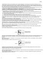
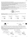
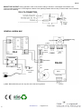
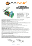
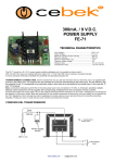
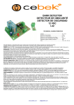
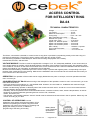
ACCESS CONTROL
FOR INTELLIGENT RING
DA-04
TECHNICAL CHARACTERISTICS
Voltage. ..................................... 12 V. S.C.
Low energy. ............................... 15 mA.
Maximum consumption. ............ 70 mA.
Timing relay. .............................. From 1 to 4 sec.
Max. applicable to the relay. ...... 3 A.
Duration min. pulse. ................... 40 msec.
Length max. pulse. ..................... 5 seconds.
Space min. between pulses. ...... 300 msec.
Space max. between pulses. ..... 2 seconds.
Space max. between pulses. ..... 2 seconds.
Max. melody. .............................. 10 beats + 9 spaces.
Time in self-lock status. ............... 5 minutes.
Measures. ........................ ........... 94 x 72 x 30 mm.
The DA-04, connected to a doorbell, to control access to any place or premises by reproducing exactly on the same ring of a
previously recorded song. The melody is kept in memory even after turn off the module.
Has self-locking repetition of failed attempts. Allows both recording and playback of the melody.
Includes leds, acoustic, and terminals.
VOLTAGE MODULE. The DA-04 must be supplied with a voltage of 12 V. S.C. adequately stabilized, so we recommend not
using simple feeders or rectifiers, which adversely affect the operation of the module, but a power supply. We suggest the EF-2,
or the model FE-103 which is well suited to the needs of the circuit. Install a fuse and a switch as illustrated. Both are essential to
protect the module for your own safety, as reflected in the CE standard.
Observe the General Wiring. Asked the layout of the source output, a positive and negative power, corresponding to the input
terminal of the module shown in the drawing. Make sure the installation was successful and do not activate the switch until you
have read the rest of the instructions.
OPERATION. The operation of the module can be roughly divided into two parts or concepts, control of operations and their
use in common job
CONSIDERATIONS OF DA-04. Before turning to the description of the operations control or use in common work, you must
follow these instructions:
- If the input wiring ring exceeds 50 cm., use shielded cable. However, do not exceed 2 m. installation and maximum length,
otherwise the circuit may operate incorrectly.
- Please note that during operation in different parts of the module can reach 230 V. circular C.A. so we recommend extreme
care and attention during assembly and handling.
- Ultimately, the DA-04 protection from inclement weather direct, excessive moisture, water, extreme temperatures, as well as
equipment or industrial parasites generating devices such as coils, contactors,
motors, fluorescent, etc.
- The switches 1 and 2 battery switches "Control" should never be selected at the same time in the On position. Select only one
of them according to your task
CONTROL OF OPERATIONS. Control
Operations were performed through the battery of four
switches incorporating the module. Using the Control
Operations can perform the functions of recording and
playing the melody of access, in addition to
programming of the timing of the relay.
www.cebek.com
Battery Status
Control Switches
Operations in
motherboard
-
[email protected]
DA-04
OPERATION. The DA-04 is an intelligent circuit, specially designed to control access to doors with an external ring. The
module, after being recorded a tune in memory, and then connecting it to the doorbell, you'll see every keystroke made on it.
If the pulses correspond to the reproduction of the prerecorded melody, the trigger circuit output, allowing the opening of the
door. If the pulses do not respond to the pattern of the melody, the circuit denied access.
The bell, when connected in parallel with the DA-04, every time you press will sound, masking and enhancing function of the
module. Only knowledge of it and the reproduction of the melody allow automatic opening of the door.
CONTROL OF OPERATIONS. RECORD OF THE MELODY. The recording of the melody is essential for module
operation. For reasons of subsequent recognition of the melody, the DA-04 is bounded at pulse specifications described in
the Specifications. The effective translation of all of them can be summarized the following points:
- 1. Make beats defined, neither too short nor too long. Note that if pulse is too fast, the circuit will be ignored. Also, must
respect the minimum space maximum between keystrokes, etc.
- 2 º. In the recording, use the insert button on the motherboard, suited for that role. While this is produce can not provide
any momentum through ring entries.
- 3 º. Perform several tests with simple melodies, (few clicks), before recording the final.
- 4 º. Avoid the use of tunes codes widely used in calls to doors, this will ensure further exclusive access.
Power supply module, the LED "Pwr" lights. Below and start recording, first place Switch 1 switches battery referenced as
"CONTROL" in the On position. Immediately after the LED is On light indicating the correct circuit availability for the
operation.
Then use the panel push button to enter the desired track. If it exceeds the maximum capacity of this, or any errors occur
before the end of the recording, the LED will also light Off.
To end the recording can wait for the module detects a blank space over 2 sec., When which the recording will automatically
be captured in memory and illuminating the LED On and Off. Also can stop recording
placing the switch 1 in OFF position, generating the same result and work out common mode (LED On and Off off).
From that moment on, the notes will be recorded the melody introduced.
After recording, if it is stopped automatically, you must set switch 1 in OFF position and wait for the leds On and Off to turn
off.
If you have a new recording, repeat the process. The new tune will erase the previous one, being this method
Replacement the only way to remove a melody.
If there is no pulse after placing the switch 1 in ON position, the module will not record anything and consequently either
delete the contents of memory.
If you make a sustained push above 5 seconds, the module will record a recording mistake.
Sample selection
Recording function
Control
CONTROL OF OPERATIONS. Playing the melody. In memory storage module is the last track recorded for playback position
the battery switch 2 switches "CONTROL" ON, LED Off automatically after giving proper lights circuit availability for the
operation.
After that, tap the button on the board. The circuit will play exactly the contents of memory, illuminating the LED On and Off
when the end of this.
Press the play button to repeat as many times as you want
Sample selection
Playback function
Control
OPERATION JOINT WORK MODE. As indicated previously, the DA-04 as the melody stored provide or deny access in
response to keystrokes made on the ring which was installed.
The DA-04 has 2 inputs for connecting in parallel to the ring
The entry of three terminals referenced in Example 230 V. Input Connection as only acknowledge its connection fed exclusively
with rings parallel to 230 VAC .
The two terminals referenced input as Input 3 to 24 V. Just admit your connection in parallel with rings fed exclusively with
voltages between 3 and 24 V. DC or AC .
2
www.cebek.com
-
[email protected]
DA-04
Must choose to install and tension ring as one of two entries.
Never connect the two inputs at the same time though the input voltages are different. Nor attach a ringtone to each entry.
The market to ignore this warning not only void the warranty of the module but also irreversibly damage the circuit.
To enable this feature make sure that switches 1 and 2 are in the Off position. The circuit will remain at rest, On and Off
LEDs off push forward to any input on the ring (or on the push plate in test mode).
If you enter the correct melody ring, the module will automatically generate a signal of acceptance by the buzzer, connected
to the output and illuminating the LED On while it remains connected.
If composing a different tune than that stored in memory or any error occurs, the module will generate a sign of denial and
momentarily illuminate the LED Off.
The circuit supports up to five consecutive access attempts failed. After these come in an auto-lock, preventing any operation
on the module in 5 minutes, or by default until you restart the power.
After a tune correct previous failed attempts are eliminated, preventing its accumulation. Likewise, after 5 minutes of selflocking or after restarting the module, the circuit will remove the previous failed attempts
return to its normal operating state.
Between attempts to access must wait for the Off ledsOn or are turned off. If the relay is connected, for example, the LED will
stay lit On, remaining in that state until the output is disconnected and denying
form any operation.
Sample selection
Working as Normal.
Control
TIMING RELAY. The DA-04 lets you choose between 1, 2, 3 or 4 seconds, the time at which the relay, after a successful
login, you must be connected.
Locate the switches 3 and 4 as the combination indicated in the following picture
Relay time setting
in 2 sec
Relay time setting
in 1 sec
Relay time setting
in 3 sec
Relay time setting
in 4 sec
Buzzer. If desired, you can cancel the sound from the buzzer. To do this, disengage, open the two pins of jumper JP1,
JP provided by removing the factory piece. If you later want to restore sound warning, rejoin JP1 contacts.
JP1 Closed
Open JP1
JP Room
Buzzer disabled
Buzzer enabled
OUTPUT CONNECTION. The output of the DA-04 is controlled by a relay device which allows any type of load does not
exceed 3 A. The relay has three output terminals. The normally open at rest (NA), the normally closed at rest (NC) and
Common
The operation of this mechanism is identical to a switch, shutting down and giving way to one of the two poles of power, or
opening and denying it to pass through. The two terminals of this switch pseudo NA and the Common
To perform the inverse function must be used and common terminals NC The following chart shows the typical connection for
a device operated at 12 V. S.C. and one operated at 230 V. C.A.
230V AC
12V DC
www.cebek.com
-
[email protected]
3
DA-04
ABOUT THE OUTPUT. During operation of the circuit, and according to its load, it could happen a fluctuation or an
incorrect output performance. If this happens, install a circuit sparking between the two relay contacts used in this connection,
as shown in the drawing.
GENERAL WIGRIN MAP
Ring
The feed line ring
(*) Note
Button
FE-2
3-24V DC/AC
Alimentation
Fuse
250 mA
230V AC
DA-04
Audible
Power supply
switch
Relay
230V AC.
Output relay
(*) Note. Remember that you can only use one of the two ring entries
4
www.cebek.com
-
[email protected]
common