1
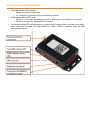
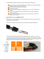
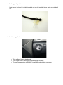
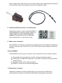
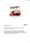
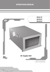
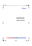
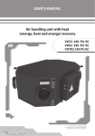
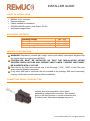
INSTALLER GUIDE PARTS OF INSTALLATION REMUC-2-AC controller External antenna Cables needed for installation GPS/GLONASS receiver (only Remuc PLUS) Illuminated usage button ELECTRICAL FEATURES Operating voltage Operating temperature Current consumption on stand-by Operating range of the heat sensor +9V...32V -30...+80C < 30mA (12V) -55...+125C IMPORTANT INFORMATION WARNING! Familiarize yourself with usage, service and safety instructions supplied with the device that is controlled using REMUC. CONTROLLER MUST BE INSTALLED SO THAT THE INSTALLATION NEVER EXCEEDS GIVEN VOLTAGE AND CURRENT INPUT LIMITS. CURRENT INPUT MUST BE GUARDED WITH A 5A FUSE PIN code for the SIM card must be one of the following: ”1234”, ”0000” or the PIN code query must be disabled completely If any other SIM card is used than the one included in the package, SIM card functionality must be verified with a mobile phone before installation. CONNECTING REMUC USAGE BUTTON Installer should proceed with caution when assembling usage button connector. Wire contact going in the plug must be in correct orientation and of correct color, otherwise breakage may occur. v1.1 © 2013 Embelin Ltd. , all rights reserved CONNECTOR SCHEMATICS Three different installation cables are available: RC2A RC2AE RC2AL Cable with full wiring Basic installation cable (Eberspächer) Basic installation cable (Webasto) 1 2 3 4 5 6 7 BLACK ORANGE NC NC GRAY GRAY GRAY Ground WBC x x x Button x x x x 8 VIOLET Input 2 9 RED Vin 10 YELLOW 11 WHITE 12 13 14 15 16 GREEN BROWN BROWN NC BLACK Output1 (+) (heater control) Output2 (+) (Fan control) Button Button Temp sensor Input 1 Ground RC2AL COLOUR FUNCTION RC2AE PIN NO RC2A Cable x x +0V...+24V (>1V = active) +0V...+24V (>1V = active) +12V…+24V (5A fuse needed) Output 0,5A (no fuse) Vin voltage (PIN 9) Output 0,5A (no fuse) Vin voltage (PIN 9) x x x x x x x x x x x x x INFORMATION x x x x RESETTING REMUC WITH USAGE BUTTON RESET / RESTART 1. Press and hold usage button at least 10 seconds. Release button. 2. Status light on usage button blinks for 10 seconds. After this controller is reset. 3. REMUC is ready for use when blinking stops. FACTORY RESET 1. Press and hold usage button for at least 10 seconds. Release button. 2. Status light on usage button blinks for 10 seconds. During this time press button shortly 3 times. 3. Controller will be reset to factory settings. 4. REMUC is ready for use when blinking stops. STATUS LIGHTS AND CONNECTIONS Controller status LED (orange) o Blinks: Controller is restarting o Lit: Controller is powered and connected to a network GSM modem status LED (red) o Blinks in 1 s intervals: Searching network or SIM card is not inserted or it’s locked. o Blinks in 3s intervals: Connected to a network If controller status LED does not switch to continuously lit mode after 5 minutes from restart, check SIM card PIN code. PIN code MUST be “1234”, “0000” or disabled. Wipe the SIM card contacts clean. INSTALLING REMUC 1. Insert SIM card in REMUC controller SIM card should be installed before mounting controller as the card slot might be hard to reach after mounting. Verify SIM card functionality before installation with mobile phone 2. Find a good installation spot for REMUC REMUC must be installed inside car, in a dry and protective place. Below dashboard on driver side is usually a good place. Install REMUC only on flat surfaces to avoid bending of the casing. 3. Find a good installation spot for the external antenna The install height of the antenna plays a great role in getting the best possible signal reception. Generally, the higher the antenna is, the better is the reception. Bottom edge of the windshield is a good example. Wipe the the install spot clean of any dirt, grease or stains before attaching the antenna. Finally, attach the antenna connector to the external antenna connector on the side of Remuc. Avoid following install spots with both external antenna and GPS receiver: Inside, on top of or under (closer than 2cm) a metallic structure. Metallic objects degrade the signal performance drastically. Under 20cm from persons inside the vehicle Outside of the vehicle In hot, cold and/or humid place. Allowed limits are -40 - +85C, <95% relative humidity On top of or in immediate vicinity of air bags or any other active or passive protective equipment In a place where it might prevent the correct use of the vehicle or block the visibility from the vehicle. 4. Install GPS receiver (only REMUC PLUS) GPS receiver must be installed in a location where there is a clear view of the sky. Car dashboard is a good example. Attach receiver cable connector to cable set connector according to the picture: If the delivered GPS receiver model doesn’t have the shown connector, you need to connect the wires manually into the 16-pin Remuc connector. Pay attention to the Wire contact orientation when inserting them into Remuc connector. Wire contact going in the plug must be in correct orientation, otherwise breakage may occur. PIN NBR COLOR 3 4 15 16 WHITE YELLOW RED BLACK 5. Connect installation cable Installation depends on the supplied cable set: When using Webasto cable (RC2AL), connect Webasto’s own controller cable directly to the Webasto connector on REMUC side. Operating voltage is supplied from this cable. REMUC installation cable has only heat sensor and connector for usage button. Eberspächer cable (RC2AE): PIN9 (red) supply voltage, PIN10 (yellow) to Eberspächer voltage control line, PIN1 (black) to ground. Full wiring cable (RC2A) is for general usage, see connector schematics. ATTENTION! When using full wiring cable with Webasto and OUT1/OUT2 are in use, you must connect Vin wire (red) to operating voltage! On systems with two or more batteries, always connect Remuc to the same battery as the fuel heater. 6. Find a good spot for heat sensor Heat sensor included in installation cable set can be installed either inside or outside of car. 7. Install usage button Drill an 8mm hole in dashboard Pull usage button cable from outside throught the hole Connect usage button to REMUC installation cable button connector Notice usage button cable wire color and crimp position when assembling the connector! Connector wire colors must match the wires in the installation cable. 8. Attach identification sticker in a visible place Identification sticker is used to identify REMUC in mobile application connection phase. Attach it to a place where it can be shot using phone camera. Good places are car’s A- or B-pillar, side of dashboard or on the lid of fuse box. 9. Make a test connection Once REMUC is connected, powered on and usage button is illuminated (not blinking), it is time to make the test connection. See the Quick Usage Guide included in the Remuc package. 10. Reset REMUC Finally REMUC must be reset to erase the test connection from the controller memory. Press and hold usage button for at least 10 seconds. Release button. Status light on usage button blinks for 10 seconds. During this time press button shortly 3 times. Controller will be reset to factory settings. REMUC is ready for use when blinking stops. 11. Releasing to customer Installation is ready for customer. Depending on the customer’s mobile phone, recommend the customer to familiarize him/herself to appropriate quick guide. CE-CERTIFICATION This device fulfills CE-certificate EN 50498 (2010) Embelin Ltd. declares that Remuc conforms directive 1999/5/EC relevant standards and regulations. Full Declaration of Conformity is in address http://www.embelin.fi/uploads/pdf/Remuc-DoC.pdf WEEE DIRECTIVE This symbol indicates that this product is not to be disposed of with your household waste, according to the WEEE Directive (2002/96/EC) and your national law. This product should be handed over to a designated collection point, e.g., on an authorized one-for-one basis when you buy a new similar product or to an authorized collection site for recycling waste electrical and electronic equipment (WEEE). USER MANUAL This user manual is prepared thoroughly. Constant product development may cause some information to end being out of date. Embelin Ltd. reserves the right to modify this user manual without any further notice. Embelin Ltd. disclaims any responsibility of any possible technical or delivery related errors, lack of information, random or direct damages caused by the quality or usage of this material. CHANGES Embelin Ltd. reserves all rights to modify product or user manual without any further notice. LIABILITY NOTICE Use of this product happens at your own risk. Embelin Ltd. will not guarantee fault free function, performance or any accuracy of the information displayed. Embelin Ltd. disclaims any responsibility to any property and/or personal damage caused by the use of this product. 1. REMUC controller has a two (2) year warranty 2. Warranty is valid from the date of purchase and requires that this card is filled out in full 3. Defects caused by material or manufacturing errors during warranty period will be handled either by replacing or fixing the faulty unit, as to Embelin Ltd. consideration. Warranty does not cover any refund claims, claims to reduce purchase price or any direct or indirect reclamations of damage. Warranty period is not extended in case of warranty service. 4. Any self-acting service or attempts to open the device voids the warranty. 5. If your device is in need of service covered by warranty, contact your retailer. If it is necessary to send the device to manufacturer for warranty service, make sure to include this warranty card (filled out in full) and a receipt of purchase. 6. Warranty does not cover any expenses caused by: • incorrect installation or usage, • overloading of the device, • damage caused by external force, • any damage that is a direct or indirect consequence of self-acting service attempt, opening or customizing of the device. • third party service that is not approved by Embelin Ltd. Vendor name and address / label Date of purchase Device serial number sticker