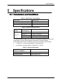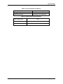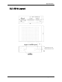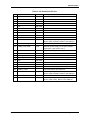
1
AB1A Driver User Manual D/N: AB1A458000-00 REV: F Nanomotion Ltd. POB 623, Yokneam 20692, Israel Tel: 972-73-2498000 Fax: 972-73-2498099 Web Site: www.nanomotion.com E-mail: [email protected] December 2011 Copyright This document contains proprietary information of Nanomotion Ltd., and Nanomotion Inc., and may not be reproduced in any form without prior written consent from Nanomotion Ltd. and Nanomotion Inc. No part of this document may be reproduced, translated, stored in a retrieval system or transmitted in any form and by any means, electronic, mechanical, photographic, photocopying, recording, or otherwise, without the written permission of Nanomotion Ltd. Information provided in this document is subject to change without notice and does not represent a commitment on the part of Nanomotion Ltd. Copyright June 2001, Yokneam, Israel. All rights reserved. All products and company names are trademarks or registered trademarks of their respective holders. Limited Warranty Nanomotion Ltd. (hereinafter NM) warrants the product (other than software) manufactured by it to be free from defects in material and workmanship for a period of time of one year (except those parts normally considered as consumable/expendable components such as motor conditioning brushes). The warranty commences thirty (30) days from the date of shipment. NM warrants those parts replaced under warranty for a period equal to the remaining warranty coverage of the original part. NM’s sole and exclusive obligation under this warranty provision shall be to repair, or at its sole option exchange defective products or the relevant part or component, but only if: (i) the Purchaser reports the defect to NM in writing and provides a description of the defective product and complete information about the manner of its discovery within ten (10) days of its discovery; (ii) NM has the opportunity to investigate the reported defect and determines that the defect arises from faulty material, parts or workmanship; and (iii) the Purchaser returns the affected product to a location designated by NM. These provisions constitute the exclusive remedy of the Purchaser for product defects or any other claim of liability in connection with the purchase or use of NM products. This warranty policy applies only to NM products purchased directly from NM or from an authorized NM distributor or representative. This warranty shall not apply to (i) products repaired or altered by anyone other than those authorized by NM; (ii) products subjected to negligence, accidents or damage by circumstances beyond NM control; (iii) product subjected to improper operation or maintenance (i.e. operation not in accordance with NM Installation Manuals and/or instructions) or for use other than the original purpose for which the product was designed to be used. NM shall not in any event have obligations or liabilities to the Purchaser or any other party for loss of profits, loss of use or incidental, increased cost of operation or delays in operation, special or consequential damages, whether based on contract, tort (including negligence), strict liability, or any other theory or form of action, even if NM has been advised of the possibility thereof, arising out of or in connection with the manufacture, sale, delivery, use, repair or performance of the NM products. Without limiting the generality of the preceding sentence, NM shall not be liable to the Purchaser for personal injury or property damages. Nanomotion Ltd. Page 2 of 29 CE Compliance CE Compliance This product has been tested for Electric Safety and Electromagnetic Compatibility and found to be in compliance with the following directives and standards: EMC Council Directive 89/336/EEC Safety Council Directive 73/23/EEC EN 55011:1998 + A1:1999 EN 61000-6-2:1999 EN 61010-1:1993 + A2:1995 Nanomotion Ltd. Page 3 of 29 Table of Contents Table of Contents 1 AB1A DESCRIPTION .................................................................................................. 8 1.1 General ........................................................................................................................ 8 1.2 Main Features .............................................................................................................. 8 1.3 Operating Principles ..................................................................................................... 9 2 CONNECTIONS AND I/O SETTINGS ........................................................................ 11 2.1 AB1A Front Panel ....................................................................................................... 11 2.1.1 Front Panel Connectors .............................................................................................. 11 2.1.2 Front Panel Indicators ................................................................................................ 12 2.2 Motion Controller/Joystick Connection ........................................................................ 12 2.2.1 Differential Analog Connection ................................................................................... 12 2.2.2 Joystick Connection.................................................................................................... 15 2.3 Cable Connections ..................................................................................................... 16 2.3.1 Shielding .................................................................................................................... 16 2.4 Motor Connections ..................................................................................................... 16 2.4.1 Motor Cable Length .................................................................................................... 16 2.5 Opto-isolated Inputs ................................................................................................... 17 2.5.1 Voltage Source Configuration ..................................................................................... 18 2.6 Fault Output................................................................................................................ 19 2.7 Before Operating the Motor ........................................................................................ 19 3 THERMAL ENVELOPE OF PERFORMANCE (EOP) ................................................ 20 3.1 Description ................................................................................................................. 20 3.2 Stage Heat Dissipation Consideration ........................................................................ 20 3.3 Thermal EOP for HR Motor Driven by AB1A, AB2, AB4 Drivers ................................. 21 4 AB1A OPERATION ................................................................................................... 23 4.1 Operation Modes ........................................................................................................ 23 4.1.1 Velocity Mode Operation ............................................................................................ 23 4.1.2 Step Mode operation .................................................................................................. 23 4.1.2.1 Enabling the Step Mode ............................................................................................. 23 4.1.3 Gate Mode Operation ................................................................................................. 23 4.1.3.1 Enabling the Gate Mode ............................................................................................. 24 4.2 Using the AB1A to Drive LS Motors ............................................................................ 24 5 SPECIFICATIONS ..................................................................................................... 25 5.1 Parameters and Conditions ........................................................................................ 25 5.2 AB1A Layout .............................................................................................................. 27 5.3 AB1A Pin Arrangement .............................................................................................. 28 Nanomotion Ltd. Page 4 of 29 List of Abbreviations List of Figures Figure 1: AB1A Block Diagram ......................................................................................... 9 Figure 2: Schematic Diagram of the Output Stage with an Internal LC Card ................... 10 Figure 3: AB1A Driver Box Front Panel........................................................................... 11 Figure 4: Differential Analog Input Connection ................................................................ 13 Figure 5: Non-Differential (single-ended) Analog Input Connection................................. 14 Figure 6: Joystick Connection ......................................................................................... 15 Figure 7: Opto-Isolated Input Interface ........................................................................... 17 Figure 8: Jumper 1 Configuration.................................................................................... 18 Figure 1: Motor Velocity vs. Command ........................................................................... 21 Figure 2: Motor Force vs. Velocity at the Various Work Regimes (a-g) ........................... 22 Figure 9: AB1A Layout .................................................................................................... 27 List of Tables Table 1: EOP Table for HR Motors Driven by AB1A, AB2, AB4 ...................................... 22 Table 1: AB1A Power Consumption................................................................................ 25 Table 2: Electrical Specifications .................................................................................... 25 Table 3: Physical dimensions ......................................................................................... 25 Table 4: Environmental Conditions ................................................................................. 26 Table 5: Analog Input Specifications ............................................................................... 26 Table 6: Control Terminal Pin Out................................................................................... 28 Table 7: Motor Output Port Pin Out ................................................................................. 28 Table 8: I/O Connector Pin Out ....................................................................................... 29 Nanomotion Ltd. Page 5 of 29 List of Figures List of Abbreviations A AC DC LC LED mA mW TTL Vrms Nanomotion Ltd. Ampere Alternating Current Direct Current Coil Capacitor Resonance Circuit Light Emitting Diode Milliampere Milliwatt Transistor-Transistor Logic Volts Root Mean Square Page 6 of 29 New Edition Remarks New Edition Notes: This edition is released to reflect the following changes: 1. New mode of operation has been added to the driver: Gate Mode (for more details see Section 4.1.3). This new feature is available in drivers bearing serial numbers 4800 and forward. 2. CE compliance section has been revised. Other changes to the manual are primarily editorials, aiming to make the manual a more user-friendly one. Nanomotion Ltd. Page 7 of 29 AB1A Description 1 AB1A Description 1.1 General The AB1A is a single-axis Amplifier Box designed to drive up to 32 motor elements in parallel. The AB1A Card consists of DC/DC converters that provide the voltages necessary to operate the amplifier circuit: +5V, ±12V, +3.3V. In addition, the card contains two LED indicators and the external interface connectors for the INPUT, MOTOR, and I/O signals. The system configuration may require an LC Card that is connected either internally to the AB1A Card, or externally in a separate LC Box. If the LC Card connection is external, then it is required to connect an adapter card to the AB1A. The adapter card shorts the necessary pins to enable the connection of the external LC Card. 1.2 Main Features High precision (11 bits) control of the power output stage Drives up to 32 Nanomotion motor elements in parallel Three modes of operation: Velocity Mode, Step Mode, and Gate Mode Interfaces with an Analog command Discrete inputs enable feedback from external sources, such as limit switches, emergency stop command, etc. LED indicators Reduced sensitivity to cable length and capacitance Compact dimensions Nanomotion Ltd. Page 8 of 29 AB1A Description 1.3 Operating Principles The AB1A Driver Box comprises the AB1A main card and an LC card. The AB1A Card converts the analog input command signal into a corresponding PWM square wave output signal that is fed to the LC Card. The LC Card produces the sine wave output voltage that drives the motor. The LC Card type and configuration depends on the number of motor elements driven. For 1 to 16 elements, the LC circuit is internal to the AB1A For 32 elements, the LC circuit is external to the AB1A (LC Box) An internal DC-to-DC converter that is fed from an external +48V power supply supplies the required DC voltages. Figure 1 illustrates a typical application of the AB1A Driver Box. Figure 1: AB1A Block Diagram The motor has three terminals: “UP” (red wire), “DOWN” (white wire) and “COMMON” (black wire). The voltage applied between the “UP” and the “COMMON” terminals causes the motor to move in one direction, while voltage applied between the “DOWN” and the “COMMON” terminals causes the motor to move in the opposite direction. Figure 2 is a schematic drawing of the power output. Nanomotion Ltd. Page 9 of 29 Operating Principles AB1A PWM - Square wave on the amplifier output +48v H-BRIDGE LC Card AC output that drives the motor "Common" "Phase" "Up" UP COMMON "Down" DIRECTION CONTROL DOWN NANOMOTION MOTOR Figure 2: Schematic Diagram of the Output Stage with an Internal LC Card Nanomotion Ltd. Page 10 of 29 Connections and I/O Settings 2 Connections and I/O Settings 2.1 AB1A Front Panel All AB1A connectors and indicators are located on the front panel. There are three connectors Control Terminal, I/O Port, and Motor Out, and two indicators. Figure 3: AB1A Driver Box Front Panel The detailed description of the AB1A connectors and indicators is given sections 2.1.1 and 2.1.2 below. 2.1.1 Front Panel Connectors Connector Description Control Terminal 5-pin connector that provides input from an external +48VDC power supply (6.5A max). Provides direct control of the motor ENABLE signal. See also Table 7 Motor Out D-type 9 pin connector male -Interfaces to the motor. See also Table 8. I/O Port D-type 25 pin connector female - Interfaces to the control source (joystick or controller See also Table 9. Nanomotion Ltd. Page 11 of 29 Connections and I/O Settings 2.1.2 Front Panel Indicators Condition VCC < 4.6V Motor Disconnected Motor Disabled Motor connected and enabled. Over-current Protection Alarm 1 Alarm 2 Off Off Orange Off Off Orange Green Off Red Red 2.2 Motion Controller/Joystick Connection The AB1A Driver can receive the input signals either from a motion controller or from a joystick. The schematic diagrams of the motion controller and joystick connections are provided in the following sections. NOTE: The motor may be operated with minimum control signals applied to the Control Terminal: +48V,GND POWER, +VIN, -VIN, ENABLE_IN. 2.2.1 Differential Analog Connection There are two options of connecting a motion controller to the AB1A Driver Box: Differential connection (see Figure 4) Single-Ended Connection (see Figure 5) The differential connection enhances noise immunity. Nanomotion Ltd. Page 12 of 29 Connections and I/O Settings Vin- Vin+ GND +48V AB1A ENABLE DC POWER SUPPLY 5 4 3 2 1 BLOCK TERMINAL MALE 2x LEDS MODE DC/DC Vout+ Twisted and shielded cable Vin+ 1 Vin- 14 VoutShield STATUS ENABLE FAULT 3 ENABLE 24 D-TYPE 25 PIN FEMALE CONTROLLER D-TYPE 25 PIN MALE GND 15 InMode 16 Amplifier Circuit PLANT Emergency Stop 12 Right Limit 22 Left Limit 10 GND 4 LC CIRCUIT D-Type 9-pin Male PHASE GND 5 GND 4 M.DIS DOWN 3 COM UP D-Type 9-pin Female 1 6 2 7 NANOMOTION Motor Figure 4: Differential Analog Input Connection Nanomotion Ltd. Page 13 of 29 Connections and I/O Settings Vin- Vin+ GND +48V AB1A ENABLE DC POWER SUPPLY 5 4 3 2 1 BLOCK TERMINAL MALE 2x LEDS MODE DC/DC Twisted and shielded cable Shield Vin+ 1 Vin- 14 GND 2 GND 9 STATUS ENABLE FAULT 3 ENABLE 24 Vout+ Vout- D-TYPE 25 PIN FEMALE CONTROLLER D-TYPE 25 PIN MALE GND 15 InMode 16 Amplifier Circuit PLANT Emergency Stop 12 Right Limit 22 Left Limit 10 GND 4 LC CIRCUIT D-Type 9-pin Male PHASE GND 5 GND 4 M.DIS DOWN 3 COM UP D-Type 9-pin Female 1 6 2 7 NANOMOTION Motor Figure 5: Non-Differential (single-ended) Analog Input Connection. Nanomotion Ltd. Page 14 of 29 Connections and I/O Settings 2.2.2 Joystick Connection Using the joystick for supplying the command voltage to the AB1A Driver Box allows the user to manually drive the motor without using a motion controller. 4 3 +48V Vin+ 5 2x LEDS GND Vin- AB1A ENABLE DC POWER SUPPLY 2 1 BLOCK TERMINAL MALE MODE Vout+ Shield Twisted and shielded cable +12V 23 Vin+ 1 -12V 11 GND 9 Vin- 14 GND 2 PLANT Status Fault DC/DC Amplifier Card D-TYPE 25 PIN FEMALE POTENSIOMETE R JOYSTICK 15 16 D-TYPE 25 PIN MALE GND InMode 3 Enable 24 Emergency Stop 12 Right Limit 22 Left Limit 10 4 Gnd LC CIRCUIT D-Type 9-pin Male GND 1 GND 5 PHASE 4 M.DIS 3 DOWN UP COM D-Type 9-pin Female 6 2 7 NANOMOTION MOTOR Figure 6: Joystick Connection Nanomotion Ltd. Page 15 of 29 Connections and I/O Settings 2.3 Cable Connections Connect the following groups of cables together, isolating each of the signals: POWER SUPPLIES – use 22 AWG (or lower AWG) wires for the power supplies. For noisy surroundings, it is recommended to twist the ground line and the power line together. ANALOG COMMAND – a twisted shielded cable is recommended. DISCRETE INPUTS – These signals are not sensitive to noise and can be grouped together in the same harness with any of the other groups. 2.3.1 Shielding Since the high motor voltage is induced on the cable shield, it is required to ground connection the shield on both sides. Both the driver and the motor should be grounded to the infrastructure earth. 2.4 Motor Connections The “Motor Connected” signal is available only at the motor connector, where it is shorted to ground. This ensures that unprotected motor pins will not be exposed to high voltage when the motor is not connected. If more than one motor is connected to the AB1A, use a suitable branch cable. If the motor type or the number of motor elements is changed, consult Nanomotion for the appropriate driver configuration changes that may be required. 2.4.1 Motor Cable Length The overall length of the cables that connect the AB1A Driver Box to the motor elements should be in accordance with the following: Up to 2 motor elements – 5m 4 – 32 motor elements – 10m NOTE: Use Nanomotion standard cables. Branching is possible to 2 and 4 identical motors. Branch cables must be of identical length, the sum of which not exceeding the allowed total cable length. Nanomotion can guarantee proper driver and motor performance only if Nanomotion standard cables are used. NOTE: Nanomotion Ltd. Page 16 of 29 Connections and I/O Settings 2.5 Opto-isolated Inputs The following inputs are opto-isolated and are activated by shorting them to ground (see also Table 9): Powering Up/Down Enable: Enables the driver activation. Should be activated before the motor is run Emergency Stop: Disables the AB1A output Mode Enabling Step Mode: Enables Step Mode operation Direction Restrictions Left Switch: Disables motor motion to the left Right Switch: Disables motor motion to the right VCC JP1 1 VCC User Voltage 390 To control logic Command Input AB1A Figure 7: Opto-Isolated Input Interface Nanomotion Ltd. Page 17 of 29 Connections and I/O Settings 2.5.1 Voltage Source Configuration The opto-isolated input signals are activated as short-to-ground. The voltage for the opto-isolated circuit (see Figure 7) is provided by either the internal +5V supply (default setting) or an external voltage supply via pin 20 on the I/O Port connector. The input to be activated should be shorted to external voltage supply ground. Configure jumper JP 1 (located near U1) on the AB1A card according to the voltage source: Pin 1 shorted to Pin 2, for an internal +5V source (factory setting) Pin 2 shorted to Pin 3, for an external voltage source ATTENTION: Do not short Pin 1 to Pin 3 on JP2. Doing so shorts the external power supply to the +5V supply! The input circuit is limited to sink up to 10 mA but not less than 3 mA. Internal voltage source External voltage source Figure 8: Jumper 1 Configuration Nanomotion Ltd. Page 18 of 29 Connections and I/O Settings 2.6 Fault Output Fault: An open collector logic output that is active (shorted to ground) under the following conditions: The motor is not connected and the “Motor Connected” signal is floating. Emergency Stop activated. NOTE: The Fault output is capable of sinking a maximum of 20 mA, and is not protected from over current. 2.7 Before Operating the Motor Before operating the Motor connected to the AB1A, verify the following: Card configuration (as specified on box) matches the motor to be operated. Jumper JP1 is set to the required mode of operation. All connectors are secured with screws. The external power supply is capable of supplying the required power consumption of the AB1A. There is no command when switching the power to “ON”. Make sure that all motors that are to be driven by the AB1A are correctly mounted avd preloaded. 1. The command should be limited according to the envelope of performance of the motor. Refer to the Motor User Manual. ATTENTION: 2. Driver should be grounded to infrastructure earth before operating. Nanomotion Ltd. Page 19 of 29 Thermal Envelope of Performance (EOP) 3 Thermal Envelope of Performance (EOP) 3.1 Description Motor operating temperature is a result of the balance between heat generation and heat dissipation. The heat generation depends on motor's work regime (driver command level). The heat is dissipated through the following heat transfer mechanisms: conduction, radiation and convection (the convection mechanism is negligible in vacuum environment). The heat dissipation mechanisms should be able to dissipate the heat generated in order to avoid overheating. The EOP gives the user the tools to assess the permitted operating conditions (for set ambient temperature and command, deriving the duty cycle and maximal continuous operation that assures safe operation). The user can either operate the motor for an extended period of time at a specific duty cycle or alternatively, can operate the motor for a continuous time period specified under “Maximal Continuous Operation Time” (see graph and table in section 3.3). After the continuous operation is completed, the driver must be disabled to cool down the motor for 400 sec in air and for 700 sec in vacuum environment. Notes: ◘ The duty cycle is the ratio of the operation time and the total work cycle (operation time + idle time). ◘ Upon operating a motion system in vacuum, it is expected that the Coefficient of Friction of the bearing structure will increase. This may require changing the system operation point on the thermal EOP curves. 3.2 Stage Heat Dissipation Consideration The motor heat dissipation mechanism is by convection and radiation to the motor case, and by conduction through motor’s ‘finger tips’. Hence, the motor and the Ceramic Driving Strip bases, must both be thermally designed to dissipate 2W each (per motor’s ‘finger tip’), with maximum temperature rise of 15C. Nanomotion Ltd. Page 20 of 29 Thermal Envelope of Performance (EOP) 3.3 Thermal EOP for HR Motor Driven by AB1A, AB2, AB4 Drivers Figure 9 illustrates motor velocity as a function of the applied driver command voltage. Allowing up to 30 mm/sec variations, use it as a reference and as a guideline for expected motor performance: 300 250 Velocity [mm/sec] 200 150 100 50 0 0 1 2 3 4 5 6 7 Command (V) 8 9 10 Figure 9: Motor Velocity vs. Command1 Figure 10 and Table 1 are designed to help the user determining the correct envelope of performance and avoid overheating and damaging the motor. 1 The motor operates horizontally at room temperature and low duty cycle (< 10%). It interfaces with the Ceramic Driving Strip (according to Nanomotion Specifications) and a cross-roller high quality slide. Nanomotion Ltd. Page 21 of 29 Thermal Envelope of Performance (EOP) Figure 10: Motor Force vs. Velocity at the Various Work Regimes (a-g) AB1A, AB2, AB4 Curve Air 25°C Air 50°C Vacuum Duty Cycle [%] Maximal Continuous Operation time [sec] Duty Cycle [%] Maximal Continuous Operation time [sec] Duty Cycle [%] Maximal Continuous Operation time [sec] a 100 ∞ 100 ∞ 100 ∞ b 100 ∞ 100 ∞ 44 184 c 100 ∞ 92 137 26 107 d 100 ∞ 62 93 17 72 e 78 87 47 70 13 55 f 56 62 33 50 9 39 g 50 56 30 45 8 35 Table 1: EOP Table for HR Motors Driven by AB1A, AB2, AB4 Nanomotion Ltd. Page 22 of 29 AB1A Operation 4 AB1A Operation 4.1 Operation Modes The AB1A can be operated in one of the following operation modes: Velocity Mode, in which the motor is driven continuously. Gate Mode, in which the motor is driven at low velocity by turning the driver output ON and OFF in time intervals defined by outside TTL signal in an open loop. Step Mode, in which the driver output is turned OFF and ON at predefined intervals, in order to drive the motor in discrete steps. 4.1.1 Velocity Mode Operation In this operation mode, the motor is driven continuously by applying the analog command voltage (± 10 V) using a relevant interface device (joystick or motion controller). 4.1.2 Step Mode operation In this operation mode the motor is turned on and off for fixed time intervals defined in the hardware as follows: ON phase - 1/16 second OFF phase - 0.5 second The amplitude of the output corresponds to the analog command input value and thus determines the speed of the motor. 4.1.2.1 Enabling the Step Mode Enable the Step operation mode, by shorting pin 16 (see Table 9) to the ground. 4.1.3 Gate Mode Operation In this operation mode, the motor is driven at low velocity in open loop by turning the driver output ON and OFF in time intervals defined by an outside TTL signal. The amplitude of the output corresponds to the analog command input value and thus determines the speed of the motor. In Gate Mode, as opposed to Step Mode the pulse width and pulse frequency are user-defined. The TTL allowable parameter values for the Gate Mode are as follows: Voltage - 2-5 Minimum pulse width - 50 µsec Maximum pulse frequency – 1 kHz Nanomotion Ltd. Page 23 of 29 AB1A Operation 4.1.3.1 Enabling the Gate Mode Enable the Gate mode of operation by shorting pin 21 (see Table 9) to the ground. Verify that pin 16 is not shorted to the ground at the same time. Once pin 21 is shorted, the driver is in Gate Mode. The TTL signal should now be conducted through pin 16. (See also section 4.1.2) 4.2 Using the AB1A to Drive LS Motors Under normal conditions, the LS series of motors should not be operated with command voltage exceeding 3.5V. To allow some margin in cases, which require momentarily use of higher power, the AB1A for the LS series of motors is limited to 5V. Nanomotion expects that during normal operation, the commanding controller should protect the motor, and assumes that in continuous operation the command will not exceed 3.5V. The protection scheme is as follows: the torque limit at the controller must be set to half of the maximum command voltage (5V), and be limited to 5 seconds. The controller RMS torque limit must be set to 35% of the full command. Nanomotion Ltd. Page 24 of 29 Specifications 5 Specifications 5.1 Parameters and Conditions Table 2: AB1A Power Consumption Power Input +48VDC ±5% Max Motor Output 250-290 Vrms Power Consumption without Load +48VDC/0.125A Power Consumption with Max load +48VDC/6.5A max Table 3: Electrical Specifications Supply Voltage +48v 5% Current Consumption Used When ≤ 200 mA 1x HR1 is connected. ≤ 500 mA 1x HR2 is connected. ≤ 800 mA 1x HR4 is connected. ≤ 1200 mA 1x HR8 is connected. The required power supply value should be calculated by adding the total power consumption of all the motors that are connected to the AB1A power consumption without motor (+48VDC/125 mArms) according to the following: I = 125mA + n*(current consumption of a single motor) n = Number of motors that are connected (n= 1/2/3/4). Table 4: Physical dimensions Nominal Mechanical Dimensions (WxDxH) 150x110x40 Weight 450 gr. Mounting options Desk top/Wall mount Nanomotion Ltd. Page 25 of 29 Specifications Table 5: Environmental Conditions Operating Temperature 0°C to 50°C Storage Temperature -40°C to 70°C Operating Humidity Up to 80%, non-condensing. Table 6: Analog Input Specifications Input voltage range: 10V Input impedance: 10k Input low pass filter: 4kHz Nanomotion Ltd. Page 26 of 29 Specifications 5.2 AB1A Layout 1 2 Figure 11: AB1A Layout Dimensions in mm General tolerance 0.4 Nanomotion Ltd. Page 27 of 29 Specifications 5.3 AB1A Pin Arrangement Table 7: Control Terminal Pin Out Pin Signal Name Function Description 1 +48V Input +48VDC Power Supply 2 GND Ground 3 VIN+ Input Analog Command from controller. 4 VIN- Input Analog Command from controller. 5 ENABLE_IN Input Enable. See section 0 Table 8: Motor Output Port Pin Out Pin Signal Name Function Description 1 GND Power supply ground Safety input; shorted to pin 6 in order to verify the motor connection and prevent the driver operation without the motor. 2 Motor_Phase High voltage output Used with an external LC Box Connected to the capacitor in the LC Box; otherwise not connected. 3 Motor_Up High voltage output Connected to the white motor terminal. 4 Motor_Common High voltage output Connected to the black motor terminal.. 5 Motor_Down High voltage output Connected to the red motor terminal. 6 Motor Connected Input Safety input; shorted to pin 1 in order to verify the motor connection and prevent the driver operation without the motor. 7 GND Power supply ground Shorted to the shield 8 Motor in High voltage output Used with an external LC Box connected to the AC switch circuit 9 N.C Not in use Optional Nanomotion Ltd. Page 28 of 29 Specifications Table 9: I/O Connector Pin Out Pin Signal Name Function Description 1 VIN+ Input Positive analog command input 2 GND 3 FAULT 4 GND 5 NC Not used 6 NC Not used 7 NC Not used 8 NC Not used 9 GND 10 LEFT_LIMIT Input Left Limit Switch. See section 0 11 -12V Output Accessory voltage for powering an external device. (Max 700mW). Return is the GND pin. 12 EMERGENCY_STOP Input Protection Input. See section 0 13 USER_VOLTAGE Input External power supply for the opto-isolated type inputs. (See section 2.5.1) 14 VIN- Input Negative analog command input 15 GND 16 STEP_IN Input Gate /Step Selection 17 RESET_IN Input Master Reset. Activated shorted to ground 18 NC Not used 19 NC Not used 20 NC Not used 21 GATE Input 22 RIGHT_LIMIT 23 +12V Output Accessory voltage for powering an external device. (Max 700mW). Return is the GND pin. 24 ENABLE_IN Input Enable. See section 0 25 +5V Output Accessory voltage for powering an external device. (Max 7.5W). Return is the GND pin. Nanomotion Ltd. Ground Output See section 2.6 Ground Ground Ground Gate mode enabling Left Limit Switch. See section 0 Page 29 of 29