1
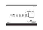
INSTRUCTIONS
Type OCS4-10
67022B 09/11 - (MBC)
• English
• Русский
• Portuguise
English
CS4 CENTRAL CONTROLLER
A central control unit with built-in wireless
transceiver for complete home heating management. Capable of controlling up to 16 rooms
in 5 different zones using OSD4 Thermostats
for underfloor heating and OSA4 Panel Heater
Controller for heating panels. Pre-programmed
for easy Plug & Go installation.
The central control unit features a built-in room
sensor and is supplied with a floor sensor
for controlling the floor heating in the room
concerned.
The unit is designed for flush mounting in a wall
socket. A baseplate for external wall mounting
is available.
TM
PRODUCT PROGRAMME
OCS4-10 Central Controller with build-in
room sensor, incl. floor sensor
WARNING – Important Safety Instructions
Disconnect the power supply before carrying
out any installation or maintenance work on this
unit and associated components. This unit and
associated components should only be installed
by a competent person (i.e. a qualified electrician). Electrical installation must be in accordance with appropriate statutory regulations.
MOUNTING OF SENSOR
The floor sensor contains a safety extra-low
voltage (SELV) circuit, allowing it to be placed
as close to the floor surface as possible without
having to take account of the risk of shock
should the sensor cable become damaged.
The two wires connecting the sensor to the
mounting box must be additionally insulated,
e.g. shrink flex.
To prevent loose wires in the fixed installation
from coming into contact with the terminal
block for the floor sensor, they must be restrained using cable ties.
It is recommended that the cable and sensor be
placed in a non-conductive installation pipe embedded in the floor (fig. 3). The end of the pipe
must be sealed and the pipe placed as high as
possible in the concrete layer. Alternatively, the
sensor can be embedded directly in the floor.
The sensor cable must be led through a separate pipe or segregated from power cables.
The floor sensor must be centred between
loops of heating cable.
The sensor cable may be extended up to 100
m by means of a separate two-core cable. Two
vacant wires in a multi-core cable used, for
GREEN COMFORT
Máximo conforto com reduzido consumo de energia
example, to supply current to the floor heating
cable must not be used. The switching peaks of
such current supply lines may create interference signals that prevent optimum controller
function. If a shielded cable is used, the shield
must not be connected to earth (PE). The twocore cable must be placed in a separate pipe or
segregated from power cables.
MOUNTING OF CENTRAL CONTROLLER
WITH BUILT-IN SENSOR
The room sensor is used for comfort temperature regulation in rooms. The Central Controller
should be mounted on the wall approx. 1.6 m
above the floor in such a way as to allow free air
circulation around it. The thermostat must never
be covered by a curtain or similar. Observe the
minimum distance from large metal surfaces,
electronic equipment, electric motors, etc.
(fig. 4a). To ensure good transmission, the unit
should be placed as high as possible, min. 50
cm above the floor (fig. 4b). Draughts and direct
sunlight or other heat sources must be avoided
(fig. 4).
Installing the central controller
1.Slide the power button down to Off “0”.
2.Release the front cover ONLY by inserting a
small screwdriver into the hole on either side
of the thermostat. (fig. 1)
3.Connect the wires in accordance with the
diagram (fig. 2).
4.Mount the thermostat in the wall socket.
5.Fit the frame and carefully press the cover
onto the thermostat. Ensure that both the
power slide button on the cover and the
power switch pin are down.
DO NOT open the controller by releasing the
four fixing clips on the back.
First time settings:
The first time the Central Controller is connected, push the power slide button to On “I”.
Language, time and date must be set using the
buttons. Let the central controller guide you
easily through:
- Language
- Time
- Date
- Zone selection
- Thermostat connection
PROGRAMMING
See user manual.
FAULT LOCATION
If the sensor is disconnected or short-circuited,
the heating system is switched off. The sensor
can be checked against the resistance table
(fig. 5).
CLASSIFICATION
The product is a Class II device (on front after
appropriate mounting in a flush box) and must
be connected in the following way:
Term. 1: Neutral (N)
Term. 2: Phase (L) 230 V ±10%, 50/60 Hz
Term. 3-4: Load, max. 16 A / 3600 W
Term. S: Fil Pilot input, 230 V
Term. 5-6: External floor sensor
ENVIRONMENT AND RECYCLING
Please help us to protect the environment by
disposing of the packaging in accordance with
national regulations for waste processing.
RECYCLING OF OBSOLETE APPLIANCES
Appliances with this label must not
be disposed of with general
household waste. They must be
collected separately and disposed
of in compliance with local
regulations.
TECHNICAL DATA
Voltage ......................... 230 V AC ±10% 50 Hz
Max. pre-fuse..............................................16 A
Output relay........... Make contact - SPST - NO
Output............................... Max. 16 A / 3600 W
Fil Pilot input.............................................230 V
Control principle................................... PWM/PI
Stand-by power.......................................... 1 W
RF frequency band........................... 868.3 Mhz
RF transmission range....100 metres/open field
Battery backup..................................... 5 years
Temperature range............................. +5/+40°C
Limit sensor ...................................... +5/+40°C
Ambient operating temperature......... +0/+25°C
Energy readout, accuracy............................ 2%
Sensor input type...................................... SELV
Pollution degree.............................................. 2
Overvoltage.............................................. Cat. II
Rated impulse voltage............................... 4 kV
Enclosure rating...................................... IP 21*
Dimensions.................... H/81, W/81, D/40 mm
Mounting depth..................................... 20 mm
Display. 100x64 pixel STN - white backlighting
EU Registered Design . ..... 001534462-0001/2
According to EN 60730-1:2009
Automatic action type 1
* IP 21 applies only to front with cover after
mounting in a flush box
The Central Controller is maintenance free.
OJ ELECTRONICS A/S
Stenager 13B · DK-6400 Sønderborg
Tel: +45 73 12 13 14 · Fax: +45 73 12 13 13
[email protected] · www.ojelectronics.com
ERROR CODES
E0:Internal error. The Central Controller must
be replaced.
E1: Built-in sensor short-circuited or disconnected.
E2: External sensor short-circuited or disconnected.
E5: Internal overheating. Inspect the installation.
E6: Communication error.
CE MARKING
According to the following directives:
LVD 2006/95/EC, EMC 2004/108/EC,
R&TTE 1999/5/EC.
© 2011 OJ Electronics A/S
1
Fig. 2
Fig. 2a
Fig. 4
Fig. 4a
© 2010 OJ Electronics A/S
Fig. 3
© 2010 OJ Electronics A/S
© 2010 OJ Electronics A/S
Fig. 1
Fig. 4b
Sensor
Temp.(˚C)
Value (ohm)
-10
64000
0
10
38000
23300
14800
20
30
4
The OJ trademark is a registered trademark belonging to OJ Electronics A/S · © 2011 OJ Electronics A/S
9700
BR929A08
Fig. 5