1
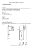
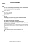
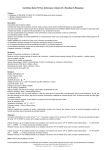
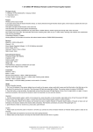
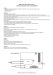
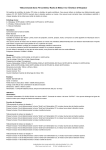
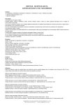
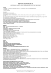
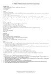
RF Wireless Remote Control Radio Controller / Transmitter & Receiver
Package Include:
1 x Receiver: S4C-DC06 / S4C-DC09 / S4C-DC12 / S4C-DC24 (4 Channel / Four Control Modes)
2 x Transmitter: C-4
1 x User manual
Feature:
Wireless control, easy to install
Control Lights, Motors, Fans, electrically operated Doors/Locks/Windows/Blinds/Cars or Other Appliances with AC110~240V or DC0~28V.
You can turn on/off the receiver with transmitter (remote control) from any place within a reliable distance; the wireless RF signal can pass
through walls, floors and doors.
With characteristics of reverse power protection and over current protection
Audible / visual indication
Use microcontroller model of EM78P156, an 8-bit microprocessor designed and developed with low-power and high-speed CMOS technology.
Reliable control: The transmitter (Encoding) and the receiver (Decoding) use an 8-bit code.
One/several transmitters can control one/several receivers simultaneously.
If you use two or more receivers in the same place, you can set them with different codes.
Transmitting Frequency: 315MHz / 433MHz
Receiver:
Model No.: S4C-DC06 / S4C-DC09 / S4C-DC12 / S4C-DC24
Channel: 4 CH
Control Modes: Latched, Momentary, Toggle, Momentary + Toggle
Coding Type: Fixed code
Coding Setting: By learning
Power Supply (Operating Voltage): DC6V (S4C-DC06), DC12V±1V (S4C-DC12), DC9V±1V (S4C-DC09), DC24V±1V (S4C-DC24)
Working Voltage Range of Relay: AC110~240V or DC0~28V
PCB size: 68mm x 48mm x 20mm
Case size: 75mm x 55mm x 30mm
Static Current: ≤6mA
Maximum Power: 5A / each channel
Transmitter:
Model No.: C-4
Channel: 4 CH
Remote Control Distance: 100m / 300ft (theoretically)
Encode: Fixed code by soldering
Unit size: 58mm x 39mm x 16mm
Power Supply: 1 x 23A -12V battery (included, can be used for 12 months)
Usage:
Setting different control modes (We have set the receiver as Toggle control mode before delivery. If you want to use other control modes, do as
following operation):
Setting control mode Latched: Disconnect Jumper-1 and Jumper-2.
Control mode Latched (Channel 1~4): Press -> On, other relays Off; Press other button -> Off.
Such as:
Press button 1: Turn on relay 1 (connect B and C, disconnect A and B)
Turn off other relays (disconnect B and C, connect A and B)
Press button 2: Turn on relay 2 (connect B and C, disconnect A and B)
Turn off other relays (disconnect B and C, connect A and B)
Setting control mode Momentary: Only connect Jumper-1.
Control mode Momentary (Channel 1~4): Press and hold -> On; Release -> Off.
Such as:
Press and hold button 1: Turn on relay 1 (connect B and C, disconnect A and B)
Release button 1: Turn off relay 1 (disconnect B and C, connect A and B)
Press and hold button 2: Turn on relay 2 (connect B and C, disconnect A and B)
Release button 2: Turn off relay 2 (disconnect B and C, connect A and B)
Setting control mode Toggle: Only connect Jumper-2.
Control mode Toggle (Channel 1~4): Press -> On; Press again -> Off.
Such as:
Press button 1: Turn on relay 1 (connect B and C, disconnect A and B)
Press button 1 again: Turn off relay 1 (disconnect B and C, connect A and B)
Press button 2: Turn on relay 2 (connect B and C, disconnect A and B)
Press button 2 again: Turn off relay 2 (disconnect B and C, connect A and B)
Setting control mode Momentary + Toggle: Connect Jumper-1 and Jumper-2.
SHENZHEN GUIYUAN INDUSTRY DEVELOPMENT CO.,LTD
Http://www.carymart.com E-Mail: [email protected]
Control mode Momentary (Channel 1, 2): Press and hold -> On; Release -> Off.
Press and hold button 1: Turn on relay 1 (connect B and C, disconnect A and B)
Release button 1: Turn off relay 1 (disconnect B and C, connect A and B)
Press and hold button 2: Turn on relay 2 (connect B and C, disconnect A and B)
Release button 2: Turn off relay 2 (disconnect B and C, connect A and B)
Control mode Toggle (Channel 3, 4): Press -> On; Press again -> Off.
Press button 3: Turn on relay 3 (connect B and C, disconnect A and B)
Press button 3 again: Turn off relay 3 (disconnect B and C, connect A and B)
Press button 4: Turn on relay 4 (connect B and C, disconnect A and B)
Press button 4 again: Turn off relay 4 (disconnect B and C, connect A and B)
We have learned remote control to the receiver. If you don’t want the receiver to work with the remote control, you can delete all codes of remote
controls, which are stored in the receiver.
Operation: Press and hold the button of receiver until signal LED flashes slowly; release the button, LED keeps slow flash. That means all stored
codes have been deleted successfully.
Learning the button of remote control:
1) Press the button of receiver; signal LED on the receiver keeps shining. The receiver enters into status of LEARNING.
2) Press any one button on remote control. If signal LED flashes quickly 15 times and turns off, it means learning is successful.
3) When receiver is in the status of LEARNING, press again the button of receiver, signal LED turns off, learning process will be discontinued.
4) The receiver can learn several remote controls with different codes.
Application Circuit
DC0~28V / AC110~240V
Lamp 4
Lamp 3
A
B
C
A
B
C
LED
C
Lamp 2
IC
B
Relay 4
Relay 3
A
Button
C
Lamp 1
B
Relay 1
Relay 2
A
Jumper-2
RF module
Jumper-1
Antenna
+
Power Supply_
A, B=Normally Closed; B, C=Normally Open.
Application: For DC12V motor or lamp
M
Motor 4
M
Motor 3
A
B
C
A
B
C
LED
M
C
Motor 2
IC
B
Relay 4
Relay 3
Button
A
M
C
Motor 1
B
Relay 1
Relay 2
A
_
+
_
Antenna
RF module
SHENZHEN GUIYUAN INDUSTRY DEVELOPMENT CO.,LTD
Http://www.carymart.com E-Mail: [email protected]
Jumper-2
Power Supply: DC12V
Jumper-1
+