1
FANTEC
MR-35DU3e
USER MANUAL
Menu
Menu ......................................................................................... 1
1. Product Introduction ........................................................... 2
2. Operation.............................................................................. 3
2.1 USB and eSATA Interface ............................................... 6
2.1.1 JBOD Modus ............................................................. 6
2.1.2 BIG Modus ................................................................ 7
2.1.3 RAID0 ........................................................................ 8
2.1.4 RAID1 ........................................................................ 9
2.1.5 Partitioning Volumes................................................ 10
3. Note..................................................................................... 14
4. Features.............................................................................. 15
4.1 USB 3.0 (5.0 Gbps) and eSATA (3.0 Gbps)................... 15
4.2 Serial ATA HDD ............................................................. 15
4.3. 4 Working Modes (BIG,JBOD,RAID0,RAID1) ............... 15
4.4 Supported Systems: ....................................................... 18
4.4.1 System Expansion for Windows Overview .............. 18
5. Package content ................................................................ 19
1
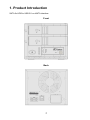
1. Product Introduction
SATA 2x HDD to USB 3.0 or eSATA interface.
Front
Back
2
2. Operation
The Hard Disk Installation: Sway from side to side the lock
, and pull the
doorknob to insert 1 or 2 hard disk. Close the doorknob and the installation will be
completed (The step will be represented in terms of following graphs)
Note: Sway from side to side the lock at the instructed point
which you could
open the doorknob to install/unload the hard disk. In contrast, when you sway from
side to side the lock at the instructed point
then you may not open it.
3
Connect to the computer host through USB, and turn on the power
Turn the switch to RAID0 and hold the reset switch for 3 sec, LED will keep bright and
the host will be entering the RAID0 active status.
Turn the switch to RAID1 and hold the reset switch for 3 sec, RAID1 LED keep bright,
and the host will be entering the RAID1 active status.
Turn the switch to JBOD and hold the reset switch for 3 sec, JBOD LED keep bright,
and the host will be entering the JBOD active status.
Turn the switch to BIG and hold the reset switch for 3 sec, BIG LED will keep bright,
the host will be entering the BIG active status.
Hard disk LED
sends blue light and has long-lasting bright light, which
indicates the hard disk connection is correct.
Hard disk LED
sends purple light and does not stop flashing, which
indicates the hard disk performing a Data transmission.
Hard disk LED
sends a constant purple light, which indicates a rebuild is
going on.
Hard disk LED
turns off, which indicates the hard disk is disconnected.
4
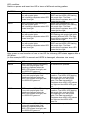
LED condition:
Switch on power and insert two HD in terms of different working pattern
PATTERN
HDD carries on the self-checking
RAID0
HDD1 and HDD2 LED flashing in
turn with purple lights.
Self- checking completes when LED
shows blue light
RAID1
JBOD
BIG
Data transmission
During Data transmission: The
HDD1 and the HDD2 LED flashing
with purple light. The Data
transmission completes when LED
shows the blue light
HDD1 and HDD2 LED flashing in
During Data transmission: The
turn with purple lights.
HDD1 and the HDD2 LED flashing
Self- checking completes when LED with purple light. The Data
shows blue light
transmission completes when LED
shows the blue light
HDD1 and HDD2 LED flashing in
During Data transmission:
turn with purple lights.
LED flashing with purple light while
Self- checking completes when LED operating different HDD. The Data
shows blue light
transmission completes when LED
shows the blue light
HDD1 and HDD2 LED flashing in
During Data transmission: The
turn with purple lights.
HDD1 and the HDD2 LED flashing
Self- checking completes when LED with purple light. The Data
shows blue light
transmission completes when LED
shows the blue light
After power on and insertion of one or two HD the following LED states appear after a
HD failure.
(In this example HDD1 is normal and HDD2 is damaged, otherwise vice versa)
PATTERN
HDD carries on the self-checking
Data transmission
RAID0
HDD1 and the HDD2 LED flashing
in turn with purple lights. Self
checking completes when the
HDD1 LED shows blue light, and
the HDD2 LED goes out.
HDD1 and the HDD2 LED flashing
in turn with purple lights. Self
checking completes when the
HDD1 LED shows blue light, and
the HDD2 LED goes out.
No transmission possible
RAID1
JBOD
HDD1 and the HDD2 LED flashing
in turn with purple lights. Self
checking completes when the
HDD1 LED shows blue light, and
the HDD2 LED goes out.
BIG
HDD1 and the HDD2 LED flashing
in turn with purple lights. Self
checking completes when the
HDD1 LED shows blue light, and
the HDD2 LED goes out.
5
Under the Data transmission
condition: The HDD1 LED flashing
with purple light, and the HDD2
LED flashing in turn with purple
lights. The Data transmission
completes when HDD1 LED shows
blue light and the HDD2 LED goes
out.
Under the Data transmission
condition: The HDD1 LED flashing
with purple light, and the HDD2
LED flashing in turn with purple
lights. The Data transmission
completes when HDD1 LED shows
blue light and the HDD2 LED
goes out.
No transmission possible
Attention:
1. If you use two HDD simultaneously and discover that the LED1 or LED2 flashing
with purple lights in turn for a long time. Please check and see if the HDD has installed
correctly.
2. If you simultaneously use two HDD, and the HDD damaged under RAID0,
JBOD, and BIG pattern, the data on the HDD will lose. Under the RAID1 pattern, you
may consider to take out the damaged HDD and replace formatted HDD instead.
2.1 USB and eSATA Interface
2.1.1 JBOD Modus
Insert the two disks in the HDD1 and HDD2 rack and connect the device with the
USB or eSATA & Power cable.
Turn on the power, switch the Mode to JBOD and press the Reset button for a few
seconds, the computer will automatically recognize the USB device and two new
drives should appear. If no new drive shows up, you have to initialize and/or format
the disks in the Disk Management (Attention, after formatting all data will be erased)
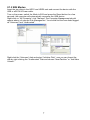
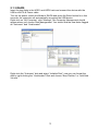
Right-click on “My Computer” click “Manage”, the Computer Management should
appear where you choose Disk Management. You should find two new disks flagged
as “Unknown” and/or “Unallocated”.
Right-click the “Unknown” disk and select “Initialize Disk”, now you can format the
disk by right-clicking the “Unallocated” Disk and choose “New Partition” or “Add New
Volume”.
6
2.1.2 BIG Modus
Insert the two disks in the HDD1 and HDD2 rack and connect the device with the
USB or eSATA & Power cable.
Turn on the power, switch the Mode to BIG and press the Reset button for a few
seconds, the computer will automatically recognize the USB device.
Right-click on “My Computer” click “Manage”, the Computer Management should
appear where you choose Disk Management. You should find the new disks flagged
as “Unknown” and “Unallocated”.
Right-click the “Unknown” disk and select “Initialize Disk”, now you can format the
disk by right-clicking the “Unallocated” Disk and choose “New Partition” or “Add New
Volume”.
7
2.1.3 RAID0
Insert the two disks in the HDD1 and HDD2 rack and connect the device with the
USB or eSATA & Power cable.
Turn on the power, switch the Mode to RAID0 and press the Reset button for a few
seconds, the computer will automatically recognize the USB device.
Right-click on “My Computer” click “Manage”, the Computer Management should
appear where you choose Disk Management. You should find the new disks flagged
as “Unknown” and “Unallocated”.
Right-click the “Unknown” disk and select “Initialize Disk”, now you can format the
disk by right-clicking the “Unallocated” Disk and choose “New Partition” or “Add New
Volume”.
8
2.1.4 RAID1
Insert the two disks in the HDD1 and HDD2 rack and connect the device with the
USB or eSATA & Power cable.
Turn on the power, switch the Mode to RAID1 and press the Reset button for a few
seconds, the computer will automatically recognize the USB device.
Right-click on “My Computer” click “Manage”, the Computer Management should
appear where you choose Disk Management. You should find only one new disks
flagged as “Unknown” and “Unallocated”.
Right-click the “Unknown” disk and select “Initialize Disk”, now you can format the
disk by right-clicking the “Unallocated” Disk and choose “New Partition” or “Add New
Volume”.
Note: When one of the hard disk is crashed, the new hard drive has to be
replaced while the device is running!
Turn the unit off and remove the faulty hard disk. At the next step turn on the
unit with the functional hard drive and wait for about 30 seconds.
Then insert the new hard drive into the bay from which you removed the faulty
drive. The recovery of the data will start automatically and is indicated by a
constant purple light on the front.
9
2.1.5 Partitioning Volumes
This section explains how to partition volumes after initializing them.
You must partition volumes for the host computer's operating system before you can
store data on the volumes.
Refer to the operating system's documentation for further guidance.
Partitioning a hard drive
MS Windows
Important: Before reconfiguring a volume, back up your data and delete previously
defined partitions. If no hard disk drives are connected to the device, the disks appear
as "Not Initialized" with no capacity allocated to it. Do not initialize or modify that
device.
1. Right-click the My Computer icon on your desktop and select Manage from the
pop-up window.
2. Select Disk Management under Storage to open the Windows Disk Manager.
10
Every disk should appear with the word “Basic”, a size value that shows the available
storage capacity, and a status of “Online”. Instead of Basic, a disk could appear
Unknown, Dynamic, or Not Initialized. A window opens with the selected disk (all
Unknown disks may appear in this window). Make sure the box next to each disk is
checked and click OK. The disk should now be marked as a Basic disk. If a disk
appears as “ Dynamic”, right-click the disk icon, and select Revert to Basic Disk.
Within a few seconds, the disk should be marked as a Basic disk. If a disk is marked
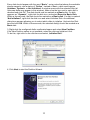
“Not Initialized”, right-click the disk icon and select Initialize Disk. An additional
dialog box appears allowing you to select which disks to initialize. Uncheck the Disk
item and click OK. Within a few seconds, the selected disk(s) should be marked as a
Basic disk.
3. Right-click the configured disk's unallocated space and select New Partition.
If the New Partition option is not available, select the disk and initialize it first.
To do this, right-click on the disk item and select „Initialize Disk".
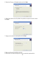
4. Click Next to start the Partition Wizard.
11
5. Select the Primary or Extended option and click Next.
6. Specify the partition size. By default, the partition occupies the entire volume.
Click Next.
7. Assign a drive letter or mount path and click Next.
8. Name and format the partition and click .
9. Review the file system settings and click to create the logical partition.
12
Mac OS X
Important: Before reconfiguring a volume, back up your data and drag the old drive to
the trash to un-mount previously defined partition. If no hard drives are connected to
the Storage Appliance, the Processor disk (8.0 GB Config Disk Media) will appear. Do
not remove or modify that partition. After you configure and partition the new volumes,
restore the backed-up data to the new configuration.
1. Launch Disk Utility from the Application > Utilities folder.
2. Select a configured disk and click the Partition tab. This procedure illustrates the
BIG Storage Policy configuration, which concatenates the capacity of all hard drives
connected to the device.
3. Select 1 Partition from the Volume Scheme drop-down list.
4. Enter a name for the volume in the Name field (such as “My BIG disk”.)
13
5. Select Mac OS Extended (journaled) from the Format drop-down list.
6. Specify the size of the partition in the Size field.
7. Click the Partition button.
8. Click Partition to acknowledge the warning.
Disk Utility mounts the created partition and represents it with an icon on the desktop.
The icon is labeled with the partition name.
3. Note
1. If this product is in use for the first time or the mode (BIG, JBOD, RAID0,
RAID1) is changed, we must initialize and format the HDD before. (All information will
be eliminated when format hard drives)
2. When you need to change different mode (BIG, JBOD, RAID0, RAID1) you must
press the RESET button, so that the enclosure can distinguish the exact mode.
3. If you require a faster data transfer, RAID0 MODE will be suggested to use.
4. If you require a higher data security, RAID1 MODE will be suggested to use.
5. If you require a bigger hard disk capacity, BIG MODE will be suggested to use
6. Connecting USB & eSATA simultaneously is impossible. eSATA connection will be
prioritized.
7. eSATA hostcontroller needs to support the port multiplier function in order to work
correctly with the JBOD mode.
8. If your eSATA host doesn’t support hot swap, please connect and power on the
case before you turning on the PC.
14
4. Features
4.1 USB 3.0 (5.0 Gbps) and eSATA (3.0 Gbps)
The FANTEC MR-35DU3e provides the following Serial Advanced Technology
Attachment (SATA) features:
Automatic negotiation between SATA I (1.5Gbps) and SATA II (3.0 Gbps)
Serial ATA 2.5 specification compliance (Gen2m)
Serial ATA Port Multiplier 1.1 specification compliance
For detailed information about SATA technology, refer to the following specifications
online:
Serial ATA: High Speed Serialized AT Attachment, Revision 1.0a
Serial ATA II: Extensions to Serial ATA 1.0a, Revision 1.1
Serial ATA II: Port Multiplier, Revision 1.1
The Serial ATA web site is http://www.serialata.org/.
USB Features
The FANTEC MR-35DU3e provides the following Universal Serial Bus(USB) features:
USB 1.0 and USB 2.0 specification compliance
For detailed information about USB technology, refer to the following specifications
online:
Universal Serial Bus Specification, Revision 1.1
Universal Serial Bus Specification, Revision 2.0
The USB Organization web site is http://www.usb.org/
4.2 Serial ATA HDD
Populated with two Serial ATA (SATA) hard disk drives (HDDs), each unit can
manage as much as 4,000 gigabytes (i.e., 4 terabytes) of data, depending on the
capacity of the hard disk drives that are installed. By combining multiple units in a
daisy-chained hierarchy structure, you can increase the total storage capacity of your
system.
4.3. 4 Working Modes (BIG,JBOD,RAID0,RAID1)
You can configure the FANTEC MR-35DU3e to use any of the following Storage
Policies to map the appliance's physical hard drives to virtual drives that are visible to
the host computer. The virtual drives are called volumes in the GUI. The host
operating system treats each volume as if it were a single physical drive.
This virtualization allows you to overcome restrictions that are imposed by physical
hard drives, such as speed, storage capacity or data storage reliability
15
BIG
The BIG storage policy concatenates a series of physical hard drives as a single large
volume; resulting in a seamless expansion of virtual volumes beyond the physical
limitations of singularly connected hard drives. BIG storage policy delivers maximum
storage space without a single large capacity and costly hard drive.
Hard drive A and B are concatenated into a single virtual volume in the Figure below
with a storage capacity that is equal to the sum of each of the physical hard drives A
and B.
It is also possible to create a BIG volume using only a single hard disk drive
connected to Port 0, and then increase the storage capacity of the volume later by
adding another hard disk drive to Port 1 and pressing the Mode Change pushbutton.
The new disk blocks of Port 1 will be concatenated to the end of the disk blocks of
Port 0, and any data that is stored on the existing BIG volume will be preserved.
However, it is not possible to expand an existing BIG volume by adding another hard
disk drive to Port 0 and still preserve any existing data on that volume.
JBOD
The JBOD (Just a Bunch of Disks) storage policy enables each hard drive to be seen
separately as one drive. JBOD storage policy is for a standalone (non-cascaded)
Storage Processor or the top-level node of a cascaded configuration, but not for
subordinate nodes. In a JBOD configuration, each physical drive is directly exposed.
16
RAID0
The RAID0 storage policy distributes access across all hard disks, also called
striping. RAID0 presents the best data speed but no data redundancy. RAID0 storage
policy accelerates hard disk operating speed by using many disks in parallel. Hard
drive data segments are written to different disks simultaneously which increases
performance while sacrificing data redundancy. To implement the RAID0 storage
policy, the device creates a single virtual volume that is striped across both hard
drives, with a storage capacity that is equal to the sum of both hard disk drives.
RAID1
The RAID1 storage policy stores all data in duplicate on separate drives to protect
against data loss due to drive failure. One drive mirrors the other at all times.
Every write operation goes to both drives. RAID1 provides the highest level of data
protection for critical data that you cannot afford to lose if a hard drive fails, but halves
the amount of storage capacity because all data must be stored twice. The resulting
storage capacity of the virtual RAID1 volume will be equivalent to the size of one hard
drive (if both drives are the same) or the smaller of the two drives (if they are
different). If one drive fails, the RAID1 volume is still usable, but it is in a vulnerable
state because its mirrored hard drive is inaccessible. When the offline drive comes
back online, the appliance begins a rebuild process immediately to restore data
redundancy. Although the volume remains available during the rebuild process, the
volume is susceptible to data loss through damage to the remaining drive until
redundancy is restored at the end of the rebuild and verification process. Host access
takes precedence over the rebuild process. If you continue to use the SAFE volume
during the rebuild, the rebuild process will take a longer time to complete, and the
host data transfer performance will also be affected.
17
4.4 Supported Systems:
Windows 2000/XP/VISTA/7 and MAC OS 9.0 and higher
4.4.1 System Expansion for Windows Overview
This appendix describes the procedures needed with Microsoft Windows for
expanding file systems that have been created on volumes that have increased in
size, while preserving all of your existing data. After you have added more hard disk
drives to increase the storage capacity of a BIG volume, you must use the
supplemental procedure described below to allow the expanded capacity to be
recognized by the Windows file system. A command-line utility named "Diskpart.exe"
("Disk Partition") enables you to manage hard disk partitions and volumes. This utility
is included as part of Windows XP Professional Edition, Windows 2003 Server and
Windows Vista. For Windows 2000 or Windows XP Home Edition, you must
download the "disk part" utility from Microsoft's website.
Additional third-party products (such as Norton Partition Magic) are available to
perform similar volume management activities, but those products are very
sophisticated and are not included in this manual.
Procedure
Before you can use DiskPart.exe commands on a hard drive disk partition/volume,
you must first list and then select the partition/volume to extend.
1. Open a command prompt window by clicking Start --Run, then entering "cmd"
2. At the command prompt, type “diskpart”.
3. Type ”list volume” to display the existing volumes on the computer.
18
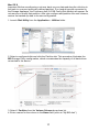
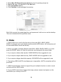
4. Type “select volume <volume_number>” where “<volume_number>” is the number
of the volume that you want to extend. In this case that will be “2”.
5. Type “extend”
6. Type “exit” to quit Diskpart.exe
The volume size will be updated to reflect the expanded physical storage capacity
while maintaining all of the existing data that is stored on the volume.
The result of extending the hard disk partition/volume is illustrated below.
Before extend:
After extend:
Note: Before the hard drive partition/volume has been extended the “152.67GB
“Unallocated” was not accessible for data usage. After using the disk part utility to
extend the hard drive partition/volume capacity, the Windows host side matches the
virtual hard drive partition/volume.
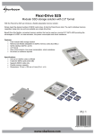
5. Package content
FANTEC MR-35DU3e
- User manual
- AC Cable
- USB Cable
- eSATA Cable
19