1
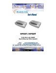
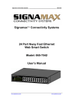
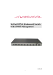
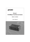
HFS24T
24- Port 10/100M
Rack Mount Switch
1
FCC Warning
This equipment has been tested and found to comply with the limits for a Class A
digital device, pursuant to Part 15 of the FCC Rules. These limitations are designed to
provide reasonable protection against harmful interference in a residential installation.
This equipment generates, uses and can radiate radio frequency energy and, if not
installed and used in accordance with the instructions, may cause harmful interference
to radio communications. However, there is no guarantee that interference will not
occur in a particular installation. If this equipment does cause harmful interference to
radio or television reception, which can be determined by turning the equipment off
and on, the user is encouraged to try to correct the interference by one or more of the
following measures:
•
•
•
•
•
Reorient or relocate the receiving antenna.
Increase the separation between the equipment and receiver.
Connect the equipment into a different outlet from the one that the receiver is
connected to.
Consult your local distributors or an experienced radio/TV technician for
help.
Shielded interface cables must be used in order to comply with emission
limits.
Changes or modifications to the equipment, which are not approved by the party
responsible for compliance, could affect the user’s authority to operate the equipment.
CE Mark Warning
This equipment complies with the requirements relating to electromagnetic
compatibility, EN 55022 class A for ITE, the essential protection requirement of
Council Directive 89/336/EEC on the approximation of the laws of the Member States
relating to electromagnetic compatibility.
LIMITED WARRANTY
Hawking Technology guarantees that every HFS24T 24-Port 10/100M Rack Mount
Switch is free from physical defects in material and workmanship under normal use
for two (2) years from the date of purchase. If the product proves defective during this
two-year warranty period, call Hawking Customer Service in order to obtain a Return
Authorization number. The warranty is for repair or replacement only. Hawking
Technology does not issue any refunds. BE SURE TO HAVE YOUR PROOF OF
PURCHASE. RETURN REQUESTS CANNOT BE PROCESSED WITHOUT
PROOF OF PURCHASE. When returning a product, mark the Return Authorization
number clearly on the outside of the package and include your original proof of
purchase.
IN NO EVENT SHALL HAWKING TECHNOLOGY’S LIABILITY EXCEED THE
PRICE PAID FOR THE PRODUCT FROM DIRECT, INDIRECT, SPECIAL,
INCIDENTAL OR CONSEQUENTIAL DAMAGES RESULTING FROM THE USE
2
OF THE PRODUCT, ITS ACCOMPANYING SOFTWARE OR ITS
DOCUMENTATION. Hawking Technology makes no warranty or representation,
expressed, implied or statutory, with respect to its products or the contents or use of
this documentation and all accompanying software, and specifically disclaims its
quality, performance, merchantability, or fitness for any particular purpose. Hawking
Technology reserves the right to revise or update its products, software, or
documentation without obligation to notify any individual or entity. Please direct all
inquiries to: [email protected].
3
Package Contents
Introduction
Features
Select Features: Summary
Hardware Description
Hardware Installation
N-way Process
Specifications
5
6
7
8
9
11
13
14
4
The complete HFS24T package consists of:
•
•
•
One HFS24T 24-Port 10/100M Rack Mount Switch
Four rubber feet with adhesive backing (rubber feet may already come
installed by manufacturer)
19” Rack Mount Kit
•
•
One Power Cord
One User’s Manual
Check to make sure that the unit was not damaged during shipping and that no items
are missing. If you encounter a problem, please contact your dealer.
Please read this user’s manual thoroughly, and follow the installation and operation
procedures detailed in the following pages.
5
The HFS24T 24-Port 10/100Mbps Rack Mount N-Way Switch is designed for easy
installation and high performance. The switch provides you with a flexible, reliable,
and affordable solution for your Ethernet network, and includes 24 independent
10Base-T/100Base-TX ports. The HFS24T enables the segmentation of large
networks into smaller, connected subnets, thus allowing you to experience improved
performance for demanding applications. Each port delivers up to 200Mbps
throughput, and is able to operate in either half or full-duplex modes.
The 24-Port 10/100Mbps Rack Mount N-Way Switch features an N-Way autonegotiation (or auto-sense) function (refer to the chapter titled, “N-way Process”),
which automatically adjusts the device for optimum operation. “Store-and-Forward”
architecture filters eliminate error packets and improve efficiency. The HFS24T also
utilizes auto-MDI/MDIX technology, which enables you to use either standard
Ethernet cables or crossover Ethernet cables to connect with other devices. Moreover,
the built-in Universal Power Supply allows you to easily install the switch without an
external power adapter.
The HFS24T is also ideal for use with multiple, high-speed servers to share bandwidth
within 10Mbps or 100Mbps workgroups. With maximum throughput of 200Mbps,
any port can be used to provide workstations with a congestion-free data pipe for
simultaneous access to the server. In addition, the switch can be expanded by
cascading two or more switches together. The switch can be cascaded from any port
and to any number of switches.
The Plug and Play HFS24T is powerful and reliable, and can run your high-end video,
graphic, multimedia, database, and mission-critical applications with ease.
6
•
•
•
•
•
•
•
•
•
•
Complies with IEEE 802.3 10Base-T and IEEE 802.3u 100Base-TX standards
(24) 10/100M auto-negotiation, auto-MDI/MDIX Ethernet ports
Supports store-and-forward architecture and performs forwarding and filtering at
non-blocking full wire-speed
Supports “10/100M” and “Link/Activity” LED modes with “Power” (on) auto
diagnostic
Supports IEEE 802.3x flow control for full duplex operation
Supports back pressure for half duplex operation
Supports 8K MAC address entries
320K Bytes buffer memory
Built-in universal power supply (100 - 240VAC)
EMI certifications: FCC Class A, CE mark
7
MAC Address Table and Learning
The switch features a MAC address table that is capable of 8K entries. Each entry is
used to store the address information of network nodes on the network, including
MAC address, port ID, etc. This information is critical for packet filtering and
forwarding.
When one packet comes in from any port, the switch will learn the source address,
port ID, and other related information in the address table. Thus, the content of the
MAC address table updates dynamically.
Filtering and Forwarding
When a packet comes in from a particular port on the switch, the destination address is
checked against the source address learning. The switch will look up the address table
for the destination address. If not found, the packet will be forwarded to all other
ports except the port from where the packet came in. If found, and the destination
address is located at a different port than the one from which the packet came in, the
packet will be forwarded to the port where the destination address is located, based on
the information in the address table. But if the destination address is located at the
same port as the one from which the packet came in, then the packet will be filtered.
Store-and-Forward
Store-and-forward architecture is a type of packet-forwarding methodology. With the
store-and-forward function, the switch will store the complete packet in the internal
buffer and perform a complete error check before transmitting to the network.
Therefore, no error packets will disturb the network. This results in increased
efficiency and stability.
8
This chapter provides a description of the front panel, rear panel, side panel and LED
indicators of the switch.
Front Panel
The front panel includes:
1. (24) 10/100M auto-negotiation, auto-MDI/MDIX RJ-45 Ethernet ports
2. Corresponding LED indicators along with one additional “Power” (on) LED
indicator.
Rear Panel
The rear panel includes a power cord input for the built-in universal power supply.
Side Panel
The side panels include mounting holes to be used when installing the switch onto a
standard 19” rack.
9
The LED indicators will help you monitor the status of each port and connected
segment. The functions of the LED indicators are described below.
LED Indicators
Power
10/100M
Link/Activity *
Description
The indicator is lit green when the power is on. Otherwise,
it remains unlit.
LEDs from the two rows labeled “10/100M” are lit when
there is a 100Mbps connection (or link) to a corresponding
port, and remain unlit when there is a 10Mbps connection.
LEDs from the two rows labeled “Link/Activity” are lit
when there is a connection to a corresponding port, and
blink whenever reception or transmission (i.e., Activity) of
data is taking place.
* If the port is connected but the Link/Activity LED is dark, check the following
items:
1.
2.
3.
4.
If the switch and connected devices are powered on.
The port’s cable is firmly connected to the switch and associated device.
The connecting cable is of the correct type.
If the connecting device and/or network adapter, is functioning properly.
10
The HFS24T is a Plug and Play network device and does not require any special setup
procedures. Connect the power cord and cables correctly, and the unit is ready for use.
Switch installation
1.
Place the switch in an appropriate location. When placing the switch, two
items need to be considered:
Convenient Location: The switch should be placed in a location that is
central to your home or office space and allows all computers and
networked devices to be connected to the switch.
Power: The switch must be placed in a location that is accessible to a
nearby electrical outlet.
2.
Power on the switch by connecting the power cord.
3.
Make sure that the “Power” LED is lit. If the “Power” LED does not light up,
check the power cord to ensure that it is properly connected to the power
outlet. If the “Power” LED still remains unlit, please contact your dealer for
support.
Ethernet Port Connections
Connect user machines, servers, additional switches, hubs, or other appropriate
devices to the Ethernet ports on the switch with either standard or crossover Ethernet
cables. (For switch-to-switch connections, only standard cables are needed because
each switching port supports auto-crossover.)
Make sure that the corresponding LEDs are working properly. (See previous chapter
for description.)
Note
Make sure that:
1.
There is proper heat dissipation from and adequate ventilation around
the switch.
2.
The cabling is away from power lines and sources of electrical noise
such as radios, transmitters and broadband amplifiers.
3.
Water or moisture cannot enter the unit.
11
Rack Mount Installation
The following describes a general sequence of steps for securing the unit on a rack:
1.
2.
3.
Place one mounting bracket over the bracket mounting holes on each side
panel of the unit.
Insert the screws (included in the rack mount kit) through the bracket and,
using a screwdriver, secure the screws into the bracket mounting holes on the
unit.
Place the unit onto the rack by securing the mounting brackets to the mounting
strips on either side of the rack. To do this, align the holes on the mounting
brackets with the appropriate holes on the mounting strips. Be sure to use
screws that are meant for use with the specific rack that you will be mounting
the unit on. (These screws are provided or specified by the manufacturer of
the rack, not by Hawking Technologies.)
12
“Auto-negotiation” (N-way) mode automatically sets the best possible bandwidth
(10Mbps, 100Mbps) when a connection is established with another network device.
Auto-negotiation (or auto-sense) functions are determined by these set data-transfer
rate priorities:
1.
2.
3.
4.
100Base-TX Full Duplex (200 Mbps)
100Base-TX Half Duplex (100Mbps)
10Base-T Full Duplex (20Mbps)
10Base-T Half Duplex (10Mbps)
Each port with N-way capability supports half/full duplex functions.
13
EMI Certifications
Operating Temperature
IEEE 802.3, 10BASE-T Ethernet
IEEE 802.3u 100BASE-TX Fast Ethernet
IEEE 802.3x Flow Control
(24) 10/100Mbps RJ-45 Ports
(Support auto-MDI/MDIX)
RJ-45 (10BASE-T): UTP Category 3,4,5
RJ-45 (100BASE-TX): UTP Category 5
Auto-negotiation (10Mbps, 100Mbps)
Auto-negotiation (Full-duplex, Half-duplex)
Power:
Lit green when power is on
10/100M:
Lit green when there is a 100Mbps
connection, unlit when there is a
10Mbps connection
Link/Activity: Lit for successful connection,
flashing for activity
320K
8K entries
10Mbps: 14,880pps/14,880pps
100Mbps: 148,800pps/148,800pps
FCC Class A, CE mark
00 - 500C (320 - 1220F)
Operating Humidity
10% - 90%
Power Supply
Dimensions
100 - 240VAC, 50 - 60Hz
330 x 230 x 44 (mm) (Width x Depth x Height)
13.00 x 9.05 x 1.75 (inches) (W x D x H)
Standards
Interface
Cable Connections
Network Data Rate
Transmission Mode
LED Indicators
System Buffer Memory
MAC Address Table
Filtering/Forwarding Rate
14