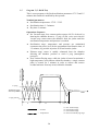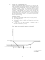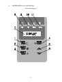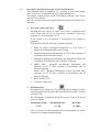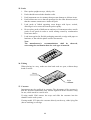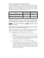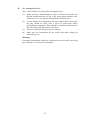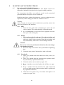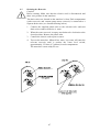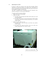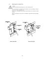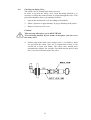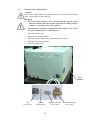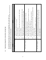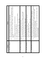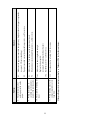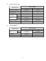
1
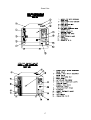
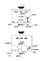
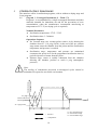
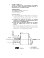
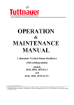
OPERATION & MAINTENANCE MANUAL Electronic Table-Top Pre and Post Vacuum Autoclave models 2540, 3870 EHS Cat. No. MAN205-0034005EN Rev. D Tuttnauer USA Co., Ltd., 25 Power Drive Hauppauge, NY 11788, USA, : (800) 624 5836, (631) 737 4850, Fax: (631) 737 0720 e-mail: [email protected] TABLE OF CONTENT DRAWINGS 1 2 3 4 5 6 7 8 PAGE NO. GENERAL ........................................................................................................... 4 1.1 Incoming Inspection ................................................................................. 4 1.2 Warranty .................................................................................................... 4 1.3 Warranty Statement .................................................................................. 4 GENERAL INFORMATION .............................................................................. 6 2.1 Introduction ............................................................................................... 6 2.2 Operating Conditions ................................................................................ 8 2.3 Stand – by heating mode ........................................................................... 8 2.4 Utilities ....................................................................................................... 8 2.5 Overall Dimensions for the 2540 model ................................................. 11 2.6 Overall Dimensions for the 3870 model ................................................. 12 2.7 Technical Specifications ......................................................................... 13 2.8 Electrical Specifications ......................................................................... 13 2.9 Construction ............................................................................................ 14 2.10 Water quality ........................................................................................... 14 2.11 Environment Emission Information ...................................................... 15 2.12 Symbol Description ................................................................................. 15 2.13 Directives and Standards ........................................................................ 16 STERILIZATION PROGRAMS ....................................................................... 19 3.1 Program 1 - Unwrapped Instruments (1 - Flash 273) ........................... 19 3.2 Program 2 (2 - WDry 273) ...................................................................... 20 3.3 Program 3 (3-WDry 250) ........................................................................ 21 3.4 Program 4 ................................................................................................ 22 3.5 Program 5 (5 - B&D Test) ...................................................................... 24 3.6 Program 6 (6 – Vacuum Leakage Test) ................................................. 25 KEYBOARD (keys and display) ........................................................................ 26 4.1 Description and Functions of the Front Panel Keyboard ..................... 27 4.2 Description of the Operational Messages .............................................. 30 4.3 Description of Displayed Error Messages and Safety Measures .......... 32 PRINTER ........................................................................................................... 34 5.1 Printer Operation .................................................................................... 34 5.2 DPU 20 Printer Handling ....................................................................... 36 5.3 DPU 30 Printer Handling ....................................................................... 37 PREPARATION BEFORE STERILIZATION ................................................ 38 DENTAL HANDPIECE STERILIZATION .................................................... 41 OPERATION ..................................................................................................... 43 8.1 Operating Instructions ............................................................................ 43 8.2 Lifting and carrying ................................................................................ 44 8.3 Loading and unloading the Device......................................................... 44 1 TABLE OF CONTENT (Cont.) DRAWINGS 9 10 11 12 PAGE NO. MAINTENANCE INSTRUCTIONS ................................................................ 46 9.1 Preventive and Scheduled Maintenance ................................................ 46 9.2 Draining the Reservoir ............................................................................ 47 9.3 Replacing the Air Filter .......................................................................... 48 9.4 Replacing the Door Gasket ..................................................................... 49 9.5 Replacing the Cartridge Fuse ................................................................. 50 9.6 Checking the Safety Valve ...................................................................... 51 9.7 Cleaning water outlet strainer ................................................................ 52 TROUBLESHOOTING FOR THE OPERATOR ............................................ 53 SPARE PARTS LIST ........................................................................................ 56 ACCESSORIES ................................................................................................. 56 2 TABLE OF CONTENT (Cont.) DRAWINGS PAGE NO. Suggested Site Drain Drawing ...................................................................................... 10 Front View ..................................................................................................................... 17 Rear View ....................................................................................................................... 18 Front Panel Keyboard ................................................................................................... 26 3 1 GENERAL Read the Operating Instructions carefully, before beginning any operation on the autoclave! 1.1 Incoming Inspection Upon receiving your Tuttnauer Autoclave carefully inspect the outside of the shipping carton for signs of damage. If any damage to the carton is found note the location with respect to the autoclave and check that area of the autoclave carefully once it is fully unpacked. Observe packing method and retain packing materials until the unit has been inspected. Mechanical inspection involves checking for signs of physical damage such as: scratched panel surfaces, broken knobs, etc. If any damage is found contact your dealer as soon as possible so that they can file a claim with the shipping carrier and also notify Tuttnauer. All Tuttnauer products are carefully inspected prior to shipment and all reasonable precautions are taken in preparing them for shipment to assure safe arrival at their destination. Note: Lifting and carrying should always be done by two people. 1.2 Warranty We certify that this instrument is guaranteed to be free from defects in material and workmanship for one year against faulty components and assembly. This warranty does not include routine cleaning and preventive maintenance to be performed according to instructions in section 9.1 (Preventive and Scheduled Maintenance). Tuttnauer warrantees all new EHS autoclaves for a period of one full year, covering both parts and labor. This one-year warranty covers defects in materials and workmanship on every part in the autoclave. This warranty does not apply to any instrument that has been subjected to misuse, neglect, accident or improper installation or application, nor shall it extend to autoclaves that have been repaired or altered outside the factory without prior authorization from Tuttnauer. Tuttnauer’s obligation is limited to the repair or replacement of parts for the autoclave. This warranty will be void if the unit is not purchased from an authorized Tuttnauer dealer. No other warranties or obligations are expressed or implied. The Autoclave should only be used in a manner described in this manual! 1.3 Warranty Statement To activate the warranty, the registration card must be completed and returned to Tuttnauer within fourteen (14) days of purchase or you may call our customer service department at the number listed below. For service on this product contact your dealer or Tuttnauer USA Co. No product will be received or accepted for repair without prior return authorization from Tuttnauer. All transportation charges to and from Tuttnauer must be paid by the owner of the autoclave. During the first 90 days after purchase of an autoclave, Tuttnauer will pay shipping costs on an individually evaluated basis and ONLY with pre-approval. 4 Note: If you have any questions or there are any difficulties with this instrument and the solution is not covered in this manual, please contact your dealer or Tuttnauer USA Co. Do not attempt to service this instrument yourself. Tuttnauer USA Co. 25 Power Drive Hauppauge, NY, 11788, USA : (800) 624 5836, (631) 737 4850, Fax: (631) 737 0720 e-mail:[email protected] 5 2 GENERAL INFORMATION 2.1 Introduction The EHS is a high speed, high vacuum, high capacity, hospital grade sterilizer with FDA cleared flash cycle. A built in vacuum pump and steam generator allows for increased load size and dramatically reduces total cycle time. The closed door drying system provides a faster and more thorough drying cycle. Six automatic cycles are available. Four sterilization cycles and two test cycles. EHS models are available in a 10” or 15” chamber. The EHS autoclave, models 2540 and 3870 are designed for the sterilization of wrapped and unwrapped instruments and related items found in dental, medical and veterinary clinics, first aid rooms, hospitals, laboratories etc. They are electrically – heated pre and post vacuum sterilizers, using steam as the sterilizing agent. A computerized control unit ensures a fully automatic sterilization cycle, and the control and monitoring of physical parameters. The EHS pre / post vacuum sterilizer has the following features: ¾ It is a Class B sterilizer in accordance with the European standard prEN 13060-2 ¾ It has a pre-vacuum conditioning stage ¾ It has a post-vacuum drying phase. ¾ It has a jacketed chamber ¾ It has a dual compartment water reservoir ¾ It has a complete water discharge system ¾ It has a PC friendly communication system The advantages of this pre / post vacuum sterilizer are: ¾ ¾ ¾ ¾ ¾ ¾ ¾ Dramatically faster overall cycle time Better and deeper steam penetration into loads Increased load size More thorough and efficient drying of materials Automatically maintained water reservoirs Immediate availability of steam for sterilization Non recycled water reduces maintenance The Vacuum pump: The pre and post vacuum stages are achieved with the use of a high volume liquid ring vacuum pump. The advantage of the pre-vacuum stage is felt during the sterilization stage. Vacuum removal of at least 99.5% of the air in the chamber allows the steam to penetrate deeper into packed materials. Deeper penetration allows for larger loads to be sterilized, thus saving time by having to run fewer cycles. The advantage of the post-vacuum stage is an efficient and thorough drying of bagged and wrapped items. This is accomplished by the combined use of a heated chamber and the vacuum removal of residual moisture. 6 The Jacketed chamber: This autoclave has a jacketed stainless steel chamber. The space between the walls of the chamber and jacket is used to generate and provide the steam required by the autoclave. The heating elements are located inside this cavity as is the mineral free water supplied by the reservoir. Steam is produced and maintained here as long as the unit is turned on, thereby eliminating waiting time and making possible steam on demand. This autoclave’s reservoir is divided into two compartments: The front compartment is for supplying the steam generator with mineral free water. It is replenished from a mineral free water source and is maintained automatically by high and low sensors and a computer controlled solenoid valve. The rear compartment is for supplying the liquid ring vacuum pump with tap water. It is replenished from a tap water source and is maintained automatically by high and low sensors and a computer controlled solenoid valve. Printer option: This autoclave can be equipped with an optional printer that prints the preset and actual parameters of each cycle (temperature, pressure and vacuum with respect to time). Computer interface: An outstanding feature of this autoclave is the communication system. This system allows interfacing with a personal computer for control and monitoring of the autoclave by means of a special software program. This communication system also enables the transmission of data from the autoclave through a modem - to a remote center for data logging or subsequent processing. This manual is intended for the user. It gives the user a general understanding of the instrument and the best ways to operate and take care of it, in order to obtain optimum effective results. After reading this manual, operating and maintaining the autoclave will be simple and easy. However since this instrument is built with high technology sensitive components, no attempt should be made by the user or any other unauthorized person to repair or recalibrate it. Only technical personnel having proper qualifications and holding technical documentation (including a technician manual) and adequate information are authorized to service the apparatus. 7 2.2 Operating Conditions This device is for indoor use only! The sterilizer should be loaded only with autoclavable material! The environment shall not exceed an ambient temperature of 104ºF (40ºC) and a relative humidity of 85% respectively. For optimal results from the first sterilization cycle, it is recommended to perform a B & D cycle (cycle # 5) at the beginning of each working day. 2.3 Stand – by heating mode While the autoclave is in the jacket heating stage, “St.By” is displayed in the upper right corner of the LCD screen. This announcement is maintained until the jacket reaches its working pressure, at which time the message will change to “READY”. When the unit is first turned on it will take approximately 10 - 20 minutes for the jacket to reach its working pressure and temperature. 2.4 Utilities For proper operation, these are the required utilities that need to be supplied: Site requirements for installation of a 2540 EHS 1. Counter top able to support a minimum 200 lb. * (the unit is shipped with a suitable stand - 26”W x 33”D x 34”H) 2. Counter space minimum 20”W x 32”D x 20”H * (see unit dimensions below) 3. City water supply 15 – 58 psi with shut off valve having ½” NPT male end. Higher rates of pressure will require the installation of a pressure reducer (58 psi max) The minimum flow rate required is 0.66 gal/min. (2.5 lit./min.). Installation of the valve should be 2” above counter height at the rear of the unit. 4. Mineral Free water supply 7 – 30 psi with shut off valve and ½” NPT male end. If the water pressure, at the autoclave inlet, is higher then 58 psi (4 bar), adjust the shut off valve for a low water flow into the mineral free water reservoir. The minimum rate of flow is 0.26 gal/min (1 lit/min). Installation of the valve should be 2” above counter height at the rear of the unit. * (an optional R.O. water system is available). 5. Electrical power 20A – 208V single phase. Connection required; flush mount receptacle 6-20R, within 1 foot of the rear of the unit. 6. Drainage should be to a 4” high 4” diameter air break, reducing down to a 1 ½” vented line with a trap. All drainage components must be able to withstand a non-continuous temperature of 140°F (60°C). Drain opening should be within 1 foot of the rear of the unit and no higher than 16” above the floor. The use of two ½”x 6" Milford Type Copper Coated Hangers is required for the positioning of the two drain hoses over the center of the air break and a 4” metal worm gear clamp to secure the hangers. The hangers will need to be bent at a 90º angle to allow for proper positioning and securing with the clamp. * (see attached drawing) 8 Site requirements for installation of a 3870 EHS 1. Counter top able to support a minimum 400 lb. * (the unit is shipped with a suitable stand - 26”W x 33”D x 34”H) 2. Counter space minimum 26”W x 39”D x 24”H * (see unit dimensions below) 3. City water supply 15 – 58 psi with shut off valve having ½” NPT male end. Higher rates of pressure will require the installation of a pressure reducer (58 psi max) The minimum flow rate required is 0.66 gal/min. (2.5 lit./min.). Installation of the valve should be 2” above counter height at the rear of the unit. 4. Mineral Free water supply 7 – 30 psi with shut off valve and ½” NPT male end. If the water pressure, at the autoclave inlet, is higher then 58 psi (4 bar), adjust the shut off valve for a low water flow into the mineral free water reservoir. The minimum rate of flow is 0.26 gal/min (1 lit/min). Installation of the valve should be 2” above counter height at the rear of the unit. * (an optional R.O. water system is available) 5. Electrical power 20A - 208V three phase, three power lines plus a ground. Connection required; flush mount receptacle or drop line with NEMA # L1520R, this is a twist lock connector, within 1 foot of the rear of the unit. 6. Drainage should be to a 4” high 4” diameter air break, reducing down to a 1 ½” vented line with a trap. All drainage components must be able to withstand a non-continuous temperature of 140°F (60°C). Drain opening should be within 1 foot of the rear of the unit and no higher than 16” above the floor. The use of two ½”x 6" Milford Type Copper Coated Hangers is required for the positioning of the two drain hoses over the center of the air break and a 4” metal worm gear clamp to secure the hangers. The hangers will need to be bent at a 90º angle to allow for proper positioning and securing with the clamp. * (see attached drawing) Caution! Wastewater should be brought into the public sewage network in accordance with the local rules or requirement i.e. only nonhazardous liquids shall be disposed in public sewage! 9 SUGGESTED SITE DRAIN DRAWING Discharge hoses from EHS Hanger with 90º bend 4” x 4” PVC air break Milford Type Copper Coated Hanger 1 ½” PVC to trap 4” Metal worm gear clamp 10 2.5 Overall Dimensions for the 2540 model Dimensions 2540 EHS inches mm A 20.0 510 B 16.7 425 C 28.1 715 D 43.3 1110 E 25 635 F (Front legs) 11.8 300 F1 (rear legs) 17.1 435 G 2.0 50 H 21.6 550 11 2.6 Overall Dimensions for the 3870 model Dimensions 3870 EHS inches mm A 26.0 660 B 20.7 525 C 34.5 875 D 55.0 1400 E 32.0 815 F (Front legs) 17.8 451 F1 (rear legs) 24.0 610 G 2.0 50 H 28.6 725 12 2.7 Technical Specifications Value Property Dia. Chamber 2540 3870 10” (254 mm) 15” (380 mm) Depth 18.7” (475 mm) Chamber volume 6.1 gal (23 lit.) 22.2 gal (84 lit.) Jacket volume 2.3 gal (8.5 lit.) 4.0 gal (15 lit.) Shipping weight 165 lb (75 kg) Shipping volume 21.5 ft3 (0.6 m3) 313 lb (142 kg) 27.2 ft3 (0.77 m3) Vacuum Reservoir volume (upper pump float switch) Jacket Max. Allowable Working pressure (MAWP) Tray dimensions (Internal) 0.7 gal (2.5 lit.) 0.7 gal (2.5 lit.) 0.7 gal (2.5 lit.) 0.7 gal (2.5 lit.) 40 psi (2.76 bar) 40 psi (2.76 bar) W 14” (35 cm) H Big 1” (2.5 cm) H 26” (67 cm) W 6.7” (17 cm) 11” (28 cm) H 0.8” (2 cm) Small 1” (2.5 cm) L 16.3” (41.5 cm) No. of trays IMS cassettes (optional) Load No. counter 2.8 30” (760mm) 26” (67 cm) 2 2 3 full & 3 half 15 full Counting from 0 to 9999 and nullifies. Electrical Specifications Value Property 2540 3870 3000W 6000W Amperage (A) 3200W 2ph +ground 208 VAC 50/60 Hz 15 6200W 3ph +ground 208 VAC 50/60 Hz 15 Frequency (Hz) 50/60 50/60 Heaters Power Total Power Voltage (VAC) Protection against electrical shock Class I (IEC 60601-1) 13 2.9 2.10 Construction The main parts of the autoclave are made of materials as indicated below: ♦ Chamber is built of stainless steel 316 L. ♦ Door is made of stainless steel 304. ♦ Trays are made of stainless steel 304. ♦ Water reservoir is made of hard plastic material. ♦ Door handle is made of hard plastic material, which is safe to touch and thermo-insulated. Water quality The distilled or mineral – free water supplied to the steam generator shall be according to the table below: Mineral Free Water qualifications (In compliance with EN 13060:2004) Silicium oxide. SiO2 Iron Cadmium Lead Rest of metals except iron, cadmium, lead Chloride (Cl) Phosphate (P2O5) Conductivity (at 20°C) pH value (degree of acidity) Appearance Hardness (Σ Ions of alkaline earth) ≤0.1 mg/kg ≤0.1 mg/kg ≤0.005 mg/kg ≤ 0.05 mg/kg ≤0.1 mg/kg ≤0.1 mg/kg ≤0.1 mg/kg ≤3 µs/cm 5 to 7 Colorless clean without sediment ≤0.02 mmol/l Attention: The use of water in the autoclave that does not comply with the table above may have severe impact on the working life of the sterilizer and can invalidate the manufacturer’s warranty. The suitability of the mineral free water to be used should be verified by testing in accordance with the above table, at an authorized laboratory using acknowledged analytical methods. 14 2.10.1 Water for the vacuum system and the Drain Cooling The feed water supplied to the liquid ring vacuum pump must meet the following requirements: ♦ Hardness: 0.7 - 2 mmol/l. ♦ Water temperature: shall not exceed 59°F (15°C). Note: The use of hard water in the vacuum pump may invalidate the warranty for the vacuum pump, since it can cause blocking of the rotor, which can damage the pump. 2.11 Environment Emission Information A. The peak sound level generated by the sterilizer is < 70 / dBA with background noise of 60 dB. B. The total heat transmitted by the sterilizer is: < 100 W / h (341 btu) for 2540 EHS < 150 W / h (512 btu) for 3870 EHS. 2.12 Symbol Description Caution! Consult accompanying documents Caution! Hot surface. Caution! Hot steam. Protective earth (Ground) On-Off 15 2.13 Directives and Standards Every autoclave meets the provisions of the following Directives and is designed, manufactured and tested in compliance with the following Standards: 2.13.1 Technical Directives 1. Medical device directive MDD/93/42/EEC. 2.13.2 Technical Standards 1. A.S.M.E. Code section VIII division 1 for pressure vessels. 2. UL3101-1 for Laboratory use Electrical Equipment. 3. UL/IEL/EN 61010-1 – Safety of electrical equipment …General requirement. 4. UL/IEL/EN 61010-2-041 – Particular requirement for steam autoclaves. 5. UL listed E206879 6. ANSI/AAMI ST-55 Table-Top Steam Sterilizer 2.13.3 Quality standards The manufacturing meets the following quality standards: 1. EN ISO 9001:2000 Quality System 2. ISO 13485:2003 – Quality systems – Medical devices Particular requirements for the application of ISO 9001. 3. 21CFR820 GMP for Medical Devices The manufacturer retains all supporting documentation. Both models were tested in accordance with ANSI/AAMI ST-55. 16 Front View 17 Rear View 18 3 STERILIZATION PROGRAMS The autoclave offers 4 sterilization programs, with or without a drying stage and 2 test programs. 3.1 Program 1 - Unwrapped Instruments (1 - Flash 273) Program 1 is recommended for a single unwrapped instrument and other materials intended for immediate use and for the prevention of cross contamination, when the manufacturer recommends autoclaving at temperatures of 273ºF (no drying cycle is required). Nominal Parameters ♦ Sterilization temperature: 273ºF - 279ºF. ♦ Sterilization time: 3.5 minutes. Operations Sequence ♦ Pre Vacuum stage; two vacuum pulses remove air by drawing the chamber down to –11.8 psig (24 Ih). At the end of the pre vacuum stage steam enters the chamber from the jacket until the sterilization temperature and pressure is reached. ♦ Sterilization stage; temperature and pressure are maintained constant at the preset level for the programmed sterilization time by periodic injection of steam from the jacket. ♦ Exhaust stage; steam is rapidly exhausted from the chamber allowing the chamber pressure to reach 0 psig (atmospheric pressure). TEMPERATURE PRESSURE (PSIG) Note: The sterility of instruments processed in unwrapped cycles cannot be maintained if exposed to non-sterile environment. 8.5 psig Ambient Pressure and Temperature TIME -11.8 psig (24 Ih) t1 t2 = Pressure = Temperature 19 t3 t1 = Pre Vacuum stage t2 = Sterilization stage t3 = Fast Exhaust stage 3.2 Program 2 (2 - WDry 273) Program 2 is recommended for wrapped instruments, porous load and other materials when the manufacturer recommends autoclaving at temperatures of up to 273ºF with a drying stage. Nominal parameters ♦ Sterilization temperature: 273ºF - 279ºF. ♦ Sterilization time: 8 minutes. ♦ Dry time: 20 minutes. Operations Sequence ♦ Pre Vacuum stage; four vacuum pulses remove 99.5% of the air by drawing the chamber down to -11 psig (22 Ih). At the end of the pre vacuum stage steam enters the chamber from the jacket until the sterilization temperature and pressure is reached. ♦ Exhaust stage; steam is rapidly exhausted from the chamber allowing the chamber pressure to reach 0 psig (atmospheric pressure). ♦ Post Vacuum Drying stage; while the jacket is heated to maintain a high temperature environment within the chamber, a single vacuum pulse is created for 20 minutes in order to release and remove residual moisture from any items within the chamber. TEMPERATURE Sterilization stage; temperature and pressure are maintained constant at the preset level for the programmed sterilization time by periodic injection of steam from the jacket. PRESSURE (PSIG) ♦ 8.5 psig Ambient Pressure and Temperature TIME -11 psig (22 Ih) t1 t2 = Pressure = Temperature 20 t3 t4 t1 = Pre Vacuum stage t2 = Sterilization stage t3 = Fast exhaust stage t4 = Post Vacuum Drying stage 3.3 Program 3 (3-WDry 250) Program 3 is recommended for delicate wrapped or unwrapped instruments and other material which the manufacturer recommends autoclaving at temperatures of up to 250ºF with a drying stage Nominal parameters ♦ Sterilization temperature: 250ºF - 256ºF ♦ Sterilization time: 30 minutes. ♦ Drying time: 20 minute. Operations Sequence ♦ Pre Vacuum stage; four vacuum pulses remove 99.5% of the air by drawing the chamber down to -11 psig (22 Ih). At the end of the pre vacuum stage steam enters the chamber from the jacket until the sterilization temperature and pressure is reached. ♦ Sterilization stage; temperature and pressure are maintained constant at the preset level for the programmed sterilization time by periodic injection of steam from the jacket. ♦ Exhaust stage; steam is rapidly exhausted from the chamber allowing the chamber pressure to reach 0 psig (atmospheric pressure). ♦ Post Vacuum Drying stage; while the jacket is heated to maintain a high temperature environment within the chamber, a single vacuum pulse is created for 20 minutes in order to release and remove residual moisture from any items within the chamber. TEMPERATURE PRESSURE (PSIG) Note: The sterility of instruments processed in unwrapped cycles cannot be maintained if exposed to non-sterile environment. 8.5 psig Ambient Pressure and Temperature TIME -11 psig (22 Ih) t1 t2 = Pressure = Temperature 21 t3 t4 t1 = Pre Vacuum stage t2 = Sterilization stage t3 = Fast Exhaust stage t4 = Post Vacuum Drying stage 3.4 Program 4 3.4.1 Program 4 - (4 - Fast 273) This program is available only in the 2540EHS Program 4 is recommended for wrapped instruments, nonlumened and materials that the manufacturer recommends autoclaving at temperatures of up to 273ºF with a drying stage. Nominal parameters ♦ Sterilization temperature: 273ºF - 279ºF. ♦ Sterilization time: 4 minutes. ♦ Dry time: 20 minutes. ♦ Sterilization stage; temperature and pressure are maintained constant at the preset level for the programmed sterilization time by periodic injection of steam from the jacket. ♦ Exhaust stage; steam is rapidly exhausted from the chamber allowing the chamber pressure to reach 0 psig (atmospheric pressure). ♦ Post Vacuum Drying stage: while the jacket is heated to maintain a high temperature environment within the chamber, a single vacuum pulse is created for 20 minutes in order to release and remove residual moisture from any items within the chamber. TEMPERATURE PRESSURE (PSIG) Operations Sequence ♦ Pre Vacuum stage; four vacuum pulses remove 99.5% of the air by drawing the chamber down to -11 psig (22 Ih). At the end of the Pre Vacuum stage steam enters the chamber from the jacket until the sterilization temperature and pressure is reached. 8.5 psig Ambient Pressure and Temperature TIME -11 psig (22 Ih) t1 t2 t3 = Pressure = Temperature 22 t4 t1 = Pre Vacuum stage t2 = Sterilization stage t3 = Fast exhaust stage t4 = Post Vacuum Drying stage 3.4.2 Program 4 - (4 - WDry 273) This program is available only in the 3870EHS Program 4 is recommended for wrapped instruments, porous load and other materials when the manufacturer recommends autoclaving at temperatures of up to 273ºF with a drying stage. Nominal parameters ♦ Sterilization temperature: 273ºF - 279ºF. ♦ Sterilization time: 8 minutes. ♦ Sterilization stage; temperature and pressure are maintained constant at the preset level for the programmed sterilization time by periodic injection of steam from the jacket. ♦ Exhaust stage; steam is rapidly exhausted from the chamber allowing the chamber pressure to reach 0 psig (atmospheric pressure). ♦ Post Vacuum Drying stage; while the jacket is heated to maintain a high temperature environment within the chamber, a single vacuum pulse is created for 20 minutes in order to release and remove residual moisture from any items within the chamber. TEMPERATURE PRESSURE (PSIG) ♦ Dry time: 20 minutes. Operations Sequence ♦ Pre Vacuum stage; four vacuum pulses remove 99.5% of the air by drawing the chamber down to -11 psig (22 Ih). At the end of the pre vacuum stage steam enters the chamber from the jacket until the sterilization temperature and pressure is reached. 8.5 psig Ambient Pressure and Temperature TIME -11 psig (22 Ih) t1 t2 = Pressure = Temperature 23 t3 t4 t1 = Pre Vacuum stage t2 = Sterilization stage t3 = Fast exhaust stage t4 = Post Vacuum Drying stage 3.5 Program 5 (5 - B&D Test) This is a test program, with fixed sterilization parameters 273ºF and 3.5 minutes that cannot be modified by the operator. Nominal parameters ♦ Sterilization temperature: 273ºF - 279ºF. ♦ Sterilization time: 3.5 minutes. ♦ Dry time: 2 minutes. ♦ Sterilization stage; temperature and pressure are maintained constant at the preset level for the programmed sterilization time, of 3.5 minutes, by periodic injection of steam from the jacket ♦ Exhaust stage; steam is rapidly exhausted from the chamber allowing the chamber pressure to reach 0 psig (atmospheric pressure). ♦ Post Vacuum Drying stage; while the jacket is heated to maintain a high temperature environment within the chamber, a single vacuum pulse is created for 2 minutes in order to release and remove residual moisture from any items within the chamber. TEMPERATURE PRESSURE (PSIG) Operations Sequence: ♦ Pre Vacuum stage; four vacuum pulses remove 99.5% of the air by drawing the chamber down to -11 psig (22 Ih). At the end of the Pre Vacuum stage steam enters the chamber from the jacket until the sterilization temperature and pressure is reached. 8.5 psig Ambient Pressure and Temperature TIME -11 psig (22 Ih) t1 t2 t3 = Pressure = Temperature 24 t4 t1 = Pre Vacuum stage t2 = Sterilization stage t3 = Fast exhaust stage t4 = Post Vacuum Drying stage 3.6 Program 6 (6 – Vacuum Leakage Test) Vacuum is produced in the chamber down to (P1) -12.5 psig (25.5 Ih). At this stage all the valves close. The autoclave remains in this stage for 5 minutes. This period enables the condition in the chamber to reach equilibrium. After the 5 minutes have elapsed the printer records the pressure that is referred to as P2. At this point the test begins and lasts 10 minutes. At the end of the test, the printer records the results. The pressure at the end of the test is referred to as P3. The rate of change of P3 to P2 shall not exceed 0.02 psi/min. If P3 to P2 exceeds 0.02 psi/min the printer will print “FAIL”. If P3 to P2 is within the required value, the cycle will end normally. Operations Sequence ♦ Vacuum is produced in the chamber down to -12.5 psig (25.5 Ih). ♦ The vacuum pump stops. ♦ The chamber is allowed to stabilize for 5 minutes then a test is done to establish P2. ♦ A second test is done after 10 minutes to establish P3 and to determine the vacuum lost (P3 - P2) PRESSURE (PSIG) Note: During the test period the autoclave is not heated. Ambient Pressure TIME P3 P2 P1= -12.5 psig (25.5 Ih) t1 t2 t3 t1 = Approx. 20 minutes t2 = 5 minutes t3 = 10 minutes 25 4 KEYBOARD (keys and display) Front Panel Keyboard 26 4.1 Description and Functions of the Front Panel Keyboard The command panel is comprised of 3 sections, on the lower section there are 6 keys; 3 command keys and 3 programming keys. The middle section consists of the LCD display with two rows and 16 characters on each line. The top section consists of 4 signal lights that indicate the status of the autoclave. 1. Sel. Cycle (select cycle) key Pressing this key selects, in order, one of the 6 programs listed below. Each time the key is depressed it advances to the next program (e.g. from program 2 to 3). If the system is set to program 6, pressing the key returns to program 1. This autoclave has the following available programs: 1. Flash for single unwrapped instruments at 273ºF with 3.5 minutes of sterilization time and no drying. 2. Wrapped instruments and materials at 273ºF with 8 minutes of sterilization and 20 minutes drying. 3. Wrapped or unwrapped instruments and materials at 250ºF with 30 minutes of sterilization and 20 minutes of drying. 4. Model 2540 - Wrapped non-lumened instruments and materials, at 273ºF with 4 minutes of sterilization and 20 minutes of drying. Model 3870 - Wrapped instruments, porous load and other materials, at 273ºF with 8 minutes of sterilization and 20 minutes of drying. 2. 5. Bowie & Dick Test 6. Vacuum Leakage Test Parameters key Pressing this key displays for 3 seconds the three parameters of the current program (except for the Bowie & Dick Test and the Vacuum Leakage Test). The information is displayed along the top row of the LCD screen and is as follows: Sterilization Temp Sterilization Time Dry Time 273ºF S = 4m D=1Øm After 3 seconds, or if the parameter key is pressed again, the screen returns to it’s original program display. 27 3. Start/ Stop key This key commands the following 3 functions: ♦ Starting the process. ♦ Stopping the process. ♦ Canceling the FAIL message from the command panel and opening the electric door locking if available. Starting the process: For starting a program this key is active only when the autoclave is in the “Ready” mode. If the door is closed, the water level in the reservoir is normal and the “Ready” indicator is on the screen then pressing this key starts the selected program. Stopping the process: For stopping a program this key is active while the autoclave is running a program, pressing this key at any stage of the program stops the process. Canceling the FAIL message At the end of an aborted program, the FAIL light is turned on and an error message is displayed on the screen indicating the cause of the failure. Pressing this key cancels the displayed message and switches off the FAIL light. 4. Program key This key is designed for programming the date and time as well as setting system parameters. The date and time settings are readily available to the machine operator. System parameters are only accessible with the appropriate access code and should only be changed by a properly trained and qualified service technician. When the PROGRAM key is pressed, the first to be displayed is the date with the cursor under the day. Each time the PROGRAM key is pressed the cursor advances to the next parameter, month, year, hour, minutes and then seconds. Using the UP (5) and DOWN (6) keys will change the value of the parameter above the cursor. After the date and time have been set, pressing the PROGRAM key again will show CODE: 000. A technician’s access code is required to proceed further and change system parameters. Information on all the system parameters can be found in the Technicians Manual. 28 5. UP key This key will increase the value displayed above the cursor, for either programming the clock or for setting system parameters by the technician. 6. DN key This key will decrease the value displayed above the cursor, for either programming the clock or for setting system parameters by the technician. 7. DISPLAY SCREEN The screen is an LCD display that consists of two display rows each containing 16 characters. The top row shows the current program and READY status. The bottom row shows real time temperature and pressure in the chamber. 8. START LED INDICATOR When the “START” LED indicator is on it indicates that the system is running a program. 9. FAIL LED INDICATOR When the “FAIL” LED indicator is on it indicates that the cycle has failed either, because the system parameters have not been maintained or the STOP key has been pressed. 10. WATER LED INDICATOR When the “WATER” LED indicator is on it indicates that there is a lack of water in the mineral free water reservoir. 11. DOOR LED INDICATOR If the “Start” key is pressed and the door is unlocked the light will signal twice, the buzzer will sound four times and a message “Door Unlock” will be displayed. If a cycle is in progress and fails because the door is unlocked the “FAIL” LED indicator will light and a message “Door Unlock” will be displayed. 29 4.2 Description of the Operational Messages The display is comprised of 2 rows, each row consists of 16 characters. 4.2.1 The upper row: On the left side of the upper row, 10 characters are allotted for the selected programs. 1 - Flash 273 Fast sterilization, fast exhaust, no drying. 2 - WDry 273 Lumened instruments, fast exhaust, with drying. 3 - WDry 250 All instrumentation, fast exhaust, with drying. 4 - Fast 273 Model 2540 - fast sterilization, non-lumened instruments, fast exhaust, with drying. Model 3870 - fast sterilization, wrapped instruments, porous load and other materials, fast exhaust, with drying. 5 - B&D Test Bowie Dick Test. 6 - Leakage Test vacuum leakage test. On the right side of the upper row, 6 characters are allotted for the selected programs. ♦ St.By (Stand By) ― Jacket heating stage. ♦ READY ― Jacket heating stage completed ♦ Vacum (Vacuum) ― Pre Vacuum stage ♦ Heat (Heating) ― Heating stage. ♦ Ster (Sterilization) ― Sterilization stage. ♦ Exh (Exhaust) ― Exhaust stage ♦ Dry (Dry Stage) ― Post Vacuum Drying stage ♦ Test ― Vacuum test stage When the PARAMETERS key is pressed the parameters of the selected program are displayed on the upper row. 4.2.2 The lower row: ♦ On the left side of the lower row 5 characters are allotted for the display of temperature in º F, in the form 273ºF. ♦ On the right side of the lower row, 5 characters are allotted for display of the chamber pressure. The actual pressure is continuously displayed at all stages of the process and between processes (standby). ♦ In the center of the lower row 6 characters are allotted for the display of the jacket pressure. The jacket pressure is displayed continuously unless the area is needed for another message. ♦ In case the process is aborted, the reason for the failure is displayed on the left side of the lower row, instead of the temperature. 11 characters are allotted for this error message. ♦ During the sterilization and dry stages, the countdown clock showing the amount of time left to the completion of the stage is displayed in the screen area between the readouts of temperature and pressure. 30 ♦ The format of the display is, MM:SS (two digits for minutes and two digits for seconds). ♦ On completion of the process, the END message is displayed in the screen area between the readouts of temperature and pressure. When a cycle is started by means of pressing the START key, the load number is displayed for 2 seconds on the left side of the lower row. Example 1: The screen display showing the autoclave between processes and program No.1 has been selected. 1Flash 273 St.By 230ºF J30.5 14.5 Temperature in chamber Pressure in jacket Pressure in chamber Example 2: The screen display showing the autoclave in the sterilization stage and program No.2 is running. The time left to completion is 3 minutes and 14 seconds. Selected program Stage 2 – WDry 273 273ºF Ster 03:14 30.1 Temperature Timer Pressure inºF Example 3: The screen display showing a process that has failed due to temperature drop during the sterilization stage of program No.3. Selected program 3 -WDry 250 Exh. LOW TEMP. 25.8 Error message 31 Stage chamber pressure 4.3 Description of Displayed Error Messages and Safety Measures Low Heat Message is displayed and sterilization does not start if the autoclave has not reached sterilization temperature after heating for 30 minutes. Low Temp. Message is displayed, FAIL indicator lights and cycle is aborted, if the temperature drops for more than 5seconds below the sterilization temperature. High Temp. Message is displayed, FAIL indicator lights and the cycle is aborted in one of the following cases: ♦ If temperature rises 6°F above sterilization temperature during the sterilization stage. ♦ Low Pres. High Pres. If temperature sensor is damaged, this message appears during the HEAT stage. Message is displayed, FAIL indicator lights, and the cycle is aborted if the pressure drops for more than 5 seconds below the pressure correlated to the sterilization temperature. This message is displayed, FAIL indicator lights, and the cycle is aborted if pressure rises above the pressure correlated to the sterilization temperature plus 6°F for more than 5 seconds. Low Vacuum Message is displayed and FAIL indicator lights if in the air removal stage a vacuum level of –11 psig (22 Ih) is not reached within 20 minutes after the cycle is started. Man. Stop Message is displayed and the FAIL indicator lights after the STOP key is pressed for longer than 1 second. Power Down No Message is displayed if a power failure occurs. An On message is printed on the printer with the date and time showing that there was a power interruption and when the power came back on. If the power is lost during the sterilization stage, then when power resumes, the system automatically aborts the cycle, exhaust will be performed according to the program requirements and a FAIL messages will be displayed and printed... If a power failure occurs during the Pre Vacuum or Heat stage, the cycle resumes and is continued until completion. Dry and Exhaust stages automatically resume operation once the power is back on. Door Unlock Message is displayed and the DOOR LED indicator flashes if the door is improperly closed and the START button is pressed to start the desired cycle. If the door becomes ajar during any stage of the cycle, the DOOR UNLOCK message is displayed and the FAIL indicator lights. 32 Add Water Message is displayed, the buzzer is activated four times and the "Water” LED illuminates if the water level switch indicates no water in the mineral free water reservoir and the START button is pressed. In this case the cycle will not begin until water is added and the START button is pressed. Ready Message is displayed if the autoclave is ready to begin a cycle. This will be when the pressure in the jacket has reached the proper pressure for the required cycle. Not Ready Message is displayed if the START key has been pressed before the pressure in the jacket has reached the proper pressure for the required cycle. St. By Message is displayed after the autoclave has been turned on and while the pressure in the jacket is rising to the pressure required to begin a cycle. Gen. Error Message is displayed, the buzzer is activated and the FAIL indicator illuminates when the water pump runs continuously for more than 10 minutes, attempting to fill the jacket. To cancel this alarm the main power switch must be turned off. After turning power back on, if the GEN.ERROR alarm occurs again after 2½ minutes, a service technician must be called. Vac Water Message is displayed when the low water level float, in the feed water reservoir, detects that the water level is too low. If a printer is installed on the system, then the printer will print any ERROR messages that appear on the LCD Display 33 5 PRINTER 5.1 Printer Operation The autoclave can be equipped with a character printer, which prints a detailed history of each cycle performed by the instrument (for the record or for subsequent consideration). The printing is made on thermal paper with 24 characters per line and prints the following information each time a cycle is run. ♦ Software version ♦ Date and time ♦ Selected program (with the parameters for that program) ♦ Sterilization time ♦ Sterilization temperature ♦ Sterilization pressure ♦ Success or failure of the performed cycle. ♦ Load number (1 – 99999) for identification ♦ Autoclave identifier ♦ Space for the operator’s signature When the sterilization cycle begins the printer starts printing the above data. After the preliminary printing, the autoclave starts performing the sequence of operations of the cycle. The measured values of temperature and pressure are printed at fixed time intervals, according to the phase of the process The data is printed from the bottom up, beginning with the software version number and ending with space for the operator’s signature (see the example below).. 34 PRINTER OUTPUT Operator :___________ Autoclave:001 02/03/2002 09:04:44 Load number: 00011 Cycle ended −−−−−−−−−−−−−−−−−−− D30:17 187.5°F 26.2Ihg ----------------------E26:15 230.2°F 01.3Psig ----------------------S24:21 276.1°F 31.0Psig * * * S18:19 275.5°F 31.9Psig S17:19 273.6°F 31.2Psig ---------------------H11:25 187.7°F 22.4Ihg ---------------------V09:34 232.4°F 08.8Psig * V00:00 076.0°F 00.2Ihg −−−−−−−−−−−−−−−−−−− Dry time: 020min Ster time: 008.0min Ster Temp: 273°F PROGRAM: 2-WDry 02/03/2002 08:17:30 EHSEn42-20USA DESCRIPTION To be filled in manually by operator. Autoclave identifying number. Date and time sterilization cycle ended. Load number. Useful for record keeping and scheduling maintenance The time, temperature and pressure during post vacuum drying The time, temperature and pressure during exhaust. The time, temperature and pressure during sterilization. Prints sterilization data every 1 minute. The time, temperature and pressure during sterilization. The time, temperature and pressure during sterilization. The time, temperature and pressure during heating. The time, temperature and pressure during pre vacuum. The time, temperature and pressure during pre vacuum. Drying time for selected program. Sterilization time for selected program. Sterilization temperature for selected program. Selected program: 2- 273ºF with dry cycle Date and time sterilization cycle began. Software version number Legend V H S E Vacuum stage Heating stage Sterilization stage Exhaust stage D Psig Ihg 35 Drying stage Pound per Square Inch Inch of Mercury 5.2 DPU 20 Printer Handling The printer is driven and controlled automatically by the control unit, while the autoclave performs a sterilization program. Figure 1 Figure 2 To set the paper roll in the printer perform the following steps: 5.2.1 Gently push the clips for removing the front panel, remove the panel and pull out the printer gently. 5.2.2 Set the paper roll on the shaft (See Figure 1). Since the outer and inner surfaces of the paper are different set the roll so that the printing surface is the outer. 5.2.3 Gently push the paper face down into insertion opening (A) in Figure 2. Keep pressing the feed switch (B) until the paper comes out from the print head (C). 5.2.4 When the paper emerges from the print head, insert it in the paper cutter (the slot in the front panel) and reassemble the front panel on the unit. The paper roll is set inside the unit and the printer is ready for use.. NOTE: If the paper is not pulled in by the rollers even when you press the feed switch (B) push the paper in. 5.2.5 To ensure a reliable operation of the printer perform the following: 5.2.5.1 Turn the main switch to the OFF position. 5.2.5.2 Turn the main switch to the ON position; press the feed switch at the same time. Verify that the printer performs an operation test by printing all the built-in characters The following precautions have to be taken ensuring the proper operation of the printer: ♦ Avoid contact between the paper and the hot parts of the autoclave, as the paper will be blackened. ♦ Do not pull out the paper roll from the paper insertion opening. ♦ Use only the 58mm. wide thermal paper rolls, supplied by your dealer. 36 5.3 DPU 30 Printer Handling 5.3.1 Setting Paper If the autoclave is equipped with A DPU 30 printer, follow the instructions in this paragraph. 1. Press the paper cover open button, and open the paper cover. Handle the paper cutter carefully not to cut your hand. 5.3.2 2. Set a paper roll as shown in the figure. 3. Close the paper cover by pressing both ends of the cover with the tip end of the paper emerging from the cutter. Maintenance 1. Wipe off the soiling on the printer surface with a dry soft cloth with a weak neutral detergent. After that, wipe the printer with a dry cloth. 2. Caution: Never disassemble the printer. Failure to follow this instruction may cause overheating or burning of the printer or the AC adapter. Or an electric shock, which may lead to fires or accidents. 3. Never use the printer in a place of extreme humidity or any place where it can possibly be splashed by any liquids. If any liquids get into the printer, it could lead to fire, electric shock, or other serious accidents. 4. Never touch the thermal head immediately after printing because it becomes very hot. Make sure that the thermal head is cool before setting papers or cleaning the thermal head. 5. Power OFF the printer in any of the following cases: 1. 2. 3. 6. The printer does not recover from an error. Smoke, strange noise or smells erupt from the printer. A piece of metal or any liquid touches the internal parts or slot of the printer. Notes on treatment of thermal papers: 1. Store the papers in a dry, cool and dark place. 2. Do not rub the papers with hard substance. 3. Keep the papers away from organic solvent. 37 6 PREPARATION BEFORE STERILIZATION This section applies to the sterilization of all instruments [except for dental handpieces]. For the preparation of dental handpieces, please refer to the handpiece manufacture’s instructions and see section 7 in this manual. CAUTION: The liquid cycle is not meant for the sterilization of liquids intended for direct patient contact. The purpose of packaging and wrapping items for sterilization is to provide an effective barrier against contamination during storage, once the items have been sterilized. Packaging and wrapping materials should be approved for use in a steam sterilizer and permit the removal of air and penetration of the steam during the sterilization process. The basic principle of determining the size, mass and contents of instrument and hollowware packs is that the contents are sterile and dry immediately upon completion of the drying cycle Instruments to be sterilized must be clean and free from any residual matter, such as debris, blood, pads or any other material. Such substances may cause damage to the instruments themselves or the sterilizer. 1. Clean instruments immediately after use. It is recommended that instruments be ultrasonically cleaned using Tuttnauer’s Clean and Simple enzymatic cleaning solution. 2. After ultrasonic cleaning rinse under tap water for 30 seconds and pat dry to remove residual minerals. If your tap water has a high mineral content then rinse a second time in a bath of distilled water or alcohol to remove minerals. 3. Launder textile wraps prior to reuse, but do not use bleach. 4. Follow the instrument manufacturer’s instructions for cleaning and lubricating instruments. 5. Be sure that instruments of dissimilar metal (stainless steel, carbon steel, etc.) are separated. Carbon steel instruments should be bagged or placed on autoclavable towels and not directly on stainless steel trays. (Mixing will result in the oxidation of these metals). 6. Do not place materials to be sterilized directly on the chamber’s wall. Place the material only on trays, rack, etc. 7. Check the manufacture’s instructions as to the proper procedure for sterilizing each item. 8. Place a sterilization indicator in each tray or inside each wrapped pack. 9. All instruments must be sterilized in an open position. 10. Use single-use wraps once only and discard after use. 11. Verify that the packaging method is in accordance with good practice approach and the packaging materials are in accordance with the applicable standards (e.g. EN868 series). 38 12. At least once per week use a biological spore test (Bacillus Stearothermophilus) in any load to insure proper sterilization. (Be aware testing standard may vary). 13. Place instruments with ratchets opened and unlocked or clipped on the first ratchet position. 14. Disassemble or sufficiently loosen multiple-part instruments prior to packaging to permit the sterilizing agent to come into contact with all parts of the instrument. 15. Tilt on edge items prone to entrap air and moisture, e.g. hollowware, so that only minimal resistance to air removal, the steam passage and condensate will be met. 16. Load items within the boundaries of the tray so that they do not touch the chamber walls, or fall off when the tray is inserted into the autoclave. 17. The operator may use racks to allow for adequate separation of packaged instruments. 18. Load trays loosely to capacity. Instruments should be loaded one level deep only 19. Do not overload the sterilizer trays. Overloading will cause inadequate sterilization and poor drying. maximum load is as follows: Maximum solid load for model 2540 is 13. lbs and for model 3870 is 44 lbs. Maximum textile load for model 2540 is 4.5. lbs and for model 3870 is 15.4 lbs. 20. Make sure that all instruments remain apart during the sterilization cycle. 21. Empty canisters should be placed upside-down, in order to prevent accumulation of water. 22. Allow a distance of approximately 1” (2.5 cm) between trays or cassettes to permit steam circulation. 23. Wrapped instruments should be packed in material that will allow steam penetration and promote drying, such as autoclave bag, autoclave paper, or muslin towels. 24. Do not stack pouches. It is recommended that a Tuttnauer Pouch Rack be used. This will allow the operator to place pouches on their side, which will increase capacity and provide proper spacing to ensure steam penetration and promote adequate drying. 39 25. Packs 1. Place packs upright on trays, side by side. 2. Packs should not touch the chamber walls. 3. Pack instrument sets in a manner that prevents damage to delicate items. 4. Pack hollowware sets so that all openings face the same direction and so that the contents cannot move inside the pack. 5. Load packs of folded operating room drapes with layers vertical, allowing air to be removed from the packs rapidly. 6. Do not place packs of hollowware and trays of instruments above textile packs or soft goods in order to avoid wetting caused by condensation from items above. 7. Load items packed in flexible packaging materials on edge with paper to laminate, or flat with the plastic surface downwards. Note: The manufacturer’s recommendations shall be observed, concerning the sterilization data for each type of material. 26. Tubing When placing in a tray, make sure that both ends are open, without sharp bends or twists. Wrong Right 27. Cassettes Instruments may be sterilized in cassettes. The advantage of the cassettes is that the sterilized instruments may remain organized in the cassettes ready for use, while stored in a sterile area. If using model 2540 remove the trays and slide the cassettes into the chamber on the rack system. If using model 3870 place the cassettes directly on the tray, either lying flat (but no stacking) or on edge. 40 7 DENTAL HANDPIECE STERILIZATION Up to 5 dental handpieces may be sterilized concurrently in the autoclave in the wrapped or unwrapped mode. No additional articles should be sterilized concurrently with the dental handpieces. You should follow the handpiece manufacturer's instructions regarding cycle times and temperatures. Where those instructions have not been provided, you may use one of the automated programs for wrapped and unwrapped instruments as follows: Cycle Time (minutes) Temperature (ºF) Unwrapped Instruments (Program 1) Wrapped Instruments (Program 2) 3.5 273 8 273 Caution: Some dental handpieces may be contraindicated for exposure to high sterilization temperatures. The electronic control system permits the sterilization temperature to exceed the set temperature by 6°F. Hence, when utilizing one of the automated programs, the sterilizer may reach a temperature as high as 279°F. Loading: No more than 5 dental handpieces, and only dental handpieces, should be sterilized during the same sterilization cycle. This was the worst case scenario validated during testing. Users selecting other load configurations should validate the process to ensure effective sterilization. When loading, sufficient space should be allowed between each handpiece to allow effective steam penetration. Tuttnauer recommends the review of ANSI/AAMI publication ST-42-1998 entitled: "Steam sterilization and sterility assurance using table-top sterilizers in office-based, ambulatory-care, medical, surgical and dental facilities." A. For Wrapped Cycles: (For unwrapped cycles, please skip to B). (1) Remove all trays, except for the bottom tray, from the sterilization chamber. (2) Place in the sterilization chamber a five position, stainless steel pouch divider specifically designed for paper/plastic pouches that will stand on edge during sterilization. The pouch divider should be placed in the center of the bottom tray level to the sterilizer. (3) Seal each handpiece in a 3.5" x 9" paper/plastic peel pouch. (4) Positioning the pouches in the pouch divider depends upon the number of dental handpieces being sterilized. No more than 5 handpieces should be sterilized during any single cycle. In all cases, the pouches should be positioned standing on edge and evenly distributed in the handpiece rack. The sides of the pouches should alternate, such that the paper side of one pouch stands next to the plastic side of the next pouch. 41 B. For Unwrapped Cycles: Note: Trays need not be removed for unwrapped cycles. (1) Before placing a dental handpiece onto a sterilizer tray, make sure that the instruments that are not of the same metal (stainless steel, carbon steel, etc.) are separated and placed in different trays. (2) In case carbon steel instruments are used with stainless steel trays, the tray should be lined with a towel or paper-wrap before positioning the instrument. There should be no direct contact between the carbon steel and the stainless steel trays. (3) Place a sterilization indicator strip in each tray. (4) Make sure the instruments do not touch each other during the sterilization cycle. Warning: Unwrapped instruments should be considered not sterile after processing once exposed to a non-sterile environment. 42 8 OPERATION 8.1 Operating Instructions 1. Open the main feed-water supply valve. 2. Open the mineral-free water supply valve. 3. 4. 5. 6. 7. 8. 9. Ensure the drain is connected. The drainage hose must be fixed very securely to the drain when water is released to reduce the risk of injury to personnel. Turn on the rocker switch mounted on the front panel to activate the control circuits. Wait until “READY” appears in the display. Set the clock for the proper date and time, by means of the PROGRAM key (4), UP (5) and DOWN (6); see paragraph 4.1. Press the SELECT key (1) to select the required program .The name of the program is displayed indicating the program has been selected. 7.1 It is recommended to run a B & D cycle as the first cycle each working day. To check the program parameters prior to running the program press the Parameters key (2). Load the material to be sterilized into the chamber, and close the door. Note: In order to ensure the door is fully sealed, tighten the door bolt until “hand-tight”. Do not over - tighten the bolt as this may result in damage to the gasket. Should the autoclave fail to reach the sterilizing temperature/ pressure, always check if the door is fully sealed. If not, tighten the door bolt further, as described above, until completely sealed. 10. Press the START key (3) to put the autoclave in operation. The autoclave starts performing the sequence of operations. The actual measured values of the clock, pressure and temperature are displayed continuously and printed every minute during sterilization stage and at the minimum and maximum pressure points for other stages. The messages St.By, READY, Vacum, Heat, Ster., Exh, Dry and Test are displayed at the right side of the upper line. If the operator presses the START key and the door is not completely closed, the process will not start and the DOOR light flashes for 4 seconds. 11. Drying is performed by means of the vacuum pump and heated chamber. All programs have the ability to perform a vacuum assisted drying stage, to remove unwanted moisture from instruments or other material that has been sterilized. The drying time is adjustable depending on individual needs. Program 1 intended for unwrapped instruments comes set to 0 minutes, all other sterilization programs are set to 20 minutes. All drying stages begin after the steam exhaust stage. 43 12. At the end of the cycle a buzzer rings and the START light switches OFF. The message “END” is displayed. The exhaust valve is opened to prevent formation of a vacuum, if the door is not opened immediately. In the event of program failure, the exhaust valve is opened, a continuous sound followed by beeps is output, the FAIL indicator is lit and the appropriate error message is displayed. 13. Open the door and unload the sterilized material from chamber. 14. At the end of the day switch off the power by means of the rocker switch on the front panel. Attention! The pressure and temperature of the jacket decreases very slowly when the equipment is turned off. 8.2 Lifting and carrying Caution: Before moving the autoclave, Make sure that the electric cord is disconnected from the power, that all hoses are disconnected from water supply and drain and there is no pressure in the chamber. 1. Disconnect the power supply cord. 2. Disconnect the water and drain hoses. 3. Drain the water from the reservoir and vessel. To avoid injuries, lifting and carrying should be done by at least two people. Do not drop this device! 8.3 Loading and unloading the Device 8.3.1 Safety Protective equipment and clothes and other safety instructions should be implemented in accordance with local and national regulations and/or rules! For proper sterilization - Do not overload the chamber. Only autoclavable products shall be used; for sterilization of unknown materials or instruments please refer to the instructions of the manufacturer of these items. 8.3.2 Loading Correct loading of the autoclave is essential to successful sterilizing for several reasons. Efficient air removal from the chamber and the load will permit effective steam penetration and saturation, and allow proper drainage of condensate. Additionally, correct loading will reduce damage to packs and their contents and maximize efficient use of the sterilizer. For detailed loading instructions, see para. 6 (Preparation before sterilization) 44 8.3.3 Unloading On completion of the cycle, the load shall be immediately removed from the sterilizer and a visual inspection made to ascertain that the load is dry, and that sterilizing indicators have made the required color change. Do not touch the strainer’s cover, mounted on the left side of the autoclave, during or shortly after operation. Touching the hot strainer’s cover may cause severe injuries. 45 9 MAINTENANCE INSTRUCTIONS 9.1 Preventive and Scheduled Maintenance The maintenance operations described in this chapter need to be followed as indicated to keep the device in good working condition. The instructions that follow can easily be carried out by un-trained personnel and do not require a service technician. Should the need arise, technical assistance or a service technician can be requested by either calling your dealer or Tuttnauer USA Co. Warning: Before carrying out any preventive maintenance operation, ensure that there is no pressure in the autoclave. 9.1.1 Daily 1. Clean the door gasket with a mild detergent, water and soft cloth or sponge. The gasket should be clean and smooth 2. 9.1.2 It is recommended to run a B & D test (program 6) as the first cycle each working day. Weekly 1. Take out the tray holder and trays. Clean the tray holder and trays with detergent or a non-abrasive stainless steel cleaner and water, using a cloth or sponge. Rinse the tray holder and trays immediately with water to avoid staining the metal. Caution Do not use steel wool, steel brush or bleach as this can damage the chamber and trays! 9.1.3 2. Put a few drops of oil on the 2 door pins and door tightening bolt. 3. Clean the outer parts of the autoclave with a soft cloth. Periodically 1. Once every month clean and check the safety valve (see para. 9.6). 2. Once every month drain the generator (this operation shall be performed by a qualified technician). 3. Clean the strainer once a month (see para. 9.7). 4. Every 6 months or as needed replace the air filter, (see para. 9.3). 5. Every 6 months clean the electronic box with compressed air, from inside outward (this operation shall be performed by a qualified technician). 6. Check the door gasket every 12 months and replace it if required (see para. 9.4). 46 9.2 Draining the Reservoir Caution! Before starting, Make sure that the electric cord is disconnected and there is no pressure in the autoclave. The drain valves are located on the autoclave’s front. Each compartment (jacket reservoir and vacuum pump water reservoir) is connected to a separate drain valve (see location drawing below). 1. 2. 3. 4. Connect the supplied plastic tube to the relevant valve and turn drain valve counter clockwise (1 turn). When the water reservoir is empty, turn drain valve clockwise to the closed position. Remove the plastic tube. Connect the electric cord to power source. Turn on the autoclave. Mineral free water / tap water will enter the relevant reservoir until it reaches the water level switch, approximately 2.5 liters (0.7 gallons) in each compartment The autoclave is now ready for use. 47 9.3 Replacing the Air Filter In order to “break” the vacuum, at the end of the dry phase, filtered atmospheric air enters the chamber via a solenoid valve. The filtration of the air is performed by the bacteriological filter that is placed at the inlet of the chamber, through a solenoid valve. The filter is mounted near an opening on the left sidewall of the autoclave enclosure, to ease access for replacing it. To replace the filter proceed as follows: 1. Remove the cover of the opening. 2. Remove the filter: 2.1 On model 2540, disconnect the filter from the filter cover and the flexible tubing. 2.2 On model 3870, cut the tie wrap connecting the flexible tubing to the filter. Disconnect the filter from the filter cover and the flexible tubing. 3. Replace the filter with a new one: 3.1 on model 2540, connect the filter to the filter cover and the flexible tubing. 3.2 On model 3870, connect the filter to the cover and to the flexible tubing and secure it with a tie wrap. Service cover with air filter 48 9.4 Replacing the Door Gasket Pull off the gasket from the door groove and install the new gasket referring to the drawings as above points 1, 2 and 3. Caution! This gasket is designed with a trapezoidal cross section. The gasket should be placed with the widest side towards the door. 49 9.5 Replacing the Cartridge Fuse Caution Make sure that the electrical power cord is disconnected! Use a screwdriver to unlock the fuse holder cover by turning it counter clockwise ¼ turn, and pull it out. Insert a new cartridge into the holder and turn the cover clockwise until locked. Make sure that the correct fuse is installed as specified in the drawings below: Model 2540 EHS Model 3870 EHS 50 9.6 Checking the Safety Valve The safety valve is located in the water reservoir In order to prevent the safety valve from becoming blocked, it is necessary to allow the steam pressure to escape through the valve. This procedure should be done every month as follows: 1. 2. 3. Operate the sterilization cycle according to the manual. Allow a pressure of approximately 30 psig to build up in the jacket. Remove water reservoir cover Caution! This next step will expose you to HOT STEAM To avoid being burned, by hot steam, do not place your face over the safety valve. 4. Pull the ring of the safety valve using a tool, i.e. screwdriver, hook etc and open the safety valve for 2 seconds then release it. Be careful not to burn your hands. The safety valve should close automatically within a few seconds, if not then turn the unit off and have a service technician replace the valve. 51 9.7 Cleaning water outlet strainer Caution! Before proceeding, Make sure that the electric cord is disconnected and there is no pressure in the autoclave. Warnings 1. Do not touch the strainer’s cover, mounted on the left side of the autoclave, during and shortly after operation. Touching the hot strainer’s cover may cause severe injuries. 2. If maintenance operation is performed while strainer cover is hot, use heat resistant gloves to avoid injuries. 1. 2. 3. 4. 5. Open the strainer cap. Remove the strainer element. Rinse the strainer with water, using a brush if necessary. Reinstall the strainer element. Close the strainer cap. Water strainer Cap FIL175-0027 Gasket Strainer element GAS082-0008 FIL175-0046 52 Strainer Housing FIL175-0051 53 ‘Low Vacuum’ is displayed ‘Gen. Error’ is displayed 3. 3.1 2.5 2.4 2.2 Water level electrode does not sense water for a period of 10 minutes. Check water level in the reservoir. If water level is low and lower float switch is not stuck – call for service. if the above did not solve the problem – call for service. If not - fix water supply. Verify that the vacuum pump water reservoir contains the adequate quantity of water. Make sure the tube on the “Exh. from pump” connection is not blocked. (see para. 9.5, Replacing the Cartridge Fuse). Make sure the pump is running. Check the pump fuse and replace it if necessary. (see para. 9.4, Replacing the Door Gasket) Check the door for leakage and replace the door gasket, if necessary. Cut-off thermostat may have been activated. Press the cut-off reset button. 1.5 2.1 Make sure the circuit breaker has not tripped. Reset circuit breaker if necessary. (see rear view drawing) Make sure the power cord is properly connected to the machine and the mains. (see front view drawing). Make sure the main switch is in the ‘On’ position. Verify that there is electric power in the electric network. Solution 1.4 1.3 1.2 The machine is not responding 1.1 Problem This troubleshooting chart enables the user to solve minor malfunctions, prior to requesting service Only technical personnel having proper qualifications and holding technical documentation (including a technician manual) and adequate information are authorized to service the apparatus. TROUBLESHOOTING FOR THE OPERATOR 2. 1. 10 54 ‘Low Pres’ is displayed The printer does not print. 7. ‘Low Water’ is displayed 5. 6. ‘Low Heat’ is displayed 4. Problem Check that there is no leakage of steam at the door. If yes, verify that the door is closed according to instruction in para. 8.1 if leakage continues, replace door gasket according to para.9.4. Verify that there is enough mineral free water in the reservoir. Check 1.25A fuse and replace if burnt. Check electrical supply fuses. Replace or reset tripped fuse as needed. If the above did not solve the problem – call for service. 4.2 4.3 4.4 4.5 4.6 If the above did not solve the problem – call for service. 5.3 Switch off the machine and switch it back on while pressing the feed button on the printer. If the printer prints a test printout, the printer is O.K. and there is a problem with the electronics. Call for service to solve the problem. 7.2 If the printer does not print the test printout, there is a problem with the printer. Call for service to solve the problem. Make sure the paper is inserted in the printer. (see para. 5.2, Printer handling) If the above did not solve the problem – call for service. 7.1 6.2 (see para. 9.4 Replacing the Door Gasket) Check the door for leakage and replace the door gasket if necessary. If there is water then possibly the water pump fuse in burnt. Replace fuse. 5.2 6.1 If no water then possible faulty mineral free water supply. Fix water supply. 5.1 Check if there is water in the mineral free water reservoir. Make sure the machine has the proper amount of sterilization load. 4.1 Solution 55 When the machine is switched on, the printer’s paper is fed continuously. 9. Make sure the ‘feed button’ on the printer is not stuck. If button is not stuck and problem persists – call for service. 9.2 If paper is inserted correctly and problem persists – call for service. (see para. 5.2, Printer handling) Make sure the paper is mounted in the right way. Only one side of the paper is printable. 9.1 8.2 8.1 Solution 11.1 Fast exhaust valve is faulty. Call for service If the problem persists, contact your dealer or Tuttnauer USA for further assistance. 11. When running a cycle, the exhaust stage takes a very long time. 10.2 If problem persists – call for service. (see para. 9.4 Replacing the Door Gasket) 10. The machine is leaking at the 10.1 Make sure the door is tightened enough. door Replace the door gasket. The printer prints, but nothing is printed on the paper. 8. Problem 11 SPARE PARTS LIST PART NUMBER DESCRIPTION 2540 01910106 ELE035-0011 FIL175-0016 02610023 01610406 3870 01910106 ELE035-0011 FIL175-0016 02610019 01610406 01610406 DPU20 01610100 DPU30 FIL175-0027 FIL175-0006 GAS082-0008 THE002-0022 FIL175-0027 FIL175-0006 GAS082-0008 1.25A fuse water pump 6.3A fuse vacuum pump 0.2µ HEPA filter Door gasket DPU20 Printer paper DPU30 Printer Cap for ¼” strainer Strainer element Teflon gasket 4 mm 12 ACCESSORIES PART NUMBER DESCRIPTION 2540 Tray Large Small CT520010 Tray handle Tray holder Silicon drain tube CT530020 CT510010 02620016 56 3870 CC520010 CC520020 CC510010 02620016