1
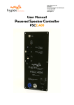
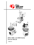
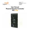
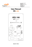
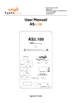
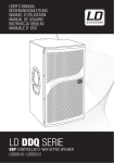
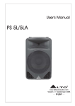
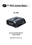
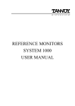
Hypex Electronics BV
Kattegat 8
9723 JP Groningen, The Netherlands
+31 50 526 4993
[email protected]
www.hypex.nl
User Manual
Powered Speaker Controller
PSC2.400
User manual R5
PSC2.400
Table of contents
Product description .............................................................................................................. 3
Type remarks...................................................................................................................... 3
Features .............................................................................................................................. 3
Applications........................................................................................................................ 3
Connections........................................................................................................................ 4
System information ............................................................................................................. 6
Description.......................................................................................................................... 6
Audio performance data ................................................................................................... 6
Hardware Architecture ...................................................................................................... 7
Digital audio input............................................................................................................. 7
Controllers .......................................................................................................................... 7
Clip limiter .......................................................................................................................... 7
Product overview................................................................................................................... 8
Hardware part .................................................................................................................... 8
Software installation ......................................................................................................... 9
Control panel ................................................................................................................... 9
Filter design...................................................................................................................10
Graph Area.....................................................................................................................11
Filter Definition Area ....................................................................................................11
Settings Window...........................................................................................................11
Work flow .......................................................................................................................11
Measurement ................................................................................................................11
Designing filters............................................................................................................13
Download ..........................................................................................................................14
Firmware update.................................................................................................................14
Safety precautions..............................................................................................................15
Instructions For Installation..............................................................................................15
Recommended Operating Conditions for the SMPS....................................................16
General Performance data for the SMPS ......................................................................16
Mains selection ...................................................................................................................17
Technical data .....................................................................................................................18
-2-
User manual R5
PSC2.400
Product description
Type remarks
Use only a version 1.4 or higher of the Hypex Filter Design program! In earlier versions the PSC is
not yet implemented.
The first time the PSC2.400 is used all biquads are zero, so there are no filters installed
When you switch to Bridged mode please be sure to connect your speakers like described in this
manual
Do note that the Firmware update differs to the AS2.100 firmware update.
After updating the firmware please use the combining PC software downloaded from our website,
www.hypexshop.com
Firmware version 1.2 (July 2011)
Features
2x UcD400OEM amplifier
Switch mode power supply
Balanced audio in
Balanced audio through loop
Two channel active filtering
Fully user-configurable filters
Firmware update by USB
DSP supply voltage dependant clip limiter
Digital version with AES/EBU input
Applications
This module can be used for the following setups:
Active 2-channel system
Active power sub-woofer
And with 2 modules it is also possible to set up a 3-channel system with one module for the separate
Subwoofer, and a second module for the top in a 2-channel system.
-3-
User manual R5
Connections
Figure 1
Overview of the connections on the front of the PSC2.400
Function
USB input
1
Select button
2
Preset LED’s
3
Clip detect LED
4
Analogue Link
5
Analogue Audio Input
6
Power input
10
Power output
11
On/Off switch
12
-4-
PSC2.400
User manual R5
PSC2.400
Digital version only:
AES Though
7
AES 3 Input
8
AES input channel LED’s
9
Figure 2
Overview of the connections on the back of the PSC2.400
Function
1
J16, Speaker 2
J14, Speaker +
3
J17, Speaker 4
J15, Speaker +
* For bridged mode use J14 and J15. Signal on J14 is inverted
Figure 3
Function
Jumpers placed is normal function
Jumpers not placed lowers High channel gain with 10dB, this must be corrected in
Hypex Filter Designer under Tools>Options *
* Only available on hardware version PSC2 V3 and up
1
-5-
User manual R5
PSC2.400
System information
Figure 4: Block diagram
Two-channel active amplifier with DSP filter control.
Description
The PSC2 is a plate amp for use in powered speaker systems. As an active speaker controller, a PSC2
can form the basis of a powerful active two-way monitor.
Figure 4 shows the audio path of the PSC2. The module has two 400Watt UcD modules implemented
and is also available with a digital audio input AES/EBU, called the PSC2.400d version. The supply
voltage is provided by a Switched Mode Power Supply (SMPS400) module, also a module from Hypex
Electronics.
A PC controls the PSC2 through the USB port. This connection is used to upload the configuration
and filter settings. It will also be possible to update the firmware through USB.
Audio performance data
MBW=20kHz, unless otherwise noted. All filters set to unity. Noise levels unweighted.
Symbol Min
Typ Max
Unit Notes
Item
Input level
Vin
+18
dBu
Vin max
Output level
LS1
400*
W
Into 4 Ohms
LS2
400*
W
Into 4 Ohms
Signal/Noise
SNR
101
dB
ADC
107
dB
DAC
Total harmonic distorTHD+N
-90
dB
Without UcD400
tion+Noise
DSP sampling rate
Fs
48
kHz
Delay per channel
0
0
15000
us
Set in software
Supported digital sampling
Fs
32, 44.1, 48, 88.2, 96,
kHz
All input rates con-6-
User manual R5
rates
192
Gain
+16
Analogue Latency
1,12
AES Latency
3,58
* Note: Total power for the PSC2.400 is limited to 500Watts total
dB
ms
ms
PSC2.400
verted to 48kHz
volume at 0dB
Hardware Architecture
The standard version of the PSC2.400 has an analogue balanced audio input. This analogue signal is
converted to digital, processed by the DSP and then converted back to analogue. A microcontroller
controls the DSP and communicates with the PC and can set the presets. An unbalanced source may
also be applied, this signal is divided over the two input DAC’s to get better performance.
Digital audio input
The digital version of the PSC2.400d comes with an AES/EBU digital audio input. Incoming AES/EBU
is linked through directly to the output and send to the DSP through an asynchronous sample rate
converter (ASRC) for jitter removal. The ASRC chip scans its input for whichever signal is active.
When the module is set to “Auto input select”, in the control panel on the computer, the input source
is automatically switched to digital when present. If the digital audio is stopped the source will be
switched back to analogue.
Controllers
The PSC2.400 can only be controlled through USB. When the module is powered on it will automatically start up with the last settings. All setting, like volume and preset, are stored after a change is
made.
Clip limiter
The PSC2.400 has a build in clip protection. The module measures the supply voltage and uses this
value for the limiter. Figure 5 shows the response graph of the limiter.
The hold time is fixed to 100ms and the decay is set to 100dB/s.
Figure 5
When the limiter for either channel is active the Clip led will be lit.
Thermal protection
All modules fitted with Hardware ‘PSC2 V2’ or later, delivered since November 2010, have a build-in
thermal protection. This protection lowers the output gain 1 dB per degree starting at plate temperature of 70 degrees Celsius. The outputs will be completely muted when the temperature rises over 90
degrees.
-7-
User manual R5
Product overview
Before you can use the PSC2.400(d) in your
particular setup, you first have to set the right
settings. This is done by pc software, called
Hypex DSP filter design.
Please do not connect any speakers to your
system yet!
Hardware part
The PSC2.400 can be used in 2 ways, as a 2channel setup or as a one channel bridged
version for more power. This is selected in
software.
The module can store up to 4 presets. A preset
holds the complete filter-settings of both
channels. By this the user is able to make
different system settings for its speakers, for
example for different rooms and setups.
All of the presets are empty from factory
setup, therefore the filters must be downloaded
first. See section “examples”.
* note that for bridged mode both LS+
connections must be used, see section
Connections for more information
Figure 6
-8-
PSC2.400
User manual R5
PSC2.400
Software installation
System requirements:
•
Pentium class or higher
•
64MB RAM
•
USB1.0 or higher
Tested on Windows XP and Vista
All files are compressed in the setup.zip file. This zip file contains 1 DLL file for communication and
an .EXE file, which represents the Hypex DSP filter design program.
1. Unzip the setup.zip file on your hard disk
2. Open the “Hypex DSP filter design.EXE” by double clicking the file
Control panel
Now the program is ready for use. You will see the
following window, called the control panel.
Figure 7
When the program is running connect your module to your pc by the USB cable. Windows will automatically detect and install the HID-device. When the installation is done the connected the connection light will turn green. You can also manually make a connection by the “connect” button, on the
bottom right of the control panel.
Now you may adapt the settings of the module real time through USB. On the left side in the control
panel you see the Force input and active input groups. This shows you the settings of the audio inputs and lets you control these inputs (only for digital version).
Audio can be provided analogue and digital. The selection of any of these inputs can be automatic,
“auto detect”. This means that when any of the inputs is presented there will be switched to this
channel automatically. This is done by setting the analogue input as the standard source. During
analogue in the other two inputs are scanned for any valid signal. The first channel that contains
any valid audio is selected and becomes the new input source. But if you put in the USB cable but
you want to use the analogue input you can force the analogue input to be used. This can be done
for both inputs.
When the module selects one of the inputs this is shown by the active input lights.
Under the Setup select part the system setup can be selected. There can be chosen between:
2-channel
Bridged
Master on the left
Master on the left
Master on the right
Master on the right
* The channel assignment in analogue mode makes no difference because there is only one input
channel
-9-
User manual R5
PSC2.400
The last thing that can be controlled in this window is volume. This can be done by setting the scrollbar to a desired position or by typing the value in the volume field, the value is send when pressed
“enter”.
When the presets are installed they may be selected, the module will switch to the selected preset.
The presets can be filled in the “Filter design” section.
Filter design
When you want to make some filters for
your module they can be designed in the
“Filter design”. Under view there can be
switched between the control panel and the
filter design window.
The following pages will give you a
widespread instruction of the possibilities of
the program.
Figure 8
Figure 9
- 10 -
User manual R5
PSC2.400
Graph Area
The magnitude tab shows the imported driver responses, filters, individual biquads, individual filtered driver responses and the sum.
Colour
Function
Blue, thin
Measured woofer response
Green, thin
Measured midrange response
Red. thin
Measured tweeter response
Blue, thick
Filtered woofer response
Green, thick
Filtered midrange response
Red, thick
Filtered tweeter response
Light blue, thick
Response of filter, selected channel only
Orange, thick
Response of selected biquad
Black, thick
Sum response
Having all of these on at the same time quickly produces an intractable mess so these graphs can be
separately enabled or disabled in the filter definition area.
The impulse or step tabs show the time domain response of the imported drivers and the sum response, and are used to demarcate the anechoic portion.
Filter Definition Area
The two channel tabs, labelled Tweeter and Woofer are functionally identical. The top left frame is
used to import response files. The “select” button opens a file. The “show” checkbox turns display of
the measured graph on or off. The Common Settings box controls global gain (for each channel),
delay, and the visibility of plots.
The amplified channels have up to 12 biquads, selected using the “Biquad Section” radio buttons in
the middle. To the right is a settings area specific to the type of function selected. Unused biquads
are set to unity.
The selected biquad is edited by selecting a function and setting relevant parameters.
Settings Window
Figure 10
The settings window is under File > Settings… Measurement sampling rate sets the sample rate used
in the imported response files (typically 48kHz). Processor sampling rate is that of the Hypex DSP
hardware. Note that this setting does not control the sampling rate of the hardware. Rather, it informs the filter design application of what that sampling rate is. In short, leave this at 46,875kHz.
The select button opens a file dialogue box witch is not used in this application.
Work flow
Measurement
Measuring using the DSP unit set to “flat”
- 11 -
User manual R5
PSC2.400
Perform impulse response measurements for each driver separately. Save the entire impulse record –
truncation can be done later on the filter design program.
Measuring using an external amplifier
A separate amplifier may also be used for measuring the drivers, provided the amplifier’s output
impedance is as low as the DSP unit’s.
Importing response data
Select the tab for the channel you want to import and click “select”. The filter designer expects the
impulse response measurement as a text file with one sample per line.
There is no restriction on the absolute gain of the impulse response data. The only thing that matters is that the absolute gain be the same for all three measurements. The filter designer computes a
gain offset based on all loaded responses to centre them collectively on the vertical scale.
Truncating response data
Switch to the impulse or step response graph.
Figure 11
The first echo is apparent at 5ms. Zoom in until you see only the anechoic portion of the impulse
response. Dragging the mouse, left-button down, from left to right marks a zoom area. Dragging
from right to left zooms out. Dragging with the right button down pans the plot left and right.
Figure 12
Click “truncate”. Anything currently outside the display is drawn in grey and not processed. You will
notice that in the frequency graph a portion of the low-frequency response is also drawn in grey.
This is to remind the user that insufficient information is available to make *any* correction below
- 12 -
User manual R5
PSC2.400
this frequency. A way of obtaining quasi anechoic low-frequency measurements is making close-up
measurements. Working with such measurements requires a good deal of interpretation but it is
doable.
Important: Avoid making any corrections for which no anechoic data is available. If reflections are
included, they are guaranteed to dominate the measurement at low frequencies, and you will end up
making corrections for circumstances that are highly specific to the room in which the measurement
was made. Power-response data can only be made in a proper echo chamber or preferably, by collating a large number of anechoic off-axis measurements. A reverberant measurement in a normal live
room just won’t do.
The steps of loading and truncating data can be repeated at any time. This can be particularly practical when combining close-up and far-field measurements during the filter design phase. The window in Figure 12 shows the result of this. The small knot of corrections made around 70Hz is based
on close-up data first loaded separately. The LF section of the test mule is quite smooth apart from
one internal standing wave.
Designing filters
Biquad function
Unity
LPF1
LPF2
Parameters
Cut-off frequency (always -3dB)
Cut-off frequency (asymptotically)
Q
HPF1
HPF2
Cut-off frequency (always -3dB)
Cut-off frequency (asymptotically)
Q
Shelf1
Centre Frequency (halfway point)
Gain
Direction
Centre Frequency (halfway point)
Gain
Q
Direction
Pole frequency and Q
Zero frequency and Q
Centre frequency
Q
gain
Shelf2
Asymmetric Shelf
Boost/Cut
Use
Section is not used
First order lowpass
Second order lowpass. A Q of 0.71 corresponds to butterworth. 0.5 corresponds
to LR2. Two identical sections with a Q
of 0.71 form an LR4 filter.
First order highpass
Second order highpass. A Q of 0.71 corresponds to butterworth. 0.5 corresponds to LR2. Two identical sections
with a Q of 0.71 form an LR4 filter.
First order shelf. Useful for baffle-step
correction
Second order shelf. Useful for correcting
internal cabinet resonances and for the
midband peak/dip combo of most midwoofer speakers.
Equalising the bottom end of closed-box
woofers with large magnets
Dip/peak filter. For peaks, Q is defined
by the poles. For dips, Q is defined by
the zeros. Thus the same filter with opposite gains will cancel.
The first step is equalising the magnitude responses of the drivers flat over their entire useable frequency range.
The weapons of choice are shelving filters, and boost/cut sections. A sharp peak followed by an
equally sharp dip can be corrected using a second-order shelving filter with a high Q.
Exercise care when deciding what to correct. When correcting for diffraction errors, do not exceed a Q
of 3 lest the cure be worse than the ailment. Errors that are caused inside the driver, or internal cabinet resonances that emanate through the same diaphragm, may be corrected ruthlessly – provided
the measurement has sufficient resolution to pin them down.
As a rule of thumb, sharp dips are diffraction artefacts while sharp peaks are caused by the drivers
themselves. Exceptions are room resonances (if the response is not correctly truncated) and diffractions on repetitive patterns.
- 13 -
User manual R5
PSC2.400
The second step is designing the actual crossover filters. All the usual strategies work. Delaying
higher frequency drivers with respect to lower-frequency ones is a powerful alternative to using
asymmetric slopes and yields substantially improved coherence through the crossover region.
Download
Under download the user can press “load DSP” to download its designed filters to the module, but
only for the current used preset!
Firmware update
Every module has the ability to update its firmware, when Hypex provides a new firmware version.
The firmware can be simply updated by USB, the same for master and slave module. Under option
“download” you can find “Firmware update”. When this option is selected the user can select the new
firmware file. This is a complete hex file provided by Hypex, no adapts can and may be made by the
user! After you selected the file you will enter the bootloader, the device will reconnect and shows
version 99.99 in the status bar. Now you need to select the file again to load the new firmware into
the module.
After the file is selected the update begins.
DO NOT DISCONNECT THE MODULE AT THIS POINT!
When the progress bar is filled the update is completed.
On a CRC error the update is automatically restarted, after three errors the update is aborted.
Note that the new firmware does not have any filters installed, so the filters must be reloaded with the correct
values.
- 14 -
PSC2.400
User manual R5
Safety precautions
The PSC2.400 is supplied with a switched mode power supply. The following chapter explains the
safety precautions which have to be made for these kinds of products.
The SMPS400 operates at mains voltage and carries hazardous voltages at
accessible parts. These parts may never be exposed to inadvertent touch.
Observe extreme care during installation and never touch any part of the
unit while it is connected to the mains. Disconnect the unit from the mains
and allow all capacitors to discharge for 10 minutes before handling it.
This product has no serviceable parts other than the on-board fuse. Replace the fuse only with the
same type and rating (250V T5AL).
All parts enclosed by the dotted line
below carry hazardous voltages. This
includes parts on the top and the bottom of the board. When the SMPS400
is mounted in a tight space there needs
to be at least 6mm clearance or a layer
of insulation with a minimum thickness of 0.5mm between the top of the
transformer and the housing.
Standard the SMPS400 is supplied with
10mm spacers to mount the SMPS
onto the chassis. This creates the
mandatory 6mm clearance from the
bottom side of the PCB to the chassis
without the need for additional insulating material.
Figure 13
Instructions For Installation
Warning:: To reduce the risk of fire or electric shock, do not expose this apparatus to rain or moisture.
Warning: Disconnect the unit from the mains and allow all capacitors to discharge for 10 minutes before handling it.
Warning: Please follow the mounting guidelines.
1. Do not build the module on a conductive surface.
2. Keep at least 60mm between the module front plate and the
back of the enclosure, see Figure 14.
3. Do not lead any single insulated speaker-cable below the indicated line in Figure 14. With double insulated cable you are allowed to lead the cables below this line.
- 15 -
Figure 14
PSC2.400
User manual R5
This symbol indicates the presence of hazardous voltages at accessible conductive terminals
on the board. Parts that are not highlighted in red (picture above) may carry voltages in excess of 140VDC!
1. Read these instructions.
2. Keep these instructions.
3. Heed all warnings.
4. Follow all instructions.
5. Do not use this apparatus near water.
6. Protect the power cord from being walked on or pinched particularly at plugs, convenience receptacles, and the point where they exit from the application.
7. Only use attachments/accessories specified or approved by the manufacturer.
8. Unplug this apparatus during lightning storms or when unused for long periods of time.
9. Refer all servicing to qualified service personnel. Servicing is required when the apparatus has
been damaged in any way, liquid has been spilled or objects have fallen into the apparatus, the apparatus has been exposed to rain or moisture, does not operate normally or has been dropped.
10. Don’t run any cables across the top or the bottom of the SMPS400. Apply fixtures to cables to
ensure that this is not compromised.
11. Observe a minimum distance of 6mm maintain clearance with all possible conducting parts
(housing etc.). All parts enclosed by the dotted line below carry hazardous voltages. This includes
parts on the top and the bottom of the board.
12. Natural convection should not be impeded by covering the SMPS400 (apart from the end applications housing).
Recommended Operating Conditions for the SMPS
Item
High Line Input Voltage
Low Line Input Voltage
Line Input Frequency
Symbol
VB
VB,FP
f
Min
180
90
47
Typ
230
115
Max
264
132
63
Unit
Vac
Vac
Hz
Notes
General Performance data for the SMPS
Item
Max Output Power
Max Audio Output Power @ 20Hz
into amplifier load
Switching frequency
Maximum power consumption
Symbol
PR
PRALF
Min
600
400
Typ
-
Max
-
Unit
W
W
Notes
See Note 1
See Note 2
FSW
Pmax
80
100
120
800
kHz
W
See Note 3
Note 1:
1 Output Power delivered to a resistive dummy load (generally the only specification supplied
by other SMPS manufacturers).
Note 2: An audio amplifier actually draws twice the RMS power from the power supply. At high frequencies the secondary storage output caps are capable to provide this power. At very low frequencies however the SMPS is responsible for delivering this peak power to the amplifier.
Note 3: Limited by over current protection.
- 16 -
User manual R5
PSC2.400
Mains selection
The PSC2.400 is factory set to operate at a mains voltage of 230Volt. The user is able to change this
setting to 115Volt. Instructions must be followed!
Before changing the mains settings disconnect the unit from the mains and allow all capacitors to discharge for 10 minutes before handling it.
Update the front plate with the updated information by checking the 115V or 230V setting.
J1: Mains Voltage Input Selection. Connector type: JST-B2P-VH
Pin
1,2
Function
Not Connected = 230Vac Mains; Connected = 115Vac Mains
Figure 15
- 17 -
User manual R5
PSC2.400
Technical data
Supply voltage
Dimensions
Plate thickness
Weight
Clearance
230Volt AC/50Hz +/- 10% (switch able to 115Volt 60Hz)
142mmx330mmx55mm (WxHxD)
2,5mm
1,1 kg
>9,5mm
Figure 16: Plate amp 2xUcD400Watt
- 18 -
User manual R5
Revision
R0
R1
R2
PCB Version
PSC2 V0.1
PSC2 V0.2
PSC2 V1
R3
PSC2 V1
R4
PSC2 V2
R5
PSC2 V3
Description
- Initial Draft.
- Hard- and software part added
- Pinout description added
- Clip limiter added
- Safety instructions added
- Installation instructions added
- Mains selection added
- Explain button functions on digital version added
- Temperature protection added
- High channel gain change added
- 19 -
PSC2.400
Date
21-04-2009
06-10-2009
23-06-2010
29-06-2010
18-11-2010
12-07-2011