1
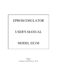
.
DCX NCAM2 TO EMC CONVERSION INSTRUCTIONS
This instruction sheet outlines the procedure required to convert an NCAM2 to the Event
Management and Concentration module. The conversion should only be carried out by a
competent engineer.
1. Check Package Contents
The conversion package should contain the following items. Ensure that all are present
before continuing
a)
EMC software EPROMS (8 ofil
XOOO-380426/X
3H
XOOO-380427/X
2H
XOOO-380428/X
lH
XOOO-380429/X
OH
XOOO-380430/X
3L
XOOO-380431/X
.
2 L
XOOO-380432/X
lL
XOOO-380433/X
OL
Where /x = the Issue number.
b) Latest User Manual text, part number X840-314051
c)
EMC module LED block label, part number X840-713303
If any of the above items are missing, contact your supplier.
2. Removing and Replacing the Software
WARNING: Full anti-static precautions must be strictly adhered to when removing and
replacing EPROMs.
The following should be undertaken, referring to Figure 1 for EPROM locations:
Remove NCAM EPROMS
XOOO-380111/X
XOOO-380112/X
XOOO-380113/X
XOOO-380114/X
XOOO-380115/X
XOOO-380116/X
XOOO-380117/X
XOOO-380118/X
3 H
2 H
::
3 L
2 L
::
Fit EMC EPROMS
X840-3 14751 Issue 1
-1-
Rev.O
p
Note: When removing the software EPROMs, ensure that no undue pressure is placed on
any other componentdlinks on the PCB. Install the new software on a rigid surface to
prevent flexing and possible damage of the PCB tracks which maybe caused by undue
pressure whilst inserting the EPROMs.
E
D
G
E
c
o
N
N
E
c
T
o
R
s
m
“m D
!
L
OL
c :z
:
:
I
9
CJ3CLI
—
02
—
Figure 2-1 Card Layout showing EPROM, Switches and Link Locations
3. Fitting the EMC LED Block Label
Remove the existing NCAM LED block label from the front panel by peeling it off from
the bottom upwards. You may find it necessary to carefully insert a sharp instrument
between the label and the panel to facilitate easier removal.
Peel off the backing paper from the new EMC LED block label and place this on the card
front panel.
4. Card Links and Switches
The options switches SW1 are not used on the EMC module and should be left in the
OPEN position.
The board links will not require alteration from the settings used on the NCAM2 and
should therefore be left unaltered.
6. Replacing the Module in the System
Once the above procedures have been carried out, the module is ready to be replaced in the
parent node. DO NOT replace the board into the node whilst power is applied, except in
the case of full specification DCX 870 nodes (i.e. those containing the System Module and
870 motherboard) with the MAPLOCK command initiated.
With the module replaced and power applied, the module is now ready for configuration.
.
Refer to Manual X840-314051 for configuration details.
X840-3 14751 Issue 1
-2-
Rev.O