1
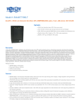
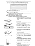
Table of Contents
English
Chapter 1: Safety Information..............................................................1
Handling Safety .....................................................................................1
Electrical Safety.....................................................................................1
Deenergizing Safety ..............................................................................1
Battery Safety ........................................................................................2
Replacement and Recycling of Batteries ...........................................2
Chapter 2: Basics....................................................................................3
About Your New UPS ...........................................................................3
Limited Warranty ..................................................................................3
How to Contact APC .............................................................................4
North America ...................................................................................4
Latin America ....................................................................................4
Chapter 3: Installing Your Smart-UPS................................................5
Unpacking..............................................................................................5
Inspection...........................................................................................5
Contents .............................................................................................5
Placement...........................................................................................5
How to Install Your Smart-UPS ............................................................5
Chapter 4: Operating Your Smart-UPS ............................................11
Indicators and Controls........................................................................11
Front Panel .......................................................................................11
Rear Panel ........................................................................................14
On-Battery Operation ..........................................................................15
How to Determine On-Battery Run Time ...........................................15
User Configuration Items ....................................................................16
Chapter 5: Maintenance and Troubleshooting..................................17
Storage.................................................................................................17
Storage Conditions...........................................................................17
Extended Storage .............................................................................17
Replacing the Battery ..........................................................................17
Battery Replacement Procedure.......................................................17
Troubleshooting...................................................................................19
Service .................................................................................................20
Appendix A: Specifications .................................................................21
Regulatory Agency Approvals ............................................................22
990-7097A, Revision 2 Feb 00
Appendix B: Transporting the UPS....................................................23
990-7097A, Revision 2 Feb 00
CHAPTER 1: SAFETY INFORMATION
This Safety Guide contains important instructions that should be followed during installation and
maintenance of the APC equipment and batteries. It is intended for APC customers who setup,
install, relocate, or maintain APC equipment.
Handling Safety
• Be careful. Do not lift heavy loads without assistance.
<18 kg (<40 lb.)
•
18 - 32 kg (40 - 70 lb.)
This equipment is intended for installation in a temperature-controlled indoor area (see
Appendix A: Specifications, page 21, for exact temperature range), free of conductive
contaminants.
Electrical Safety
•
To reduce the risk of fire, connect only to a circuit provided with a 20 Amp maximum branch
circuit overcurrent protection in accordance with the National Electrical Code ANSI/NFPA.
•
Do not work alone under hazardous conditions.
•
Check that the power cord(s), plug(s), and sockets are in good condition.
Deenergizing Safety
•
If the equipment has an internal energy source (the battery), the output may be energized
when the unit is not connected to an AC power outlet.
•
To deenergize pluggable equipment: first press the Off button for more than one second to
switch the equipment off. Next disconnect the equipment from the AC power outlet. Finally,
disconnect the battery.
•
Pluggable equipment includes a protective earth conductor which carries the leakage current
from the load devices (computer equipment). Total leakage current must not exceed 3.5 mA.
•
Use of this equipment in life support applications where failure of this equipment can
reasonably be expected to cause the failure of the life support equipment or to significantly
effect its safety or effectiveness is not recommended.
1
Battery Safety
•
This equipment contains potentially hazardous voltages. Do not attempt to disassemble the
unit. The only exception is for equipment containing batteries. Battery replacement using the
procedures below is permissible. Except for the battery, the unit contains no user serviceable
parts. Repairs are performed only by factory trained service personnel.
•
Do not dispose of batteries in a fire. The batteries may explode.
•
Do not open or mutilate batteries. They contain an electrolyte which is toxic and harmful to
the skin and eyes.
•
To avoid personal injury due to energy hazard, remove wrist watches and jewelry such as
rings when replacing the batteries. Use tools with insulated handles.
•
Replace batteries with the same number and type of batteries as originally installed in the
equipment.
Replacement and Recycling of Batteries
See your dealer or Replacing the Battery, page 17, for information on replacement battery kits and
battery recycling.
2
CHAPTER 2: BASICS
About Your New UPS
This APC Uninterruptible Power Supply (UPS) is designed to prevent blackouts, brownouts, sags
and surges from reaching your computer and other valuable electronic equipment. This UPS also
filters out small utility line fluctuations and isolates your equipment from large disturbances by
internally disconnecting from the utility line, while supplying power from its internal batteries
until the utility line returns to safe levels.
The UPS is ready to be mounted in a 19-inch wide EIA/IEC rack cabinet.
Limited Warranty
American Power Conversion (APC) warrants its products to be free from defects in materials and
workmanship for a period of two years from the date of purchase. Its obligation under this
warranty is limited to repairing or replacing, at its own sole option, any such defective products.
To obtain service under warranty you must obtain a Returned Material Authorization (RMA)
number from customer support (see Service, page 20). Products must be returned with
transportation charges prepaid and must be accompanied by a brief description of the problem
encountered and proof of date and place of purchase. This warranty does not apply to equipment
which has been damaged by accident, negligence, or misapplication or has been altered or
modified in any way. This warranty applies only to the original purchaser who must have
properly registered the product within 10 days of purchase.
EXCEPT AS PROVIDED HEREIN, AMERICAN POWER CONVERSION MAKES NO
WARRANTIES, EXPRESSED OR IMPLIED, INCLUDING WARRANTIES OF
MERCHANTABILITY AND FITNESS FOR A PARTICULAR PURPOSE. Some states do not
permit limitation or exclusion of implied warranties; therefore, the aforesaid limitation(s) or
exclusion(s) may not apply to the purchaser.
EXCEPT AS PROVIDED ABOVE, IN NO EVENT WILL APC BE LIABLE FOR DIRECT,
INDIRECT, SPECIAL, INCIDENTAL, OR CONSEQUENTIAL DAMAGES ARISING OUT OF
THE USE OF THIS PRODUCT, EVEN IF ADVISED OF THE POSSIBILITY OF SUCH
DAMAGE. Specifically, APC is not liable for any costs, such as lost profits or revenue, loss of
equipment, loss of use of equipment, loss of software, loss of data, costs of substitutes, claims by
third parties, or otherwise.
3
How to Contact APC
Internet: http://www.apcc.com
North America
Phone ............................... 1.800.800.4272
Fax ................................... 1.401.788.2743
Email ............................... [email protected]
Latin America
Argentina ......................... 0800.9.APCC (0800.9.2722)
Brazil ............................... 0800.12.72.21
Colombia ......................... 980.15.39.47
Mexico............................. 95.800.804.4283
Uruguay ........................... 000.413.598.2139
Venezuela ........................ 8001.2856
Email ............................... [email protected]
4
CHAPTER 3: INSTALLING YOUR SMART-UPS
Unpacking
APC has taken care to design robust packaging for your product. However, accidents and damage
may occur during shipment.
Inspection
Inspect the UPS upon receipt. Notify the carrier and dealer if there is damage. The packaging is
recyclable; save it for reuse or dispose of it properly.
Contents
The shipping package contains the UPS, its front panel bezel (disconnected from the unit), 1U
mounting rails, and a literature kit (containing software, mounting hardware, two serial cables, and
product documentation).
Placement
S
m
a
r
t
-
U
P
S
S
m
a
r
t
-
U
P
S
S
m
a
r
t
-
U
P
Install the UPS in a protected area that is free of
excessive dust and has adequate air flow. Do not
operate the UPS where the temperature and
humidity are outside the specified limits.
S
Changes or modifications to this unit not expressly approved by the party
responsible for compliance could void the warranty.
How to Install Your Smart-UPS
To install the UPS follow these five steps:
1. Mount the UPS in the rack.
2.
Connect the battery and attach the front panel bezel.
3.
Connect power and the equipment to the UPS.
4.
Turn on the UPS.
5. Install PowerChute® software (optional) and accessories.
This section describes each step in detail.
Install the UPS in the Rack
The UPS requires two people to install due to its weight.
To lighten the UPS, you may remove the batteries while you mount the unit in the rack.
Refer to Replacing the Battery, page 17, for instructions on removing the batteries.
5
Please observe the following guidelines when installing the UPS:
•
The UPS comes with standard 19” (46.5 cm) rack mount brackets (ears) installed.
•
The UPS can be mounted in either a 2-post or 4-post rack. You may need to reposition the
rack mount brackets for some installations, such as a 2-post rack installation. The rack can
have any of the common types of equipment mounting holes (square, round-threaded, or
round-non-threaded). All necessary hardware is provided.
•
Two additional sets of bracket holes, shown in the following figure, are located on the sides of
the UPS. These holes allow you to mount the brackets with a 1.4 inch or 5 inch setback.
Move the rack mount brackets back, if desired, to optimize the esthetic or physical
requirements of the rack.
Where
•
Note: Left mounting bracket removed for clarity.
= Standard ear mounting location
= Optional (1.4 inch setback) ear mounting location
= 2-post rack (5 inch setback) ear mounting location
Optional 24” rack mount brackets are available (part number SU026-2U).
• Mounting rails are included. The rails support the UPS and allow adequate air flow.
Mount the UPS in the Rack
• The mounting rails are designed to fit a four-post rack. If you are using a two-post
rack, use the mounting brackets alone to mount the UPS.
• If you are using a two-post rack, you should reposition the mounting brackets to the
5” setback position before mounting the UPS in your rack.
• Due to the weight of the UPS, two people are required to mount the UPS in a rack.
Check the rack to make sure it will not tip after moving the UPS mounting
brackets.
6
1.
Select a location for the UPS in your rack. Mount the UPS at or near the bottom of the rack.
The UPS occupies a space of 2U. Some racks have tick marks to indicate the U-spaces.
• UPSs are heavy. Select a rack location sturdy enough to handle the weight.
• Select a rack location with adequate air flow that is free from excessive dust. Ensure that
the air vents on the sides of the UPS are not blocked. Do not operate the UPS where
temperature or humidity are outside the limits listed in Appendix A: Specifications,
page 21.
2.
Use the nut plate provided (part number 870-1148) to identify the correct holes where the
mounting bracket will attach. The top and bottom holes on the nut plate align with the top
and bottom holes on the mounting brackets.
For racks with square holes: Use the square button to locate the mounting position.
For racks with round holes: Use the round button to locate the mounting position.
Round Hole Rack
Nut Plate
Rack Post
Flat Head Screw
8-32 X 5/8
long
3.
Use round
button to
locate mounting
position.
Hex Nut
8-32
Rack Post
Cup Washer
Flat Head Screw
8-32 X 5/8
long
Nut Plate
Hex Nut
8-32
Use square
button to
locate mounting
position.
Locate the 1U mounting rails and remove the slide screw and nut, shown at . Leave the
front and rear segments, assembled.
4.
Square Hole Rack
The sides of the UPS have two holes at the rear of the unit. Align the top two holes on the
front rail segment , with the two holes at the rear of the UPS and secure them with the flat
head screws (#8 x ¼”), provided.
Two people are required to complete this step due to the weight of the UPS.
7
5.
Support the UPS from the bottom or rear of the unit and slide it into the rack.
6.
Secure the UPS into position by inserting two ornamental (10-32) screws through the front of
the mounting bracket on each side. The screws will thread into the nut plate.
7.
From the rear of the rack, extend the rear rail segment to the rear rack post. Use the (flat head
screws #10 x ½”) and cup washers provided, to attach the rail to the rack post.
8.
Insert and tighten the slide screws and nuts to secure the front and rear rail segments.
Removing the UPS from the Rack
1.
Remove the front panel bezel: Face the front of the UPS, and, using both hands, insert each
index finger behind the lip of the curved section of the front panel bezel and pull towards you.
2.
From the rear of the rack, remove the slide screws and nuts that connect the rails segments.
3.
Support the UPS from the bottom or rear of the unit.
4.
Grasp the battery tray handle to support the front of the unit.
5.
Unscrew the four ornamental screws (two screws on each mounting bracket).
6.
Slide the UPS out of the rack.
8
Connect the Battery and Attach the Front Panel Bezel
The UPS is shipped without its battery connected and the front panel bezel installed (it
is packaged separately within the main box). You must connect the battery and install
the plastic front panel bezel before the installation is complete.
1.
Facing the front of the UPS, locate the battery cable (in the center of the unit) and remove the
tape to expose the cable connector.
2.
Locate the UPS battery connector which is to the right of the battery tray and recessed.
Connect the battery cable connector to the UPS connector. Press firmly to ensure that the
connection is tight. You will hear a “snap” when the connector is properly seated. Also, as a
visual indication, the back of the connector should be recessed (~0.25 in.) from the sheet
metal on the front of the unit. You may see small sparks when connecting the battery.
3.
Tuck the white battery cable cord into the space above the UPS connector.
4.
Unpack the front panel bezel and hold it with the cutout section on the right. Align the tabs
on the side of the bezel with the slots on the front of the UPS and firmly snap it into place.
Connect Power and Equipment to the UPS
Use an APC supplied cable to connect to the Computer Interface Port. DO NOT
use a standard serial interface cable since it is incompatible with the UPS
connector.
The UPS package contains two serial cables. Refer to the Software Installation
Instruction Sheet, included with the UPS, to determine which serial cable to use.
•
Plug the UPS into a standard receptacle.
•
Plug the equipment into the back of the UPS.
•
Do not plug laser printers into a UPS of 1000 VA or less, due to the large increase in power
consumption when printing.
•
Turn on all connected equipment (the equipment will not be powered until the UPS is turned
on).
•
Add accessories for the SmartSlot. See the literature accompanying the accessory for details.
9
•
Connect ground leads to the TVSS screw (optional). The transient voltage surge suppression
(TVSS) screw provides grounding through the UPS’s power cord ground conductor. See
Rear Panel, page 14, for the location of the screw. To make the connection, loosen the screw
and connect the surge suppression device’s ground lead. Tighten the screw to secure the lead.
•
Check the site wiring fault indicator (located on the rear panel, see Rear Panel, page 14). It
lights up if the UPS is plugged into an imp, page roperly wired AC power outlet. Wiring
faults detected include missing ground, hot-neutral polarity reversal, and overloaded neutral
circui
If the UPS indicates a site wiring fault, get a qualified electrician to correct the
building wiring.
Turn on the UPS
Make sure the battery is connected before turning on the UPS!
•
|
Press the UPS’s on
button, located on the front panel, to power-up your UPS. This will
power-up connected equipment.
T E S T
The UPS charges its battery whenever it is connected to utility power. The battery
charges fully during the first four hours of normal operation. Do not expect full run
time during this initial charge period.
•
The unit performs a self-test automatically when turned on, and every two weeks thereafter
(by default).
Install PowerChute Software (Optional) and Accessories
For additional computer system security, install PowerChute UPS monitoring software. It
provides automatic unattended shutdown capabilities on most major network operating systems.
See the Software Installation Instruction Sheet, included with the UPS, for details.
This UPS is equipped with a SmartSlot for accessories. See the APC website
(apcc.com) for available accessories.
If a standard accessory is installed on this UPS, follow the installation instructions for
the accessory, which are included in the package.
10
CHAPTER 4: OPERATING YOUR SMART-UPS
Indicators and Controls
This rack mount UPS has the power control and operating indicators located on the front panel.
The rear panel has the input and output connectors.
Front Panel
|
TEST
0
Switch On – Switch Off
|
T E S T
0
To turn the UPS on: With the UPS plugged in, press and release the large, upper button labeled
“l TEST” to supply power to the connected equipment. The equipment is immediately powered
while the UPS performs a self-test.
To turn the UPS off: Press and release the small, lower button labeled “0” to turn off power to the
connected equipment. It may be convenient to use the UPS as a master on/off switch for the
connected equipment.
Whenever the UPS is plugged in and utility voltage is present, the charger maintains
battery charge.
On-line Indicator
The on-line indicator illuminates when the UPS is supplying utility power to the connected
equipment.
85%
67%
50%
33%
17%
Load Bar Graph
The 5-LED display on the left of the front panel represents the power drawn from the UPS as a
percentage of total capacity. For example, if three LEDs are lit, the load (connected equipment) is
drawing between 50% and 67% of the UPS’s capacity. If all five LEDs light, thoroughly test your
complete system to make sure that the UPS will not become overloaded. In the graphic to the left,
the load capacity threshold is listed next to the LED (these are not shown on the actual UPS).
On-Battery Indicator
During on-battery operation, the on-battery LED illuminates and the UPS sounds an audible alarm
consisting of four beeps every 30 seconds. The alarm stops when the UPS returns to on-line
operation. Refer to On-Battery Operation, page 15, for details.
11
Battery Charge Bar Graph
96%
72%
48%
24%
0%
The 5-LED display on the right of the front panel shows the present charge of the UPS’s battery as
a percentage of the battery’s capacity. When all five LEDs are lit, the battery is fully charged.
The LEDs extinguish, from top to bottom, as the battery capacity diminishes. The battery
capacity threshold is shown in the figure to the left (it is not listed on the front panel display).
As a low battery warning, any LEDs illuminated (for the given capacity) will flash. The low
battery warning setting can be changed from the rear panel (see Low Battery Warning Level, page
14) or through the optional PowerChute software.
Overload
When the UPS is overloaded (when the connected equipment exceeds the maximum specified in
the “maximum load,” section in Appendix A: Specifications, page 21), the overload LED comes
on and the UPS emits a sustained tone. The alarm remains on until the overload is removed. The
UPS continues to supply power as long as it is on line and the breaker does not trip, but it will not
provide power from batteries in the event of a utility voltage interruption. Disconnect nonessential
equipment from the UPS to eliminate the overload. If a continuous overload occurs while the UPS
is on battery, the UPS will turn off its output in order to protect itself from possible damage.
Self-Test
The UPS performs a self-test automatically when turned on, and every two weeks thereafter (by
default). Automatic self-test eases maintenance requirements by eliminating the need for periodic
manual self-tests. During the self-test, the UPS briefly operates the connected equipment onbattery. If the UPS passes the self-test, it returns to on-line operation.
If the UPS fails the self-test it immediately returns to on-line operation and lights the replace
battery LED. The connected equipment is not affected by a failed test. Recharge the battery for
24 hours and perform another self-test. If it fails, the battery must be replaced. See Replacing the
Battery, page 17, for details.
How to Manually Initiate a Self-Test
Press and hold the on button (on the front panel) for a few seconds before the self-test will begin.
Replace Battery
If the battery fails a self-test, the UPS emits short beeps for one minute and the replace battery
LED illuminates. (If the LED flashes, the battery is disconnected.) The UPS repeats the alarm
every five hours. Perform the self-test procedure after the battery has charged for 24 hours to
confirm the replace battery condition. The alarm will stop if the battery passes the self-test.
Voltage Trim
The voltage trim LED comes on to indicate that the UPS is compensating for a high utility voltage.
Voltage Boost
The voltage boost LED comes on to indicate that the UPS is compensating for a low utility voltage.
12
Low Battery
When the UPS is operating on-battery and the energy reserve of the battery runs low, the UPS
beeps continuously (by default) until the UPS shuts down from battery exhaustion or returns to online operation. The low battery warning interval can be changed through software.
Cold Start
When the UPS is off and there is no utility power, use the cold start feature to apply power to the
connected equipment from the UPS’s battery. Cold start is not a normal condition.
133
124
114
105
96
•
Press and hold the on button until the UPS beeps.
•
Release the on button during the beep and the connected equipment is powered.
Utility Voltage Bar Graph
This UPS has a diagnostic feature that displays the utility voltage. With the UPS plugged into the
normal utility power, press and hold the on button to see the utility voltage bar graph display.
After a few seconds the 5-LED display on the right of the front panel shows the utility input
voltage. Refer to the figure to the left for the voltage reading (values are not listed on the UPS).
The display indicates that the voltage is between the displayed value from the list and the next
higher value. For example, with three LEDs lit, the input voltage is between 114 and 124 VAC.
If no LEDs come on and the UPS is plugged into a working AC power outlet, the line voltage is
extremely low.
If all five LEDs come on, the line voltage is extremely high and should be checked by an
electrician.
The UPS starts a self-test as part of this procedure. The self-test does not affect the
voltage display.
Shutdown Mode (via software or an accessory)
In shutdown mode the UPS stops supplying power to the connected equipment, waiting for the
return of utility power. If there is no utility power present, external devices (e.g., servers)
connected to the computer interface or the accessory slot can command the UPS to shut down.
This is normally done to preserve battery capacity after the graceful shutdown of protected
servers. The UPS will scroll the front panel indicators sequentially in shutdown mode.
13
Rear Panel
x
M AD E I N U S A (W ES T K IN GS TON , R I )
S U 1400R M2U
X X01234 56789
Computer Interface Port
Power management software and interface kits can be used with this UPS. Use only interface kits
supplied or approved by APC. If used, connect the interface cable to the 9-pin computer interface port on the back panel of the UPS. Secure the connector’s screws to complete the connection.
TVSS Screw
The UPS features a transient voltage surge-suppression (TVSS) screw for connecting the ground
lead on surge suppression devices, such as telephone and network line protectors. Refer to
Connect Power and Equipment to the UPS, page 9, for information.
Voltage Sensitivity
The UPS detects line voltage distortions such as spikes, notches, dips, and swells, as well as
distortions caused by operation with inexpensive fuel-powered generators. By default, the UPS
reacts to distortions by transferring to on-battery operation to protect the connected equipment.
Where power quality is poor, the UPS may frequently transfer to on-battery operation. If the
connected equipment can operate normally under such conditions, battery capacity and service life
may be conserved by reducing the sensitivity of the UPS.
To reduce UPS sensitivity, press the Sensitivity button on the rear panel. Use a pointed object
such as a pen to press the button. Press it once to set the UPS’s sensitivity to reduced. Press it
again to set the sensitivity to low. Press the button a third time to reset normal sensitivity. The
Sensitivity can also be changed through software.
normal
reduced
low
When the UPS is set to normal sensitivity, the LED is brightly lit.
When it is set to reduced sensitivity, the LED is dimly lit.
When it is set to low sensitivity, the LED is off.
Low Battery Warning Level
By default, the low battery warning occurs when there are approximately two minutes of
on-battery run time remaining. This may not be enough time to gracefully shut down some
protected computer systems.
To change the warning interval, press the rear panel Sensitivity button while pressing and holding
the front-panel on button.
2 min.
When the LED is brightly lit, the low battery warning interval is approximately two minutes.
5 min.
When the LED is dimly lit, the low battery warning interval is approximately five minutes.
7 min.
When the LED is off, the low battery warning interval is approximately seven minutes.
14
Site Wiring Fault Indicator
This indicator lights up when the UPS is connected to an improperly wired AC power outlet.
On-Battery Operation
The Smart-UPS will switch to battery operation automatically should the utility power fail. While
running on battery, an internal alarm will sound (periodic beeps). Press the on button, on the front
panel, to silence the UPS alarm (for the current alarm only). The PowerChute software allows you
to change the audible indicator.
If the utility power does not return, the UPS will continue supplying power to the connected
equipment until exhausted. A continuous beeping will sound approximately two minutes before
the UPS’s final low battery shutdown. If using a computer, you must manually save your files and
power down before the UPS turns itself off, unless you are using PowerChute interface software
that provides automatic, unattended shutdown.
How to Determine On-Battery Run Time
UPS battery life differs based on usage and environment.
On-Battery Run Time (Minutes)
Load (VA)
50
100
200
300
400
500
600
700
800
900
1000
1200
1400
Load (watts)
30
60
122
185
249
315
382
450
522
595
670
809
950
SU700
142
76
37
23
16
12
10
8.0
–
–
–
–
–
15
SU1000
224
127
64
41
29
23
18
15
12
11
9.2
–
–
SU1400
269
157
80
51
37
28
22
18
15
13
11
9.0
7.4
User Configuration Items
Note: Setting these items requires software or optional hardware.
Function
Factory
Default
User Selectable
Choices
Description
Automatic SelfTest
Every 14
days
(336 hours)
Every 7 days (168
hours), On Startup
Only, No Self-Test
Sets the interval at which the UPS will execute
a self-test. Refer to your software manual for
details.
UPS ID
UPS_IDEN
Up to eight
characters to define
the UPS.
Use this field to uniquely identify the UPS for
network management purposes.
Date of Last
Battery
Replacement
Manufacture
Date
Date of Battery
Replacement
Reset this date when you replace the battery
tray.
Minimum
Capacity Before
Return from
Shutdown
Sensitivity
0 percent
15, 25, 35, 50, 60,
75, 90 percent
The UPS will charge its batteries to the
specified percentage before return from a
shutdown.
Normal
Reduced, Low
Duration of Low
Battery Warning
2 minutes
5, 7, 10, 12, 15, 18,
20 minutes
Alarm Delay
After Line Fail
5 second
delay
Shutdown Delay
20 seconds
Synchronized
Turn-on Delay
0 seconds
High Transfer
Point
127 VAC
30 second delay,
At Low Battery
Condition, No
0, 60, 120, 240,
480, 720, 960
seconds
20, 60, 120, 240,
480, 720, 960
seconds
130, 133, 136 VAC
Set lower than normal sensitivity to avoid
lowered battery capacity and service life in
situations where the connected equipment can
tolerate minor power disturbances.
Sets the time before shutdown at which the
UPS issues a low battery warning. Set it
higher than the default if the OS needs more
time for a graceful shutdown.
To avoid alarms for minor power glitches, set
the alarm delay.
Low Transfer
Point
106 VAC
103, 100, 97 VAC
16
Sets the interval between when the UPS
receives a shutdown command and when
shutdown occurs.
The UPS will wait the specified time after the
return of utility power before turn-on; for
example, to avoid branch circuit overload.
To avoid unnecessary battery usage, set the
High Transfer Point higher if the utility voltage
is chronically high and the connected
equipment is known to work under this
condition.
Set the Low Transfer Point lower if the utility
voltage is chronically low and the connected
equipment can tolerate this condition.
CHAPTER 5: MAINTENANCE AND TROUBLESHOOTING
Storage
Storage Conditions
Store the UPS covered and flat (rack mount orientation) in a cool, dry location, with its battery
fully charged. Disconnect any cables connected to the computer interface port to avoid
unnecessarily draining the battery. See Removing the UPS from the Rack, page 7, for
instructions.
Extended Storage
At -15 to +30 °C (+5 to +86 °F), charge the UPS’s battery every six months.
At +30 to +45 °C (+86 to +113 °F), charge the UPS’s battery every three months.
Replacing the Battery
This UPS has an easy to replace hot-swappable battery tray. Battery replacement is a safe
procedure, isolated from electrical hazards. You may leave the UPS and the protected equipment
on for the following procedure. See your dealer or APC (refer to How to Contact APC, page 4)
for information on replacement battery cartridges.
Smart-UPS Model
Replacement Battery Cartridge
SU700RM2U
RBC22
SU1000RM2U
RBC23
SU1400RM2U
RBC24
Please read Chapter 1: Safety Information, page 1, before replacing the battery tray.
Once the battery is disconnected, the connected equipment is not protected from power
outages.
Battery Replacement Procedure
1.
2.
3.
4.
The battery tray is accessible from the front of the UPS.
Be careful removing the battery tray – it is heavy.
This procedure requires a Phillips head screwdriver.
Small sparks at the battery connectors are normal during re-connection.
17
1. Face the front of the UPS and, using both hands, insert each
index finger behind the lip of the curved section of the front
panel bezel and pull towards you. The front panel bezel will
unsnap.
2. Set the bezel aside.
3. Take out the white cord, which is tucked into the space above
the battery connector . Grasp the cord and pull firmly
towards you to disconnect the battery.
4. Use a Phillips head screwdriver to remove the four (4)
screws that secure the battery tray. Set the screws aside.
5. Use the battery tray handle to slide the tray out halfway.
Then hold the tray from the sides and slide it out to the
maximum extended position. A stop tab on the bottom of
the tray will prevent the tray from coming out completely.
6. Carefully lift the tray up so that the stop tab clears the
ledge on the unit.
7. Return the battery tray to APC using the package in which
your replacement tray shipped . (See How to Contact APC,
page 4, for details.) The battery replacement kit includes a
new battery tray.
8. Hold the new tray on the sides and align it with the opening.
9. Raise the back of the tray up slightly to position the stop tab
on the inside of the opening. Then level the tray and push it
in completely.
10.Remove the tape on the new battery tray connector to expose
the cable connector.
11. Locate the UPS battery connector which is to the right of
the battery tray and recessed. Connect the battery cable
connector to the UPS connector. Press firmly to ensure that
the connection is tight. You will hear a “snap” when the
connector is properly seated.
12.Replace the four (4) screws removed in step 4.
13.Tuck the white battery cable cord neatly into the space above
the UPS connector.
14.Hold the front panel bezel with the cutout section on the
right. Align the tabs on the side of the bezel with the slots on
the front of the UPS and firmly snap it into place.
18
Troubleshooting
Use the chart below to solve minor UPS installation problems. Contact APC Technical Support
Staff (see How to Contact APC, page 4) for assistance with complex UPS problems.
Problem and Possible Cause
UPS will not turn on.
• ON button not pushed.
• UPS not connected to AC power
supply.
• UPS’s input circuit breaker tripped.
• Very low or no utility voltage.
• Battery not connected properly.
UPS will not turn off.
• Internal UPS fault.
Solution
Press the ON button once to power the UPS and the connected
equipment.
Check that the power cable from the UPS to the utility power
supply is securely connected at both ends.
Reduce the load on the UPS by unplugging equipment and reset
the circuit breaker (on back of UPS) by pressing the plunger
back in.
Check the AC power supply to the UPS with a table lamp. If
very dim, have the utility voltage checked.
Check that the battery connector is fully engaged.
Do not attempt to use the UPS. Unplug the UPS and have it
serviced immediately.
UPS operates on-battery although normal line voltage exists.
Reduce the load on the UPS by unplugging equipment and reset
• UPS’s input circuit breaker tripped.
the circuit breaker (on back of UPS) by pressing the plunger
back in.
Move the UPS to a different outlet on a different circuit. Test
• Very high, low, or distorted line
the input voltage with the utility voltage display. If acceptable
voltage. Inexpensive fuel powered
to the connected equipment, reduce the UPS’s sensitivity. See
generators can distort the voltage.
Voltage Sensitivity, page 14, for procedures.
UPS beeps occasionally.
None. The UPS is protecting the connected equipment.
• Normal UPS operation.
UPS does not provide expected backup time.
Charge the battery. Batteries require recharging after extended
• The UPS’s battery is weak due to a
outages. Also, they wear faster when put into service often or
recent outage or is near the end of
when operated at elevated temperatures. If the battery is near
its service life.
the end of its service life, consider replacing the battery even if
the replace battery indicator is not yet lit.
Check the UPS’s load bar display. Unplug less needed
• The UPS is overloaded.
equipment, such as printers.
Front panel indicators (the six in the center) light sequentially.
None. The UPS will restart automatically when utility power
• The UPS has been shut down by
returns. The indicators illuminate from top to bottom then
remote control.
bottom to top.
None. The UPS will restart automatically when the sleep timer
• The UPS has been put into sleep
expires. The indicators illuminate from top to bottom then back
mode by remote control.
to the top.
19
Some or all front panel indicators are flashing.
• Internal UPS fault or battery charger Do not attempt to use the UPS. Turn the UPS off and have it
serviced immediately.
failure.
UPS is plugged into wall outlet and only the battery charge bar graph is lit.
None. The UPS will return to normal operation when the power
• The UPS is shut down and the
is restored and the battery has a sufficient charge.
battery is discharged from an
extended outage.
Replace battery light is lit and the UPS beeps for one minute every five hours.
Charge the batteries for 24 hours and perform self-test (see Self• Weak batteries.
Test, page 12) to see if it clears.
Replace the batteries. Refer to Replacing the Battery, page 17.
• Bad or expired battery.
Replace battery light flashes, battery charge bar graph is off, and the UPS beeps continuously.
Check that the battery connector is fully engaged.
• Battery not connected properly.
Site wiring fault indicator is lit; UPS operates normally.
Have qualified electrician correct the building wiring.
• Building wire error.
Service
If the UPS requires service do not return it to the dealer! Follow these steps:
1. Review the problems discussed in Troubleshooting, page 19, to eliminate common problems.
2.
Verify that no circuit breakers are tripped – this is the most common UPS problem!
3.
If the problem persists, call customer service, refer to How to Contact APC, page 4, or visit
the APC Internet website (www.apcc.com).
•
4.
Note the model number of the UPS, the serial number, and the date purchased. A
technician will ask you to describe the problem and try to solve it over the phone, if
possible. If this is not possible the technician will issue a Returned Material
Authorization Number (RMA#).
• If the UPS is under warranty, repairs are free. If not, there is a repair charge.
Pack the UPS in its original packaging. If the original packing is not available, ask customer
service about obtaining a new set.
•
Pack the UPS properly to avoid damage in transit. Never use Styrofoam beads for
packaging. Damage sustained in transit is not covered under warranty.
•
Include a letter with your name, RMA#, address, copy of the sales receipt, description of
the trouble, your daytime phone number, and a check (if necessary).
5.
Mark the RMA# on the outside of the package.
6.
Return the UPS by insured, prepaid carrier to the address given to you by Customer Service.
20
APPENDIX A: SPECIFICATIONS
700 VA
Acceptable input voltage
On-line input voltage range1
(configured via software)
Output voltage
(configured via software)
Input Protection
Frequency limits
(on-line operation)
Transfer time
Maximum load
On-battery output voltage
On-battery frequency
On-battery waveshape
Protection
Noise Filter
Battery type
Typical battery life
Typical recharge time
Operating temperature
Storage temperature
Operating and storage
relative humidity
Operating elevation
Storage elevation
Electromagnetic immunity
Audible noise in dBA at 1 m
(3 ft)
Size (H x W x D)
Weight - net (shipping)
Safety approvals
EMI verification
1
1000 VA
0 – 160 VAC
1400 VA
82 − 144 V
106 – 127 VAC
Resettable circuit breaker
47 – 63 Hz
2 ms typical, 4 ms maximum
450 W
670 W
950 W
115 VAC
50 or 60 Hz, ±0.1 Hz; unless synchronized to utility during brownout
Sine wave
Overcurrent and short-circuit protected, latching shutdown on overload
Normal and common mode EMI/RFI suppression
Spill proof, maintenance free, sealed lead-acid
3-6 years, depending on number of discharge cycles and
ambient temperature
3 hours
0 to +40 ºC (+32 to +104 ºF)
-15 to +45 ºC (+5 to +113 ºF)
0 to 95%, non-condensing
0 to +3,000 m (0 to +10,000 ft)
0 to +15,000 m (0 to +50,000 ft)
IEC 801-2 level IV, 801-3 level III, 801-4 level IV, 801-5
<35.4
<34.9
<46.0
3.36 in (ear ht 3.42 in) x 17 in (ear to ear 18.9 in) x 18 in
8.53 cm (ear ht 8.70 cm) x 43.2 cm (ear to ear 48.0 cm) x 45.7 cm
21.8 (25.1) kg
28.1 (31.4) kg
28.6 (31.9) kg
48 (55.25) lbs.
62 (69.25) lbs.
63 (70.25) lbs.
Listed to UL 1778, certified to CSA 107.1
FCC/DOC Class A certified
If the load is ≥86% of capacity, the on-line input voltage is 93 − 144 V.
21
Regulatory Agency Approvals
®
LISTED 42C2
E95463
LR63938
22
APPENDIX B: TRANSPORTING THE UPS
Follow these guidelines if you need to ship the UPS to another location. These guidelines apply
whether you are transporting the UPS alone, rack mounted in an equipment cabinet, or installed in
a system.
Always DISCONNECT THE BATTERIES before shipping the UPS to avoid
damage during transport. (U.S. Federal Regulation requires that batteries be
disconnected during shipment.) The batteries may remain in the UPS; they do
not have to be removed.
This requirement applies whether the UPS is moved indoors or out, alone or
installed in an equipment rack or system.
Graphics are not drawn to scale. They are shown for reference only.
The battery compartment is located under the front panel bezel.
1.
2.
3.
Face the front of the UPS and, using both hands, insert
each index finger behind the lip of the curved section of
the front panel bezel and pull towards you. The front
panel bezel will unsnap.
Set the bezel aside.
Take out the white cord, which is tucked into the space
above the battery connector . Grasp the cord and pull
firmly towards you to disconnect the battery.
Remember to connect the batteries once the UPS has arrived at its destination.
23
NOTES