1
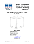
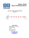
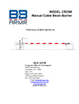
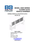
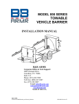
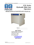
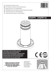
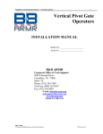
MODEL B3X SERIES SEMI-AUTOMATIC INSTALLATION AND OPERATIONS MANUAL B&B ARMR CORPORATE OFFICE & TECHNICAL SUPPORT 2009 CHENAULT DRIVE CARROLLTON, TX 75006 SUITE 114 PHONE: (800) 367-0387 FAX: (972) 385-9887 E-mail: [email protected] [email protected] MADE IN THE USA Installation and Operations Manual — Model B-3X Series Your safety is extremely important to us. If you have any questions or are in doubt about any aspect of the equipment, please contact us. INTRODUCTION Welcome! Congratulations on your purchase of a B&B ARMR vehicle barrier. In addition to providing detailed operating instructions, this manual describes how to install, maintain, and troubleshoot your vehicle barrier. If you require additional assistance with any aspect of your vehicle barrier's installation or operation, please contact us. With years of experience in all aspects of perimeter security and related disciplines, our products are used throughout the world to control access and to protect people, equipment, and facilities. We offer a broad range of vehicle barrier and related security services: Turnkey installations Routine barrier preventative maintenance or emergency repairs (including work on non-B&B ARMR products) Spare or replacement parts Custom designs or special installations Equipment upgrades (modernize your old equipment with state-of-the-art hydraulics and control systems) Ancillary security equipment such as security guard enclosures, card readers, security lighting, and many other security related products. Technical support via telephone and possible on site support with advanced scheduling. Safety © 2013 B&B ARMR A Division of B&B Roadway Security Solutions B30SA-9001 E Feb-13 Installation and Operations Manual — Model B-3X Series SYMBOL MEANING: The lightning flash with arrowhead symbol, within an equilateral triangle, is intended to alert the user to the presence of non-insulated "dangerous voltage" within the product's enclosure that may be of sufficient magnitude to constitute a risk of electric shock to persons. The exclamation point within an equilateral triangle is intended to alert the user to the presence of important operating and maintenance (servicing) instruction in the literature accompanying the product. B&B ARMR does not assume responsibility for injury to persons or property during installation, operation, or maintenance. As the user, you are responsible for correct and safe installation, operation, and maintenance of this equipment. Users must follow the specific instructions and safety precautions located in this manual. B&B encourages customers to follow the safety standards of the Occupational Safety and Health Administration (OSHA), as well as other applicable federal, state, and local safety regulations and industry standards and procedures. For installation outside the United States, follow applicable international, regional, and local safety standards. Engage only trained and experienced staff to install, operate, and maintain the equipment and ensure that all repairs are performed correctly, using properly trained technicians and the correct tools and equipment. Additional safety devices may be included with this barrier system: o Vehicle loop detector(s) – Safety loop o Traffic arms and lights o IR beams and Safety edges How to Contact Us B&B ARMR works with an extensive list of value added resellers to best support our customers. Our resellers offer not only our superior products, but provide excellent support. If you should need advanced assistance with your vehicle barrier or would like further information on any physical security applications please contact us at: Corporate/Tech Support: Field Service Office: B&B ARMR B&B ARMR 2009 Chenault Drive Suite 114 8451 Hilltop Rd Suite L Carrollton, TX 75006 USA Fairfax, VA 22030 Telephone: (972) 385-7899 (703)663-8711 Toll Free: (800) 367-0387 Fax: (972) 385-9887 E-mail: [email protected] [email protected] © 2013 B&B ARMR A Division of B&B Roadway Security Solutions B30SA-9001 E Feb-13 Installation and Operations Manual — Model B-3X Series Table of Contents INTRODUCTION........................................................................................................ii Safety ..............................................................................................................................ii How to Contact Us ...................................................................................................... iii 1 ORIENTATION ...................................................................................................5 1.1 Overview...................................................................................................................................... 5 1.1.1 Cylinder Weldment Assembly................................................................................................ 6 1.1.2 Tube Cover Plate .................................................................................................................... 6 1.1.3 Gas Shock ............................................................................................................................... 6 1.1.4 Housing Weldment ................................................................................................................. 6 1.1.5 Collision Pins.......................................................................................................................... 6 1.1.6 Cover Plate ............................................................................................................................. 6 1.1.7 Guide Strip.............................................................................................................................. 6 1.1.8 Options ................................................................................................................................... 7 2 3 4 5 INSTALLATION ..................................................................................................7 2.1 Introduction ................................................................................................................................. 7 2.2 Environmental Conditions........................................................................................................... 7 2.3 Site Preparation .......................................................................................................................... 7 2.4 Positioning .................................................................................................................................. 9 2.5 Rebar and Conduit Installation ................................................................................................... 9 2.6 Concrete .................................................................................................................................... 10 2.7 Optional Pad Heater or Heater Strip ........................................................................................ 10 2.8 Final Pre-operation Checklist ................................................................................................... 10 OPERATION .......................................................................................................11 3.1 Introduction ............................................................................................................................... 11 3.2 Control ...................................................................................................................................... 11 MAINTENANCE ................................................................................................11 4.1 Introduction ............................................................................................................................... 12 4.2 Spare Parts ................................................................................................................................ 12 4.3 Bi-Monthly Inspections.............................................................................................................. 12 TROUBLESHOOTING ..................................................................................... 13 5.1 B3X Troubleshooting Guide ...................................................................................................... 13 6 WARRANTY........................................................................................................ 14 7 APPENDIX.......................................................................................................... 15 7.1 Equipment Maintenance Log Form ........................................................................................... 15 © 2013 B&B ARMR A Division of B&B Roadway Security Solutions B30SA-9001 E Feb-13 1 ORIENTATION 1.1 Overview The model B3X Hydraulic Bollard system is designed to act as a vehicular deterrent for perimeter security and traffic control purposes. Engineered for simple installation, fast service and easy relocation, the Model B3X is constructed of high strength steel cylindrical units guided by an offset flange assembly with precision machined antifriction surfaces. The Model B3X is offered in a variety of drive solutions: Automatic (HPU Driven), Semi-automatic (Manual) and fixed are the standard drive options available. The bollard system has been tested to Department of State specifications STD 02.01. The bollard system is designed to stop a 15,000-pound vehicle traveling at 40 mph. Figure 1: Model B3XSA Bollard Frame Installation and Operations Manual — Model B-3X Series 1.1.1 6 Cylinder Weldment Assembly The main structural element of the B3X Bollard is the cylinder. This 10 inch schedule 80 steel cylinder raises and lowers to provide the obstruction during impact. When raised, the tube protrudes 30-36 inches of grade (depending on the model). CAUTION: This barrier is made of heavy steel components. Ensure all personnel are cleared of area during operation. 1.1.2 Tube Cover Plate The cover plate seals the top of the cylinder to provide a functional and aesthetic bollard. This cover plate is used to access the hydraulic cylinder and other maintenance items. 1.1.3 Gas Shock The gas shock provides a spring counter balance to the bollard cylinder to assist in raising the bollard. 1.1.4 Housing Weldment The housing provides the necessary structure to hold the bollard cylinder and position it when raising and lowering. 1.1.5 Collision Pins The collision pins are used as the elements to hold the bollard cylinder into the housing during impact. These pins are easily removed to allow the entire bollard cylinder to be removed for maintenance and inspection. 1.1.6 Cover Plate The access cover allows maintenance access to the system without physically removing the structure. Access to hydraulic cylinder, fittings, hoses and collision pins can be made by removal of this cover. CAUTION: Hydraulic cylinder and hoses are under extreme pressure. Use caution when working on barrier with access cover removed. 1.1.7 Guide Strip The acetyl (Delrin) guide strips ensure the bollard cylinder can move freely with minimum maintenance required. © 2013 B&B ARMR A Division of B&B Roadway Security Solutions B30SA-9001 E Feb-13 Installation and Operations Manual — Model B-3X Series 1.1.8 7 Options The B3X Bollard System is available with a broad array of options and field installed kits. Consult your ordering documentation to determine whether your system has the optional equipment. Concrete Heater Kit. This optional kit includes the necessary components to add field installed heat trace cables around the support frame prior to installation. This is highly recommended for areas where ice or snow may inhibit the performance of the barrier. 2 INSTALLATION 2.1 Introduction This section of the manual describes the procedure to set-up and configures the B3X Bollard barrier for first-time operation. The product ships from the factory tested and ready for deployment following these steps. Normally bollard arrays or lanes consist of groupings of 3 bollards that operate in unison. Normal spacing is 48 inches center to center. CAUTION: Heavy components and pinch points are present in this product. Use extreme care when servicing this unit. 2.2 Environmental Conditions The B3X bollard is engineered to work in many different applications globally. As with any movable barrier, there are environmental conditions that should be met to keep the bollard system working optimally. Do not use the bollard if: The bollard is flooded or underwater. The bollard is covered by excessive snow, sand or dirt. 2.3 Site Preparation The Bollard’s performance can be influenced by the surrounding soil conditions and grade. It is expected that the minimum soil compression force is 1600 PSF in and around the installation area. Please consult with B&B ARMR Technical Support if there are questions in regards to the installation site conditions. The following lists some recommendations related to site choice and preparation: 1. Soil compressive strength under barrier shall be a minimum of 1600 PSF. Compact and add gravel where necessary to ensure solid soil base. Consult B&B ARMR Technical Support if soil compressive strength does not meet this minimum requirement. © 2013 B&B ARMR A Division of B&B Roadway Security Solutions B30SA-9001 E Feb-13 Installation and Operations Manual — Model B-3X Series 8 2. Install barrier in area that has adequate drainage. Barrier’s operational performance is affected when there is inadequate drainage. 3. The barrier operates best when installed on a level surface. Level site side to side and front to back prior to barrier installation. 4. Excavate install site to accommodate a minimum concrete pad dimension shown to match the number of barriers you have purchased. If site excavation can not be completed per these minimum dimensions, please contact B&B ARMR Technical Support for a custom solution to meet the site requirements. 5. Installation of the lost casing is typically done prior to the installation of the bollard assembly. OPTIONAL HEATER CABLE (4 INCHES DEEP ) 9.0 48.0 TYP 8-12in 9.0 8.0 25.25 14.0 46.5 13.5 DRAIN CONDUITS Figure 2 Barrier Concrete Pad Dimensions © 2013 B&B ARMR A Division of B&B Roadway Security Solutions B30SA-9001 E Feb-13 Installation and Operations Manual — Model B-3X Series 9 2.4 Positioning 1. Position the lost casings to ensure top surfaces are level with finished site grade. A common technique to ensure casings are installed correctly includes using a wooden frame or timber to suspend the casings as the concrete is added. It is critical to the installation of the barrier that the lost casing is not twisted and does not get dimensionally changed during the install process. * Additional wood support may be desired internal to the lost casing to keep from twisting or bowing and changing the dimensions during concrete pour. Figure 3 Lost Casing Installation 2.5 Rebar and Conduit Installation 1. Install drain conduits to enable positive flow away from barrier. Drain conduit holes are provided at the bottom of the lost casing. The drain conduit hole is 2.375” diameter. © 2013 B&B ARMR A Division of B&B Roadway Security Solutions B30SA-9001 E Feb-13 Installation and Operations Manual — Model B-3X Series 10 Figure 4 Lost Casing 2. Set #4 rebar in 12” center cross patterns in excavation area. Slide rebar around lost casing to ensure frame is rigidly attached to concrete pad. There is no need to weld the rebar to the frame. 3. If optional heater kit has been purchased, install heater core cable per kit instructions at this time. 2.6 Concrete 1. Concrete shall be rated at 3000psi or higher. 2. Assure concrete does not flow into casing area. 3. Finish concrete level to less than .125” of top surface of casing. The bollard after install will be slightly higher. 4. Vibrate concrete to assure all air bubbles and voids are removed under and around barrier. CAUTION: Heavy components and pinch points are present in this product. Use extreme care due to the Bollard raising when pressure is applied and air has escaped. 2.7 Optional Pad Heater or Heater Strip If so equipped, connect optional pad heater per heater kit instructions. 2.8 Final Pre-operation Checklist Before operating the B3X Bollard System, go through the checklist below and verify that each of these steps has been completed. CAUTION: For your safety, complete each of these steps before operating the barrier! Verify area is clear of personnel and other obstructions before operations. © 2013 B&B ARMR A Division of B&B Roadway Security Solutions B30SA-9001 E Feb-13 Installation and Operations Manual — Model B-3X Series 11 It is recommended the system be cycled 4 complete cycles prior to any vehicle or pedestrian traffic. 3 OPERATION 3.1 Introduction The Semi-automatic bollard has a pressurized gas shock located where the hydraulic cylinder is located on the automatic version. The gas shock is engineered to provide a load balanced system that can be pulled up and pushed down manually. 3.2 Control The semi-automatic system operates by using the supplied key to unlock the bollard when it is in the down position. This frees the bollard to be raised and locked into place. Ensure the lock is fully engaged (key 90 degrees) when bollard is left in the fully up or down position. BOLLARD KEY (B30-2-201) Figure 5 B30 Deployment Key 4 MAINTENANCE Do not attempt repairs unless you are trained and qualified. This vehicle barrier can cause equipment damage and severe injury if it is operated or maintained improperly. © 2013 B&B ARMR A Division of B&B Roadway Security Solutions B30SA-9001 E Feb-13 Installation and Operations Manual — Model B-3X Series APPENDIX 4.1 Introduction The B3X Bollards are designed to be largely maintenance free. As with any mechanical device, they must be regularly inspected to ensure they are operating correctly. A monthly visual inspection and a more thorough biannual inspection as described below are recommended. Please contact B&B ARMR Technical Service Support for assistance with inspections, maintenance, or repairs if needed. Component damage is likely if a vehicle strikes the barrier. If this occurs, contact B&B ARMR. We can help you assess the damage to make sure there is no hidden damage that will compromise safety or effectiveness and help you determine which components should be replaced. 4.2 Spare Parts There are few failure and wear items in the B3X design. Please contact B&B ARMR technical service and support to order repair parts if required. 4.3 Bi-Monthly Inspections We recommend you perform the following visual inspections on the barrier system. An equipment maintenance log is supplied in the appendix to assist in the logging. Verify and inspect the drains to make sure they are clear of obstructions. Inspect the guide rails for signs of uneven wear or contamination. Lubricate acetyl plastic bearing areas. Inspect the condition of the finish. If rust is present, wire brush and sand the area then paint with a primer and a matching color. Check barrier for operation through normal cycles. During the opening and closing cycles, verify the barrier operates smoothly and does not bind. Also verify that the barrier does not hit with excessive force when it contacts its full-open or full-closed positions. Lubricate all pivot points and the clevis pin. Inspect the gas shock. Update the operation and maintenance log. © 2013 B&B ARMR A Division of B&B Roadway Security Solutions B30SA-9001 E Feb-13 12 Installation and Operations Manual — Model B-3X Series APPENDIX 13 5 TROUBLESHOOTING The table below provides a general guidance on identifying and correcting any problems with your B3X bollard system. If you encounter problems that you cannot fix, contact your local value added reseller or B&B ARMR and we will gladly work with you to correct them. 5.1 B3X Troubleshooting Guide The table below provides guidance on identifying and correcting any problems with your B3X Bollard system. Please refer to the HPU O&M manual for more detailed troubleshooting guides referring to the pumping unit. If you encounter problems that you cannot fix, contact B&B ARMR for assistance. Symptom Bollard does not raise Bollard does not close Bollard is not flush with ground surface when closed. Actions 1. Check for binding between moving plate and frame. Check connection of linkage between frame and plate. Check for foreign debris. 2. Disconnect bollard tube and using lifting system, lift bollard tube up to verify gas shock has charge. Replace gas shock if not charged. 1. Check for binding between moving plate and frame. Check connection of linkage between frame and plate. Check for foreign debris under bollard cylinder. 1. Adjust lock collar to re-position bollard. © 2013 B&B ARMR A Division of B&B Roadway Security Solutions B30SA-9001 E Feb-13 Installation and Operations Manual — Model B-3X Series APPENDIX 6 WARRANTY BBRSS warranties for a period of one (1) year FOB manufacturing facility, unless otherwise specified by BBRSS in writing, from defects due to faulty material or workmanship. Damage due to handling during shipment and installation are not covered under warranty. BBRSS assumes no responsibility for service at customer site. BBRSS is in no event responsible for any labor costs under the warranty. Subject to the above limitation, all service, parts, and replacements necessary to maintain the equipment as warranted shall be furnished by others. BBRSS shall not have any liability under these specifications, other than for repair or replacement as described above for faulty product material or workmanship. Equipment malfunction or equipment failure of any kind, caused for any reason, including, but not limited to unauthorized repairs, improper installation, installation not performed by BBRSS authorized personnel, incoming supply power is outside the tolerance for the product, failure to perform manufacturer’s suggested preventative maintenance, modifications, misuse, accident, catastrophe, neglect, natural disaster, are not under warranty. The exclusive remedy for breach of any warranty by BBRSS shall be the repair or replacement at BBRSS’s option, of any defects in the equipment. IN NO EVENT SHALL BBRSS BE LIABLE FOR CONSEQUENTIAL OR SPECIAL DAMAGES OR ANY KIND OF PERSONAL DAMAGES. Except as provided herein, BBRSS makes no warranties or representations to consumer or to anyone else and consumer hereby waives all liability against BBRSS as well as any other person for the design, manufacture, sale, installation, and/or servicing of the Products. THE FOREGOING WARRANTIES ARE IN LIEU OF ALL OTHER WARRANTIES EXPRESS OR IMPLIED, INCLUDING THE IMPLIED WARRANTY OF MERCHANTABILITY AND FITNESS FOR A PARTICULAR PURPOSE. NO OTHER WARRANTIES EXIST. Any modification or alteration by anyone other than BBRSS will render the warranty herein as null and void. © 2013 B&B ARMR A Division of B&B Roadway Security Solutions B30SA-9001 E Feb-13 14 Installation and Operations Manual — Model B-3X Series 15 APPENDIX 7 APPENDIX 7.1 Equipment Maintenance Log Form Product Type:________________________ Location:____________________________ Jan Checklist Complete Yes No Feb Yes No Mar Yes No Apr Yes No May Yes No Jun Yes No Jul Yes No Aug Yes No Sep Yes No Oct Yes No Nov Yes No Year Yes No Date Performed By B&B ARMR 800-367-0387 [email protected] Anomalies © 2013 B&B ARMR A Division of B&B Roadway Security Solutions Notes B30SA-9001 E Feb-13