1
MLNX_EN for Linux
User Manual
Rev 3.1-1.0.4
www.mellanox.com
Rev 3.1-1.0.4
NOTE:
THIS HARDWARE, SOFTWARE OR TEST SUITE PRODUCT (“PRODUCT(S)”) AND ITS RELATED
DOCUMENTATION ARE PROVIDED BY MELLANOX TECHNOLOGIES “AS-IS” WITH ALL FAULTS OF ANY
KIND AND SOLELY FOR THE PURPOSE OF AIDING THE CUSTOMER IN TESTING APPLICATIONS THAT USE
THE PRODUCTS IN DESIGNATED SOLUTIONS. THE CUSTOMER'S MANUFACTURING TEST ENVIRONMENT
HAS NOT MET THE STANDARDS SET BY MELLANOX TECHNOLOGIES TO FULLY QUALIFY THE PRODUCT(S)
AND/OR THE SYSTEM USING IT. THEREFORE, MELLANOX TECHNOLOGIES CANNOT AND DOES NOT
GUARANTEE OR WARRANT THAT THE PRODUCTS WILL OPERATE WITH THE HIGHEST QUALITY. ANY
EXPRESS OR IMPLIED WARRANTIES, INCLUDING, BUT NOT LIMITED TO, THE IMPLIED WARRANTIES OF
MERCHANTABILITY, FITNESS FOR A PARTICULAR PURPOSE AND NONINFRINGEMENT ARE DISCLAIMED.
IN NO EVENT SHALL MELLANOX BE LIABLE TO CUSTOMER OR ANY THIRD PARTIES FOR ANY DIRECT,
INDIRECT, SPECIAL, EXEMPLARY, OR CONSEQUENTIAL DAMAGES OF ANY KIND (INCLUDING, BUT NOT
LIMITED TO, PAYMENT FOR PROCUREMENT OF SUBSTITUTE GOODS OR SERVICES; LOSS OF USE, DATA,
OR PROFITS; OR BUSINESS INTERRUPTION) HOWEVER CAUSED AND ON ANY THEORY OF LIABILITY,
WHETHER IN CONTRACT, STRICT LIABILITY, OR TORT (INCLUDING NEGLIGENCE OR OTHERWISE)
ARISING IN ANY WAY FROM THE USE OF THE PRODUCT(S) AND RELATED DOCUMENTATION EVEN IF
ADVISED OF THE POSSIBILITY OF SUCH DAMAGE.
Mellanox Technologies
350 Oakmead Parkway Suite 100
Sunnyvale, CA 94085
U.S.A.
www.mellanox.com
Tel: (408) 970-3400
Fax: (408) 970-3403
© Copyright 2015. Mellanox Technologies. All Rights Reserved.
Mellanox®, Mellanox logo, BridgeX®, ConnectX®, Connect-IB®, CoolBox®, CORE-Direct®, GPUDirect®, InfiniBridge®,
InfiniHost®, InfiniScale®, Kotura®, Kotura logo, Mellanox Connect. Accelerate. Outperform logo, Mellanox Federal
Systems® Mellanox Open Ethernet®, Mellanox Virtual Modular Switch®, MetroDX®, MetroX®, MLNX-OS®, Open
Ethernet logo, PhyX®, ScalableHPC®, SwitchX®, TestX®, The Generation of Open Ethernet logo, UFM®, Virtual Protocol
Interconnect®, Voltaire® and Voltaire logo are registered trademarks of Mellanox Technologies, Ltd.
CyPU™, ExtendX™, FabricIT™, FPGADirect™, HPC-X™, Mellanox Care™, Mellanox CloudX™, Mellanox MultiHost™, Mellanox NEO™, Mellanox Open Ethernet™, Mellanox PeerDirect™, Mellanox Socket Direct™, NVMeDirect™,
StPU™, Spectrum™, Switch-IB™, Unbreakable-Link™ are trademarks of Mellanox Technologies, Ltd.
All other trademarks are property of their respective owners.
2
Mellanox Technologies
Document Number: 2950
Rev 3.1-1.0.4
Table of Contents
Table of Contents . . . . . . . . . . . . . . . . . . . . . . . . . . . . . . . . . . . . . . . . . . . . . . . . . . . . . . . . . . 3
List of Tables . . . . . . . . . . . . . . . . . . . . . . . . . . . . . . . . . . . . . . . . . . . . . . . . . . . . . . . . . . . . . 6
Chapter 1 Overview . . . . . . . . . . . . . . . . . . . . . . . . . . . . . . . . . . . . . . . . . . . . . . . . . . . . . . 13
1.1
MLNX_EN Package Contents. . . . . . . . . . . . . . . . . . . . . . . . . . . . . . . . . . . . . . . 13
1.1.1
1.1.2
1.1.3
1.1.4
1.1.5
1.1.6
1.2
Tarball Package. . . . . . . . . . . . . . . . . . . . . . . . . . . . . . . . . . . . . . . . . . . . . . . . . . .
Software Components . . . . . . . . . . . . . . . . . . . . . . . . . . . . . . . . . . . . . . . . . . . . . .
Firmware . . . . . . . . . . . . . . . . . . . . . . . . . . . . . . . . . . . . . . . . . . . . . . . . . . . . . . . .
Directory Structure . . . . . . . . . . . . . . . . . . . . . . . . . . . . . . . . . . . . . . . . . . . . . . . .
mlx4 VPI Driver . . . . . . . . . . . . . . . . . . . . . . . . . . . . . . . . . . . . . . . . . . . . . . . . . .
mlx5 Driver . . . . . . . . . . . . . . . . . . . . . . . . . . . . . . . . . . . . . . . . . . . . . . . . . . . . . .
13
14
14
14
15
15
Module Parameters . . . . . . . . . . . . . . . . . . . . . . . . . . . . . . . . . . . . . . . . . . . . . . . 15
1.2.1 mlx4 Module Parameters . . . . . . . . . . . . . . . . . . . . . . . . . . . . . . . . . . . . . . . . . . . 15
1.2.1.1
1.2.1.2
mlx4_core Parameters . . . . . . . . . . . . . . . . . . . . . . . . . . . . . . . . . . . . . . . . . . . . . . 15
mlx4_en Parameters . . . . . . . . . . . . . . . . . . . . . . . . . . . . . . . . . . . . . . . . . . . . . . . 17
1.2.2 mlx5 Module Parameters . . . . . . . . . . . . . . . . . . . . . . . . . . . . . . . . . . . . . . . . . . . 17
Chapter 2 Installation . . . . . . . . . . . . . . . . . . . . . . . . . . . . . . . . . . . . . . . . . . . . . . . . . . . . 18
2.1
2.2
2.3
Software Dependencies . . . . . . . . . . . . . . . . . . . . . . . . . . . . . . . . . . . . . . . . . . . . 18
Downloading MLNX_EN . . . . . . . . . . . . . . . . . . . . . . . . . . . . . . . . . . . . . . . . . . 18
Installing MLNX_EN . . . . . . . . . . . . . . . . . . . . . . . . . . . . . . . . . . . . . . . . . . . . . 18
2.3.1 Installation Modes. . . . . . . . . . . . . . . . . . . . . . . . . . . . . . . . . . . . . . . . . . . . . . . . . 18
2.3.2 Installation Procedure . . . . . . . . . . . . . . . . . . . . . . . . . . . . . . . . . . . . . . . . . . . . . . 19
2.4
2.5
2.6
2.7
Unloading MLNX_EN . . . . . . . . . . . . . . . . . . . . . . . . . . . . . . . . . . . . . . . . . . . .
Uninstalling MLNX_EN . . . . . . . . . . . . . . . . . . . . . . . . . . . . . . . . . . . . . . . . . . .
Recompiling MLNX_EN. . . . . . . . . . . . . . . . . . . . . . . . . . . . . . . . . . . . . . . . . . .
Updating Firmware After Installation . . . . . . . . . . . . . . . . . . . . . . . . . . . . . . . . .
19
19
20
20
2.7.1 Updating the Device Online . . . . . . . . . . . . . . . . . . . . . . . . . . . . . . . . . . . . . . . . . 20
2.7.2 Updating the Device Manually . . . . . . . . . . . . . . . . . . . . . . . . . . . . . . . . . . . . . . . 20
2.8
2.9
Ethernet Driver Usage and Configuration . . . . . . . . . . . . . . . . . . . . . . . . . . . . . . 21
Performance Tunining . . . . . . . . . . . . . . . . . . . . . . . . . . . . . . . . . . . . . . . . . . . . . 22
Chapter 3 Feature Overview and Configuration . . . . . . . . . . . . . . . . . . . . . . . . . . . . . . 23
3.1
Quality of Service . . . . . . . . . . . . . . . . . . . . . . . . . . . . . . . . . . . . . . . . . . . . . . . . 23
3.1.1
3.1.2
3.1.3
3.1.4
Mapping Traffic to Traffic Classes . . . . . . . . . . . . . . . . . . . . . . . . . . . . . . . . . . . .
Plain Ethernet Quality of Service Mapping . . . . . . . . . . . . . . . . . . . . . . . . . . . . .
Map Priorities with tc_wrap.py/mlnx_qos . . . . . . . . . . . . . . . . . . . . . . . . . . . . . .
Quality of Service Properties . . . . . . . . . . . . . . . . . . . . . . . . . . . . . . . . . . . . . . . .
3.1.4.1
3.1.4.2
3.1.4.3
23
23
24
24
Strict Priority . . . . . . . . . . . . . . . . . . . . . . . . . . . . . . . . . . . . . . . . . . . . . . . . . . . . . 24
Minimal Bandwidth Guarantee (ETS). . . . . . . . . . . . . . . . . . . . . . . . . . . . . . . . . . 25
Rate Limit . . . . . . . . . . . . . . . . . . . . . . . . . . . . . . . . . . . . . . . . . . . . . . . . . . . . . . . 25
3.1.5 Quality of Service Tools . . . . . . . . . . . . . . . . . . . . . . . . . . . . . . . . . . . . . . . . . . . . 25
3.1.5.1
3.1.5.2
3.1.5.3
mlnx_qos . . . . . . . . . . . . . . . . . . . . . . . . . . . . . . . . . . . . . . . . . . . . . . . . . . . . . . . . 25
tc and tc_wrap.py. . . . . . . . . . . . . . . . . . . . . . . . . . . . . . . . . . . . . . . . . . . . . . . . . . 29
Additional Tools . . . . . . . . . . . . . . . . . . . . . . . . . . . . . . . . . . . . . . . . . . . . . . . . . . 30
Mellanox Technologies
3
Rev 3.1-1.0.4
3.2
Time-Stamping Service . . . . . . . . . . . . . . . . . . . . . . . . . . . . . . . . . . . . . . . . . . . . 30
3.2.1 Enabling Time Stamping. . . . . . . . . . . . . . . . . . . . . . . . . . . . . . . . . . . . . . . . . . . . 30
3.2.2 Getting Time Stamping . . . . . . . . . . . . . . . . . . . . . . . . . . . . . . . . . . . . . . . . . . . . . 32
3.3
Flow Steering. . . . . . . . . . . . . . . . . . . . . . . . . . . . . . . . . . . . . . . . . . . . . . . . . . . . 33
3.3.1 Enable/Disable Flow Steering. . . . . . . . . . . . . . . . . . . . . . . . . . . . . . . . . . . . . . . . 33
3.3.2 Flow Steering Support. . . . . . . . . . . . . . . . . . . . . . . . . . . . . . . . . . . . . . . . . . . . . . 35
3.3.2.1
A0 Static Device Managed Flow Steering . . . . . . . . . . . . . . . . . . . . . . . . . . . . . . 35
3.3.3 Flow Domains and Priorities. . . . . . . . . . . . . . . . . . . . . . . . . . . . . . . . . . . . . . . . . 35
3.4
Virtualization . . . . . . . . . . . . . . . . . . . . . . . . . . . . . . . . . . . . . . . . . . . . . . . . . . . . 37
3.4.1 Single Root IO Virtualization (SR-IOV) . . . . . . . . . . . . . . . . . . . . . . . . . . . . . . . 37
3.4.1.1
3.4.1.2
3.4.1.3
3.4.1.4
3.4.1.5
3.4.1.6
3.4.1.7
System Requirements . . . . . . . . . . . . . . . . . . . . . . . . . . . . . . . . . . . . . . . . . . . . . .
Setting Up SR-IOV . . . . . . . . . . . . . . . . . . . . . . . . . . . . . . . . . . . . . . . . . . . . . . . .
Enabling SR-IOV and Para Virtualization on the Same Setup . . . . . . . . . . . . . . .
Assigning a Virtual Function to a Virtual Machine . . . . . . . . . . . . . . . . . . . . . . .
Uninstalling SR-IOV Driver . . . . . . . . . . . . . . . . . . . . . . . . . . . . . . . . . . . . . . . . .
Ethernet Virtual Function Configuration when Running SR-IOV . . . . . . . . . . . .
MAC Forwarding DataBase (FDB) Management. . . . . . . . . . . . . . . . . . . . . . . . .
37
37
46
47
48
48
49
3.4.2 VXLAN Hardware Stateless Offloads . . . . . . . . . . . . . . . . . . . . . . . . . . . . . . . . . 52
3.4.2.1
3.4.2.2
3.4.2.3
3.5
Prerequisites. . . . . . . . . . . . . . . . . . . . . . . . . . . . . . . . . . . . . . . . . . . . . . . . . . . . . . 52
Enabling VXLAN Hardware Stateless Offloads . . . . . . . . . . . . . . . . . . . . . . . . . . 52
Important Notes . . . . . . . . . . . . . . . . . . . . . . . . . . . . . . . . . . . . . . . . . . . . . . . . . . . 53
Resiliency . . . . . . . . . . . . . . . . . . . . . . . . . . . . . . . . . . . . . . . . . . . . . . . . . . . . . . 53
3.5.1 Reset Flow. . . . . . . . . . . . . . . . . . . . . . . . . . . . . . . . . . . . . . . . . . . . . . . . . . . . . . . 53
3.5.1.1
3.5.1.2
3.5.1.3
3.5.1.4
3.5.1.5
3.6
3.7
3.8
3.9
Kernel ULPs . . . . . . . . . . . . . . . . . . . . . . . . . . . . . . . . . . . . . . . . . . . . . . . . . . . . .
SR-IOV . . . . . . . . . . . . . . . . . . . . . . . . . . . . . . . . . . . . . . . . . . . . . . . . . . . . . . . . .
Forcing the VF to Reset. . . . . . . . . . . . . . . . . . . . . . . . . . . . . . . . . . . . . . . . . . . . .
Advanced Error Reporting (AER). . . . . . . . . . . . . . . . . . . . . . . . . . . . . . . . . . . . .
Extended Error Handling (EEH) . . . . . . . . . . . . . . . . . . . . . . . . . . . . . . . . . . . . . .
Ignore Frame Check Sequence (FCS) Errors . . . . . . . . . . . . . . . . . . . . . . . . . . .
Ethtool . . . . . . . . . . . . . . . . . . . . . . . . . . . . . . . . . . . . . . . . . . . . . . . . . . . . . . . . .
Checksum Offload . . . . . . . . . . . . . . . . . . . . . . . . . . . . . . . . . . . . . . . . . . . . . . . .
Quantized Congestion Control . . . . . . . . . . . . . . . . . . . . . . . . . . . . . . . . . . . . . .
53
53
53
54
54
54
54
58
59
3.9.1 QCN Tool - mlnx_qcn . . . . . . . . . . . . . . . . . . . . . . . . . . . . . . . . . . . . . . . . . . . . . 59
3.9.2 Setting QCN Configuration. . . . . . . . . . . . . . . . . . . . . . . . . . . . . . . . . . . . . . . . . . 61
3.10 Explicit Congestion Notification (ECN) . . . . . . . . . . . . . . . . . . . . . . . . . . . . . . . 62
3.10.1 ConnectX-3/ConnectX-3 Pro ECN . . . . . . . . . . . . . . . . . . . . . . . . . . . . . . . . . . . . 62
3.10.1.1 Enabling ECN . . . . . . . . . . . . . . . . . . . . . . . . . . . . . . . . . . . . . . . . . . . . . . . . . . . . 62
3.10.1.2 Various ECN Paths . . . . . . . . . . . . . . . . . . . . . . . . . . . . . . . . . . . . . . . . . . . . . . . . 63
3.10.2 ConnectX-4 ECN . . . . . . . . . . . . . . . . . . . . . . . . . . . . . . . . . . . . . . . . . . . . . . . . . 63
3.10.2.1 Enabling ECN . . . . . . . . . . . . . . . . . . . . . . . . . . . . . . . . . . . . . . . . . . . . . . . . . . . . 63
3.11
3.12
3.13
3.14
3.15
XOR RSS Hash Function . . . . . . . . . . . . . . . . . . . . . . . . . . . . . . . . . . . . . . . . . .
Ethernet Performance Counters . . . . . . . . . . . . . . . . . . . . . . . . . . . . . . . . . . . . . .
RSS Support for IP Fragments . . . . . . . . . . . . . . . . . . . . . . . . . . . . . . . . . . . . . .
Wake-on-LAN (WoL) . . . . . . . . . . . . . . . . . . . . . . . . . . . . . . . . . . . . . . . . . . . . .
Hardware Accelerated 802.1ad VLAN (Q-in-Q Tunneling) . . . . . . . . . . . . . . . .
64
64
67
67
67
Chapter 4 Troubleshooting . . . . . . . . . . . . . . . . . . . . . . . . . . . . . . . . . . . . . . . . . . . . . . . . 69
4
Mellanox Technologies
Rev 3.1-1.0.4
4.1
4.2
4.3
4.4
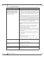
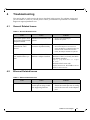
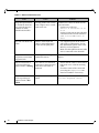
General Related Issues. . . . . . . . . . . . . . . . . . . . . . . . . . . . . . . . . . . . . . . . . . . . .
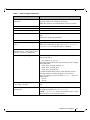
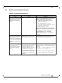
Ethernet Related Issues . . . . . . . . . . . . . . . . . . . . . . . . . . . . . . . . . . . . . . . . . . . .
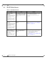
Performance Related Issues . . . . . . . . . . . . . . . . . . . . . . . . . . . . . . . . . . . . . . . . .
SR-IOV Related Issues . . . . . . . . . . . . . . . . . . . . . . . . . . . . . . . . . . . . . . . . . . . .
69
69
71
72
Mellanox Technologies
5
Rev 3.1-1.0.4
List of Tables
Table 1:
Table 2:
Table 3:
Table 4:
Table 5:
Table 6:
Table 7:
Table 8:
Table 9:
Table 10:
Table 11:
6
Document Revision History . . . . . . . . . . . . . . . . . . . . . . . . . . . . . . . . . . . . . . . . . . . . . . . . 7
Abbreviations and Acronyms . . . . . . . . . . . . . . . . . . . . . . . . . . . . . . . . . . . . . . . . . . . . . . 11
Glossary . . . . . . . . . . . . . . . . . . . . . . . . . . . . . . . . . . . . . . . . . . . . . . . . . . . . . . . . . . . . . . . 12
Reference Documents . . . . . . . . . . . . . . . . . . . . . . . . . . . . . . . . . . . . . . . . . . . . . . . . . . . . 12
MLNX_EN Software Components . . . . . . . . . . . . . . . . . . . . . . . . . . . . . . . . . . . . . . . . . . 14
Flow Specific Parameters . . . . . . . . . . . . . . . . . . . . . . . . . . . . . . . . . . . . . . . . . . . . . . . . . 36
ethtool Supported Options . . . . . . . . . . . . . . . . . . . . . . . . . . . . . . . . . . . . . . . . . . . . . . . . . 55
General Related Issues. . . . . . . . . . . . . . . . . . . . . . . . . . . . . . . . . . . . . . . . . . . . . . . . . . . . 69
Ethernet Related Issues . . . . . . . . . . . . . . . . . . . . . . . . . . . . . . . . . . . . . . . . . . . . . . . . . . . 69
Performance Related Issues. . . . . . . . . . . . . . . . . . . . . . . . . . . . . . . . . . . . . . . . . . . . . . . . 71
SR-IOV Related Issues . . . . . . . . . . . . . . . . . . . . . . . . . . . . . . . . . . . . . . . . . . . . . . . . . . . 72
Mellanox Technologies
Rev 3.1-1.0.4
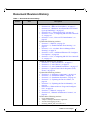
Document Revision History
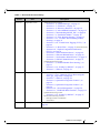
Table 1 - Document Revision History
Release
Date
Description
3.1-1.0.4
October 08, 2015
• Added the following new sections:
• Section 3.14, “Wake-on-LAN (WoL)”, on page 67
• Section 3.15, “Hardware Accelerated 802.1ad VLAN
(Q-in-Q Tunneling)”, on page 67
• Section 3.10.2, “ConnectX-4 ECN”, on page 63
• Section 3.4.1.2.2, “Configuring SR-IOV for ConnectX4”, on page 43
• Section 3.4.1.2.3, “Note on VFs Initialization”, on
page 45
• Updated the following sections:
• Section 3.7, “Ethtool”, on page 54
• Section 3.3.1, “Enable/Disable Flow Steering”, on
page 33
• Section 3.3.2.1, “A0 Static Device Managed Flow
Steering”, on page 35
• Section 3.4.1.6.2, “Additional Ethernet VF Configuration Options”, on page 49
• Section 3.4.1.2.2, “Configuring SR-IOV for ConnectX4”, on page 43
3.0-1.0.1
June 21, 2015
• Added the following new sections:
• Section 1.1.5, “mlx4 VPI Driver”, on page 15
• Section 1.1.6, “mlx5 Driver”, on page 15
• Section 1.2.2, “mlx5 Module Parameters”, on page 17
• Section 3.6, “Ignore Frame Check Sequence (FCS)
Errors”, on page 54
• Updated the following sections:
• Section 1.1.2, “Software Components”, on page 14
• Section 2.3.1, “Installation Modes”, on page 18
• Section 2.3.2, “Installation Procedure”, on page 19
• Section 2.7.1, “Updating the Device Online”, on
page 20
• Section 2.7.2, “Updating the Device Manually”, on
page 20
• Section 2.8, “Ethernet Driver Usage and Configuration”, on page 21
• Section 3.7, “Ethtool”, on page 54
• Section 3.12, “Ethernet Performance Counters”, on
page 64
• Removed the following sections:
•
•
•
•
Power Management
Adaptive Interrupt Moderation Algorithm
Virtual Guest Tagging (VGT+)
Installing MLNX_EN on XenServer6.1
Mellanox Technologies
7
Rev 3.1-1.0.4
Table 1 - Document Revision History
Release
2.4-1.0.0.1
Date
January 26, 2015
Description
• Added the following new sections:
• Section 2.8.2, “Updating the Device Online”, on
page 21
• Section 3.4.1.7.1, “FDB Status Reporting”, on page 49
• Section 3.13, “Adaptive Interrupt Moderation Algorithm”, on page 63
• Section 3.13, “RSS Support for IP Fragments”, on
page 67
• Updated Table 7, “ethtool Supported Options,” on page 55
•
•
Updated “ethtool -K eth<x> [options]” flag options
Added the following new flags: “ethtool -s eth<x>
speed <SPEED> autoneg off” and “ethtool -s
eth<x>
advertise <N> autoneg on”
• Updated “port_type_array” parameter description in
Section 3.4.1.2, “Setting Up SR-IOV”, on page 37
• Updated the following sections:
• Section 3.8, “Checksum Offload”, on page 58
• Section 3.4.2, “VXLAN Hardware Stateless Offloads”,
on page 52
• Section 3.4.2.2, “Enabling VXLAN Hardware Stateless
Offloads”, on page 52
• Section 4.3, “Performance Related Issues”, on page 71
2.3-2.0.1
November 27, 2014
•
Added Section
on page 54
8
Mellanox Technologies
3.5.1.5, “Extended Error Handling (EEH)”,
Rev 3.1-1.0.4
Table 1 - Document Revision History
Release
2.3-1.0.0
Date
September, 2014
Description
•
Added the following sections:
•
•
•
•
•
•
•
•
•
•
•
•
•
•
•
•
Updated the following section:
•
•
•
2.2-1.0.1
May 2014
•
•
•
•
•
2.1-1.0.0
January 2014
Section 3.3.1, “Enable/Disable Flow Steering”, on
page 33
Section 3.4.1.2, “Setting Up SR-IOV”, on page 37
Section 3.7, “Ethtool”, on page 54
Added the following sections:
•
•
Section 1.1.1, “Tarball Package”, on page 13
Section 1.1.3, “Firmware”, on page 14
Section 1.1.4, “Directory Structure”, on page 14
Section 1.2.1, “mlx4 Module Parameters”, on page 15
Section 2.2, “Downloading MLNX_EN”, on page 18
Section 2.3.1, “Installation Modes”, on page 18
Section 3.3.2, “Flow Steering Support”, on page 35
Section 3.3.2.1, “A0 Static Device Managed Flow
Steering”, on page 35
Section 3.4.1.8, “Virtual Guest Tagging (VGT+)”, on
page 46
Section 3.5.1, “Reset Flow”, on page 53 and its subsections
Section 3.10, “Explicit Congestion Notification
(ECN)”, on page 62
Section 4.1, “General Related Issues”, on page 69
Section 4.2, “Ethernet Related Issues”, on page 69
Section 4.3, “Performance Related Issues”, on page 71
Section 4.4, “SR-IOV Related Issues”, on page 72
Section 3.4.1.6.3, “Mapping VFs to Ports using the
mlnx_get_vfs.pl Tool”, on page 49
Section 3.7, “Ethtool”, on page 54
Section 3.9, “Quantized Congestion Control”, on
page 59
Section 3.9, “Quantized Congestion Control”, on
page 59
Section 3.10, “Power Management”, on page 58
Section 3.11, “XOR RSS Hash Function”, on page 64
•
•
Updated the following section:
• Section 3.4.1.2, “Setting Up
Removed the following sections:
• Burning Firmware with SR-IOV
• Performance
SR-IOV”, on page 37
Added Section 3.12, “Ethernet Performance Counters”, on
page 64
Mellanox Technologies
9
Rev 3.1-1.0.4
Table 1 - Document Revision History
Release
2.0-3.0.0
Date
October 2013
Description
•
Added the following sections:
Section 3.4.1, “Single Root IO Virtualization (SRIOV)”, on page 37
• Section 3.3, “Flow Steering”, on page 33
• Section 3.2, “Time-Stamping Service”, on page 30
•
10
Mellanox Technologies
Rev 3.1-1.0.4
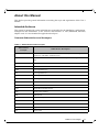
About this Manual
This Preface provides general information concerning the scope and organization of this User’s
Manual.
Intended Audience
This manual is intended for system administrators responsible for the installation, configuration,
management and maintenance of the software and hardware of VPI (InfiniBand, Ethernet)
adapter cards. It is also intended for application developers.
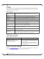
Common Abbreviations and Acronyms
Table 2 - Abbreviations and Acronyms
Abbreviation /
Acronym
Whole Word / Description
B
(Capital) ‘B’ is used to indicate size in bytes or multiples of bytes (e.g., 1KB =
1024 bytes, and 1MB = 1048576 bytes)
b
(Small) ‘b’ is used to indicate size in bits or multiples of bits (e.g., 1Kb = 1024
bits)
FW
Firmware
HW
Hardware
LSB
Least significant byte
lsb
Least significant bit
MSB
Most significant byte
msb
Most significant bit
NIC
Network Interface Card
SW
Software
VPI
Virtual Protocol Interconnect
PFC
Priority Flow Control
PR
Path Record
RDS
Reliable Datagram Sockets
SL
Service Level
QoS
Quality of Service
ULP
Upper Level Protocol
VL
Virtual Lane
Mellanox Technologies
11
Rev 3.1-1.0.4
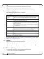
Glossary
The following is a list of concepts and terms related to InfiniBand in general and to Subnet Managers in particular. It is included here for ease of reference, but the main reference remains the
InfiniBand Architecture Specification.
Table 3 - Glossary
Channel Adapter (CA),
Host Channel Adapter
(HCA)
An IB device that terminates an IB link and executes transport functions. This
may be an HCA (Host CA) or a TCA (Target CA).
HCA Card
A network adapter card based on an InfiniBand channel adapter device.
IB Devices
Integrated circuit implementing InfiniBand compliant communication.
In-Band
A term assigned to administration activities traversing the IB connectivity only.
Local Port
The IB port of the HCA through which IBDIAG tools connect to the IB fabric.
Master Subnet Manager
The Subnet Manager that is authoritative, that has the reference configuration
information for the subnet. See Subnet Manager.
Multicast Forwarding
Tables
A table that exists in every switch providing the list of ports to forward received
multicast packet. The table is organized by MLID.
Network Interface Card
(NIC)
A network adapter card that plugs into the PCI Express slot and provides one or
more ports to an Ethernet network.
Unicast Linear Forwarding Tables (LFT)
A table that exists in every switch providing the port through which packets
should be sent to each LID.
Virtual Protocol Interconnet (VPI)
A Mellanox Technologies technology that allows Mellanox channel adapter
devices (ConnectX®) to simultaneously connect to an InfiniBand subnet and a
10GigE subnet (each subnet connects to one of the adpater ports)
Related Documentation
Table 4 - Reference Documents
Document Name
IEEE Std 802.3ae™-2002
(Amendment to IEEE Std 802.3-2002)
Document # PDF: SS94996
Description
Part 3: Carrier Sense Multiple Access with Collision
Detection (CSMA/CD) Access Method and Physical
Layer Specifications
Amendment: Media Access Control (MAC) Parameters, Physical Layers, and Management Parameters
for 10 Gb/s Operation
Support and Updates Webpage
Please visit http://www.mellanox.com > Products > Software > Ethernet Drivers > Linux Drivers
for downloads, FAQ, troubleshooting, future updates to this manual, etc.
12
Mellanox Technologies
Rev 3.1-1.0.4
1
Overview
This document provides information on the MLNX_EN Linux driver and instructions for installing the driver on Mellanox ConnectX adapter cards supporting:
•
ConnectX®-4:
• Ethernet: 10GigE, 25GigE, 40GigE, 50GigE and 100GigE
•
ConnectX®-4 Lx:
• Ethernet: 10GigE, 25GigE, 40GigE, and 100GigE
•
ConnectX®-3/ConnectX®-3 Pro:
• Ethernet: 10GigE, 40GigE and 56GigE1
•
PCI Express 2.0: 2.5 or 5.0 GT/s
•
PCI Express 3.0: 8 GT/s
The MLNX_EN driver release exposes the following capabilities:
•
Single/Dual port
•
Up to 16 Rx queues per port
•
16 Tx queues per port
•
Rx steering mode: Receive Core Affinity (RCA)
•
MSI-X or INTx
•
Adaptive interrupt moderation
•
HW Tx/Rx checksum calculation
•
Large Send Offload (i.e., TCP Segmentation Offload)
•
Large Receive Offload
•
Multi-core NAPI support
•
VLAN Tx/Rx acceleration (HW VLAN stripping/insertion)
•
Ethtool support
•
Net device statistics
•
SR-IOV support
•
Flow steering
•
Ethernet Time Stamping
1.1
MLNX_EN Package Contents
1.1.1
Tarball Package
MLNX_EN for Linux is provided as a tarball that includes source code and firmware. The tarball
contains an installation script (called install.sh) that performs the necessary steps to accomplish
the following:
•
Discover the currently installed kernel
1. 56 GbE is a Mellanox propriety link speed and can be achieved while connecting a Mellanox adapter cards to Mellanox SX10XX switch series
or connecting a Mellanox adapter card to another Mellanox adapter card.
Mellanox Technologies
13
Rev 3.1-1.0.4
1.1.2
Overview
•
Uninstall any previously installed MLNX_OFED/MLNX_EN packages
•
Install the MLNX_EN binary (if they are available for the current kernel)
•
Identify the currently installed HCAs and perform the required firmware updates
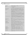
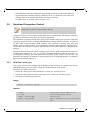
Software Components
MLNX_EN contains the following software components:
Table 5 - MLNX_EN Software Components
Components
Description
mlx5 driver
mlx5 is the low level driver implementation for the ConnectX®-4 adapters
designed by Mellanox Technologies. ConnectX®-4 operates as a VPI adapter.
mlx5_core
Acts as a library of common functions (e.g. initializing the device after reset)
required by the ConnectX®-4 adapter cards.
mlx4 driver
mlx4 is the low level driver implementation for the ConnectX adapters designed
by Mellanox Technologies. The ConnectX can operate as an InfiniBand adapter
and as an Ethernet NIC.
To accommodate the two flavors, the driver is split into modules: mlx4_core, mlx4_en, and mlx4_ib.
Note: mlx4_ib is not part of this package.
mlx4_core
Handles low-level functions like device initialization and firmware commands
processing. Also controls resource allocation so that the InfiniBand, Ethernet and
FC functions can share a device without interfering with each other.
mlx4_en
Handles Ethernet specific functions and plugs into the netdev mid-layer.
mstflint
An application to burn a firmware binary image.
Software modules
Source code for all software modules (for use under conditions mentioned in the
modules' LICENSE files)
Documentation
Release Notes, User Manual
For further information, please refer to Section 1.1.5, “mlx4 VPI Driver”, on page 15 and
Section 1.1.6, “mlx5 Driver”, on page 15.
1.1.3
Firmware
The tarball image includes the following firmware items:
1.1.4
•
Firmware images (.bin format) for ConnectX®-2/ConnectX®-3/ConnectX®-3 Pro/
ConnectX®-4 and ConnectX®-4 Lx network adapters
•
Firmware configuration (.INI) files for Mellanox standard network adapter cards and
custom cards
Directory Structure
The tarball image of MLNX_EN contains the following files and directories:
•
14
install.sh - This is the MLNX_EN installation script.
Mellanox Technologies
Rev 3.1-1.0.4
1.1.5
•
mlnx_en_uninstall.sh - This is the MLNX_EN un-installation script.
•
firmware/ - Directory of the Mellanox HCA firmware images
•
SOURCES/ - Directory of the MLNX_EN source tarball
•
SRPM based - A script required to rebuild MLNX_EN for customized kernel version on
supported RPM based Linux Distribution
mlx4 VPI Driver
mlx4 is the low level driver implementation for the ConnectX® family adapters designed by
Mellanox Technologies. The MLNX_EN driver supports Ethernet NIC configurations. To
accommodate the supported configurations, the driver is split into the following modules:
mlx4_core
Handles low-level functions like device initialization and firmware commands processing. Also
controls resource allocation so that the Ethernet functions can share the device without interfering with each other.
mlx4_en
A 10/40GigE driver under drivers/net/ethernet/mellanox/mlx4 that handles Ethernet specific
functions and plugs into the netdev mid-layer
1.1.6
mlx5 Driver
mlx5 is the low level driver implementation for the ConnectX®-4 adapters designed by Mellanox Technologies. ConnectX®-4 operates as a VPI adapter. The mlx5 driver is comprised of the
following kernel modules:
mlx5_core
Acts as a library of common functions (e.g. initializing the device after reset) required by the
ConnectX®-4 adapter cards. mlx5_core driver also implements the Ethernet interfaces for ConnectX®-4. Unlike mlx4_en/core, mlx5 drivers does not require the mlx5_en module as the Ethernet functionalities are built-in, in the mlx5_core module.
1.2
Module Parameters
1.2.1
mlx4 Module Parameters
In order to set mlx4 parameters, add the following line(s) to /etc/modprobe.conf:
options mlx4_core parameter=<value>
and/or
options mlx4_en
parameter=<value>
The following sections list the available mlx4 parameters.
Mellanox Technologies
15
Rev 3.1-1.0.4
Overview
1.2.1.1 mlx4_core Parameters
set_4k_mtu:
debug_level:
msi_x:
enable_sys_tune:
block_loopback:
num_vfs:
probe_vf:
log_num_mgm_entry_size:
high_rate_steer:
fast_drop:
enable_64b_cqe_eqe:
log_num_mac:
log_num_vlan:
log_mtts_per_seg:
port_type_array:
log_num_qp:
log_num_srq:
log_rdmarc_per_qp:
log_num_cq:
log_num_mcg:
log_num_mpt:
16
Mellanox Technologies
(Obsolete) attempt to set 4K MTU to all ConnectX ports (int)
Enable debug tracing if > 0 (int)
0 - don't use MSI-X,
1 - use MSI-X,
>1 - limit number of MSI-X irqs to msi_x (non-SRIOV only) (int)
Tune the cpu's for better performance (default 0) (int)
Block multicast loopback packets if > 0 (default: 1) (int)
Either a single value (e.g. '5') to define uniform num_vfs
value for all devices functions or a string to map device function numbers to their num_vfs values (e.g. '0000:04:00.05,002b:1c:0b.a-15').
Hexadecimal digits for the device function (e.g. 002b:1c:0b.a)
and decimal for num_vfs value (e.g. 15). (string)
Either a single value (e.g. '3') to indicate that the Hypervisor driver itself should activate this number of VFs for each
HCA on the host, or a string to map device function numbers to
their probe_vf values (e.g. '0000:04:00.0-3,002b:1c:0b.a-13').
Hexadecimal digits for the device function (e.g. 002b:1c:0b.a)
and decimal for probe_vf value (e.g. 13). (string)
log mgm size, that defines the num of qp per mcg, for example:
10 gives 248.range: 7 <= log_num_mgm_entry_size <= 12. To
activate device managed flow steering when available, set to 1 (int)
Enable steering mode for higher packet rate (default off)
(int)
Enable fast packet drop when no recieve WQEs are posted (int)
Enable 64 byte CQEs/EQEs when the FW supports this if non-zero
(default: 1) (int)
Log2 max number of MACs per ETH port (1-7) (int)
(Obsolete) Log2 max number of VLANs per ETH port (0-7) (int)
Log2 number of MTT entries per segment (0-7) (default: 0) (int)
Either pair of values (e.g. '1,2') to define uniform port1/
port2 types configuration for all devices functions or a
string to map device function numbers to their pair of port
types values (e.g. '0000:04:00.0-1;2,002b:1c:0b.a-1;1').
Valid port types: 1-ib, 2-eth, 3-auto, 4-N/A
If only a single port is available, use the N/A port type for
port2 (e.g '1,4').
log maximum number of QPs per HCA (default: 19) (int)
log maximum number of SRQs per HCA (default: 16) (int)
log number of RDMARC buffers per QP (default: 4) (int)
log maximum number of CQs per HCA (default: 16) (int)
log maximum number of multicast groups per HCA (default: 13)
(int)
log maximum number of memory protection table entries per HCA
(default: 19) (int)
Rev 3.1-1.0.4
log_num_mtt:
enable_qos:
internal_err_reset:
log maximum number of memory translation table segments per
HCA (default: max(20, 2*MTTs for register all of the host memory limited to 30)) (int)
Enable Quality of Service support in the HCA (default: off)
(bool)
Reset device on internal errors if non-zero (default is 1)
(int)
1.2.1.2 mlx4_en Parameters
inline_thold:
udp_rss:
pfctx:
pfcrx:
1.2.2
Threshold for using inline data (int)
Default and max value is 104 bytes. Saves PCI read operation
transaction, packet less then threshold size will be copied to
hw buffer directly.
Enable RSS for incoming UDP traffic (uint)
On by default. Once disabled no RSS for incoming UDP traffic
will be done.
Priority based Flow Control policy on TX[7:0]. Per priority
bit mask (uint)
Priority based Flow Control policy on RX[7:0]. Per priority
bit mask (uint)
mlx5 Module Parameters
The mlx5_core module supports a single parameter used to select the profile which defines the
number of resources supported. The parameter name for selecting the profile is prof_sel.
The supported values for profiles are:
•
0 - for medium resources, medium performance
•
1 - for low resources
•
2 - for high performance (int) (default)
Mellanox Technologies
17
Rev 3.1-1.0.4
2
Installation
Installation
This chapter describes how to install and test the MLNX_EN for Linux package on a single host
machine with Mellanox InfiniBand and/or Ethernet adapter hardware installed.
2.1
2.2
Software Dependencies
•
To install the driver software, kernel sources must be installed on the machine.
•
MLNX_EN driver cannot coexist with OFED software on the same machine. Hence
when installing MLNX_EN all OFED packages should be removed (run the
install.sh script).
Downloading MLNX_EN
Step 1.
Verify that the system has a Mellanox network adapter (HCA/NIC) installed.
The following example shows a system with an installed Mellanox HCA:
# lspci -v | grep Mellanox
06:00.0 Network controller: Mellanox Technologies MT27500 Family [ConnectX-3]
Subsystem: Mellanox Technologies Device 0024
Step 2.
Download the tarball image to your host.
The image’s name has the format MLNX_EN-<ver>.tgz. You can download it from
http://www.mellanox.com > Products > Software> Ethernet Drivers.
Step 3.
2.3
Use the md5sum utility to confirm the file integrity of your tarball image.
Installing MLNX_EN
The installation script, install.sh, performs the following:
2.3.1
•
Discovers the currently installed kernel
•
Uninstalls any previously installed MLNX_OFED/MLNX_EN packages
•
Installs the MLNX_EN binary (if they are available for the current kernel)
•
Identifies the currently installed Ethernet network adapters and automatically upgrades
the firmware
Installation Modes
mlnx_en installer supports 2 modes of installation. The install scripts selects the mode of driver
installation depending of the running OS/kernel version.
•
Kernel Module Packaging (KMP) mode, where the source rpm is rebuilt for each
installed flavor of the kernel. This mode is used for RedHat and SUSE distributions.
•
Non KMP installation mode, where the sources are rebuilt with the running kernel. This
mode is used for vanilla kernels.
If the Vanilla kernel is installed as rpm, please use the "--disable-kmp" flag when
installing the driver.
18
Mellanox Technologies
Rev 3.1-1.0.4
The package consists of several source RPMs. The install script rebuilds the source RPMs and
then installs the created binary RPMs. The created kernel module binaries are located at:
•
For KMP RPMs installation:
• On SLES (mellanox-mlnx-en-kmp RPM):
/lib/modules/<kernel-ver>/updates/mlnx-en
• On RHEL (kmod-mellanox-mlnx-en RPM):
/lib/modules/<kernel-ver>/extra/mlnx-en
•
For non-KMP RPMs (mlnx_en RPM):
• On SLES:
/lib/modules/<kernel-ver>/updates/mlnx_en
• On RHEL:
/lib/modules/<kernel-ver>/extra/mlnx_en
The kernel module sources are placed under /usr/src/mellanox-mlnx-en-<ver>/.
2.3.2
Installation Procedure
Step 1.
Login to the installation machine as root.
Step 2.
Extract the tarball image on your machine.
#> tar xzvf mlnx_en-3.0-1.0.1.tgz
Step 3.
Change the working directory.
#> cd mlnx_en-3.0-1.0.1
Step 4.
Run the installation script.
#> ./install.sh
Step 5.
Load the driver.
# /etc/init.d/mlnx-en.d restart
Unloading NIC driver:
Loading NIC driver:
[ OK ]
[ OK ]
The "/etc/init.d/mlnx-en.d" service script will load both the mlx4 and/or mlx5 drivers
as set in the "/etc/mlnx-en.conf" configurations file.
The result is a new net-device appearing in the 'ifconfig -a' output.
2.4
Unloading MLNX_EN
To unload the Ethernet driver:
# /etc/init.d/mlnx-en.d stop
Unloading NIC driver:
2.5
[ OK ]
Uninstalling MLNX_EN
Use the script /sbin/mlnx_en_uninstall.sh to uninstall the Mellanox OFED package.
Mellanox Technologies
19
Rev 3.1-1.0.4
2.6
Installation
Recompiling MLNX_EN
To recompile the driver:
Step 1.
Enter the source directory.
cp -a /usr/src/mlnx-en-3.0/ /tmp
cd /tmp/mlnx-en-3.0
Step 2.
Apply kernel backport patch.
#> scripts/mlnx_en_patch.sh
Step 3.
Compile the driver sources.
#> make
Step 4.
Install the driver kernel modules.
#> make install
2.7
Updating Firmware After Installation
The firmware can be updated in one of the following methods.
2.7.1
Updating the Device Online
To update the device online on the machine from Mellanox site, use the following command line:
mlxfwmanager --online -u -d <device>
Example:
mlxfwmanager --online -u -d 0000:09:00.0
Querying Mellanox devices firmware ...
Device #1:
---------Device Type:
Part Number:
Description:
40GigE;
PSID:
PCI Device Name:
Port1 GUID:
Port2 MAC:
Versions:
FW
ConnectX3
MCX354A-FCA_A2-A4
ConnectX-3 VPI adapter card; dual-port QSFP; FDR IB (56Gb/s) and
PCIe3.0 x8 8GT/s; RoHS R6
MT_1020120019
0000:09:00.0
0002c9000100d051
0002c9000002
Current
Available
2.33.5000
2.34.5000
Status:
Update required
--------Found 1 device(s) requiring firmware update. Please use -u flag to perform the update.
2.7.2
Updating the Device Manually
In case you ran the install script with the ‘--without-fw-update’ option or you are using
an OEM card and now you wish to (manually) update firmware on your adapter card(s), you need
to perform the steps below. The following steps are also appropriate in case you wish to burn
20
Mellanox Technologies
Rev 3.1-1.0.4
newer firmware that you have downloaded from Mellanox Technologies’ Web site (http://
www.mellanox.com > Support > Firmware Download).
Step 1.
Get the device’s PSID.
mlxfwmanager_pci | grep PSID
PSID:
MT_1210110019
Step 2.
Download the firmware BIN file from the Mellanox website or the OEM website.
Step 3.
Burn the firmware.
mlxfwmanager_pci -i <fw_file.bin>
Step 4.
2.8
Reboot your machine after the firmware burning is completed.
Ethernet Driver Usage and Configuration
To assign an IP address to the interface:
#> ifconfig eth<xa> <ip>
a. 'x' is the OS assigned interface number
To check driver and device information:
#> ethtool -i eth<x>
Example:
#> ethtool -i eth2
driver: mlx4_en
version: 2.1.8 (Oct 06 2013)
firmware-version: 2.30.3110
bus-info: 0000:1a:00.0
To query stateless offload status:
#> ethtool -k eth<x>
To set stateless offload status:
#> ethtool -K eth<x> [rx on|off] [tx on|off] [sg on|off] [tso on|off] [lro on|off]
To query interrupt coalescing settings:
#> ethtool -c eth<x>
To enable/disable adaptive interrupt moderation:
#>ethtool -C eth<x> adaptive-rx on|off
By default, the driver uses adaptive interrupt moderation for the receive path, which adjusts the moderation time to the traffic pattern.
To set the values for packet rate limits and for moderation time high and low:
#> ethtool -C eth<x> [pkt-rate-low N] [pkt-rate-high N] [rx-usecs-low N] [rx-usecs-high N]
Above an upper limit of packet rate, adaptive moderation will set the moderation time to its highest
value. Below a lower limit of packet rate, the moderation time will be set to its lowest value.
To set interrupt coalescing settings when adaptive moderation is disabled:
#> ethtool -C eth<x> [rx-usecs N] [rx-frames N]
Mellanox Technologies
21
Rev 3.1-1.0.4
Installation
usec settings correspond to the time to wait after the *last* packet is sent/received before
triggering an interrupt.
[ConnectX-3/ConnectX-3 Pro] To query pause frame settings:
#> ethtool -a eth<x>
[ConnectX-3/ConnectX-3 Pro] To set pause frame settings:
#> ethtool -A eth<x> [rx on|off] [tx on|off]
To query ring size values:
#> ethtool -g eth<x>
To modify rings size:
#> ethtool -G eth<x> [rx <N>] [tx <N>]
To obtain additional device statistics:
#> ethtool -S eth<x>
[ConnectX-3/ConnectX-3 Pro] To perform a self diagnostics test:
#> ethtool -t eth<x>
The driver defaults to the following parameters:
•
Both ports are activated (i.e., a net device is created for each port)
•
The number of Rx rings for each port is the nearest power of 2 of number of cpu cores,
limited by 16.
•
LRO is enabled with 32 concurrent sessions per Rx ring
Some of these values can be changed using module parameters, which can be displayed by running:
#> modinfo mlx4_en
To set non-default values to module parameters, add to the /etc/modprobe.conf file:
"options mlx4_en <param_name>=<value> <param_name>=<value> ..."
Values of all parameters can be observed in /sys/module/mlx4_en/parameters/.
2.9
Performance Tunining
For further information on Linux performance, please refer to the Performance Tuning Guide for
Mellanox Network Adapters.
22
Mellanox Technologies
Rev 3.1-1.0.4
3
Feature Overview and Configuration
3.1
Quality of Service
Quality of Service (QoS) is a mechanism of assigning a priority to a network flow (socket,
rdma_cm connection) and manage its guarantees, limitations and its priority over other flows.
This is accomplished by mapping the user's priority to a hardware TC (traffic class) through a 2/
3 stages process. The TC is assigned with the QoS attributes and the different flows behave
accordingly
3.1.1
Mapping Traffic to Traffic Classes
Mapping traffic to TCs consists of several actions which are user controllable, some controlled
by the application itself and others by the system/network administrators.
The following is the general mapping traffic to Traffic Classes flow:
1. The application sets the required Type of Service (ToS).
2. The ToS is translated into a Socket Priority (sk_prio).
3. The sk_prio is mapped to a User Priority (UP) by the system administrator (some applications set sk_prio directly).
4. The UP is mapped to TC by the network/system administrator.
5. TCs hold the actual QoS parameters
QoS can be applied on the following types of traffic. However, the general QoS flow may vary
among them:
3.1.2
•
Plain Ethernet - Applications use regular inet sockets and the traffic passes via the kernel Ethernet driver
•
RoCE - Applications use the RDMA API to transmit using QPs
•
Raw Ethernet QP - Application use VERBs API to transmit using a Raw Ethernet QP
Plain Ethernet Quality of Service Mapping
Applications use regular inet sockets and the traffic passes via the kernel Ethernet driver.
The following is the Plain Ethernet QoS mapping flow:
1. The application sets the ToS of the socket using setsockopt (IP_TOS, value).
2. ToS is translated into the sk_prio using a fixed translation:
TOS
TOS
TOS
TOS
0 <=> sk_prio 0
8 <=> sk_prio 2
24 <=> sk_prio 4
16 <=> sk_prio 6
3. The Socket Priority is mapped to the UP:
• If the underlying device is a VLAN device, egress_map is used controlled by the vconfig
command. This is per VLAN mapping.
• If the underlying device is not a VLAN device, the tc command is used. In this case, even
though tc manual states that the mapping is from the sk_prio to the TC number, the mlx4_en driver interprets this as a sk_prio to UP mapping.
Mellanox Technologies
23
Rev 3.1-1.0.4
Feature Overview and Configuration
Mapping the sk_prio to the UP is done by using tc_wrap.py -i <dev name> -u
0,1,2,3,4,5,6,7
4. The the UP is mapped to the TC as configured by the mlnx_qos tool or by the lldpad daemon
if DCBX is used.
Socket applications can use setsockopt (SK_PRIO, value) to directly set the sk_prio
of the socket. In this case the ToS to sk_prio fixed mapping is not needed. This allows
the application and the administrator to utilize more than the 4 values possible via ToS.
In case of VLAN interface, the UP obtained according to the above mapping is also used
in the VLAN tag of the traffic
3.1.3
Map Priorities with tc_wrap.py/mlnx_qos
Network flow that can be managed by QoS attributes is described by a User Priority (UP). A
user's sk_prio is mapped to UP which in turn is mapped into TC.
•
Indicating the UP
• When the user uses sk_prio, it is mapped into a UP by the ‘tc’ tool. This is done by the
tc_wrap.py tool which gets a list of <= 16 comma separated UP and maps the sk_prio to
the specified UP.
For example, tc_wrap.py -ieth0 -u 1,5 maps sk_prio 0 of eth0 device to UP 1 and
sk_prio 1 to UP 5.
• Setting set_egress_map in VLAN, maps the skb_priority of the VLAN to a vlan_qos.
The vlan_qos is represents a UP for the VLAN device.
• In RoCE, rdma_set_option with RDMA_OPTION_ID_TOS could be used to set the UP
• When creating QPs, the sl field in ibv_modify_qp command represents the UP
•
Indicating the TC
• After mapping the skb_priority to UP, one should map the UP into a TC. This assigns
the user priority to a specific hardware traffic class. In order to do that, mlnx_qos should
be used. mlnx_qos gets a list of a mapping between UPs to TCs. For example, mlnx_qos ieth0 -p 0,0,0,0,1,1,1,1 maps UPs 0-3 to TC0, and Ups 4-7 to TC1.
3.1.4
Quality of Service Properties
The different QoS properties that can be assigned to a TC are:
•
Strict Priority (see “Strict Priority”)
•
Minimal Bandwidth Guarantee (ETS) (see “Minimal Bandwidth Guarantee (ETS)”)
•
Rate Limit (see “Rate Limit”)
3.1.4.1 Strict Priority
When setting a TC's transmission algorithm to be 'strict', then this TC has absolute (strict) priority over other TC strict priorities coming before it (as determined by the TC number: TC 7 is
highest priority, TC 0 is lowest). It also has an absolute priority over non strict TCs (ETS).
24
Mellanox Technologies
Rev 3.1-1.0.4
This property needs to be used with care, as it may easily cause starvation of other TCs.
A higher strict priority TC is always given the first chance to transmit. Only if the highest strict
priority TC has nothing more to transmit, will the next highest TC be considered.
Non strict priority TCs will be considered last to transmit.
This property is extremely useful for low latency low bandwidth traffic. Traffic that needs to get
immediate service when it exists, but is not of high volume to starve other transmitters in the system.
3.1.4.2 Minimal Bandwidth Guarantee (ETS)
After servicing the strict priority TCs, the amount of bandwidth (BW) left on the wire may be
split among other TCs according to a minimal guarantee policy.
If, for instance, TC0 is set to 80% guarantee and TC1 to 20% (the TCs sum must be 100), then
the BW left after servicing all strict priority TCs will be split according to this ratio.
Since this is a minimal guarantee, there is no maximum enforcement. This means, in the same
example, that if TC1 did not use its share of 20%, the reminder will be used by TC0.
ETS is configured using the mlnx_qos tool (“mlnx_qos”) which allows you to:
•
Assign a transmission algorithm to each TC (strict or ETS)
•
Set minimal BW guarantee to ETS TCs
Usage:
mlnx_qos -i [options]
3.1.4.3 Rate Limit
Rate limit defines a maximum bandwidth allowed for a TC. Please note that 10% deviation from
the requested values is considered acceptable.
3.1.5
Quality of Service Tools
3.1.5.1 mlnx_qos
mlnx_qos is a centralized tool used to configure QoS features of the local host. It communicates
directly with the driver thus does not require setting up a DCBX daemon on the system.
The mlnx_qos tool enables the administrator of the system to:
•
Inspect the current QoS mappings and configuration
The tool will also display maps configured by TC and vconfig set_egress_map tools, in order to
give a centralized view of all QoS mappings.
•
Set UP to TC mapping
•
Assign a transmission algorithm to each TC (strict or ETS)
•
Set minimal BW guarantee to ETS TCs
•
Set rate limit to TCs
Mellanox Technologies
25
Rev 3.1-1.0.4
Feature Overview and Configuration
For unlimited ratelimit set the ratelimit to 0.
Usage:
mlnx_qos -i <interface> [options]
Options:
--version
show program's version number and exit
-h, --help
show this help message and exit
-p LIST, --prio_tc=LIST
maps UPs to TCs. LIST is 8 comma seperated TC numbers.
Example: 0,0,0,0,1,1,1,1 maps UPs 0-3 to TC0, and UPs
4-7 to TC1
-s LIST, --tsa=LIST Transmission algorithm for each TC. LIST is comma
seperated algorithm names for each TC. Possible
algorithms: strict, etc. Example: ets,strict,ets sets
TC0,TC2 to ETS and TC1 to strict. The rest are
unchanged.
-t LIST, --tcbw=LIST Set minimal guaranteed %BW for ETS TCs. LIST is comma
seperated percents for each TC. Values set to TCs that
are not configured to ETS algorithm are ignored, but
must be present. Example: if TC0,TC2 are set to ETS,
then 10,0,90 will set TC0 to 10% and TC2 to 90%.
Percents must sum to 100.
-r LIST, --ratelimit=LIST
Rate limit for TCs (in Gbps). LIST is a comma
seperated Gbps limit for each TC. Example: 1,8,8 will
limit TC0 to 1Gbps, and TC1,TC2 to 8 Gbps each.
-i INTF, --interface=INTF
Interface name
-a
Show all interface's TCs
26
Mellanox Technologies
Rev 3.1-1.0.4
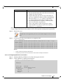
3.1.5.1.1 Get Current Configuration
tc: 0 ratelimit: unlimited, tsa:
up: 0
skprio: 0
skprio: 1
skprio: 2 (tos:
skprio: 3
skprio: 4 (tos:
skprio: 5
skprio: 6 (tos:
skprio: 7
skprio: 8
skprio: 9
skprio: 10
skprio: 11
skprio: 12
skprio: 13
skprio: 14
skprio: 15
up: 1
up: 2
up: 3
up: 4
up: 5
up: 6
up: 7
strict
8)
24)
16)
Mellanox Technologies
27
Rev 3.1-1.0.4
Feature Overview and Configuration
3.1.5.1.2 Set ratelimit. 3Gbps for tc0 4Gbps for tc1 and 2Gbps for tc2
tc: 0 ratelimit: 3 Gbps,
up: 0
skprio:
skprio:
skprio:
skprio:
skprio:
skprio:
skprio:
skprio:
skprio:
skprio:
skprio:
skprio:
skprio:
skprio:
skprio:
skprio:
up: 1
up: 2
up: 3
up: 4
up: 5
up: 6
up: 7
tsa: strict
0
1
2 (tos: 8)
3
4 (tos: 24)
5
6 (tos: 16)
7
8
9
10
11
12
13
14
15
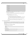
3.1.5.1.3 Configure QoS. map UP 0,7 to tc0, 1,2,3 to tc1 and 4,5,6 to tc 2. set tc0,tc1 as ets and tc2 as
strict. divide ets 30% for tc0 and 70% for tc1:
mlnx_qos -i eth3 -s ets,ets,strict -p 0,1,1,1,2,2,2 -t 30,70
tc: 0 ratelimit: 3 Gbps, tsa: ets, bw: 30%
up: 0
skprio: 0
skprio: 1
skprio: 2 (tos: 8)
skprio: 3
skprio: 4 (tos: 24)
skprio: 5
skprio: 6 (tos: 16)
skprio: 7
skprio: 8
skprio: 9
skprio: 10
skprio: 11
skprio: 12
skprio: 13
skprio: 14
skprio: 15
28
Mellanox Technologies
Rev 3.1-1.0.4
up: 7
tc: 1 ratelimit: 4 Gbps, tsa: ets, bw: 70%
up: 1
up: 2
up: 3
tc: 2 ratelimit: 2 Gbps, tsa: strict
up: 4
up: 5
up: 6
3.1.5.2 tc and tc_wrap.py
The 'tc' tool is used to setup sk_prio to UP mapping, using the mqprio queue discipline.
In kernels that do not support mqprio (such as 2.6.34), an alternate mapping is created in sysfs.
The 'tc_wrap.py' tool will use either the sysfs or the 'tc' tool to configure the sk_prio to UP
mapping.
Usage:
tc_wrap.py -i <interface> [options]
Options:
--version
show program's version number and exit
-h, --help
show this help message and exit
-u SKPRIO_UP, --skprio_up=SKPRIO_UP maps sk_prio to UP. LIST is <=16 comma separated
UP. index of element is sk_prio.
-i INTF, --interface=INTF
Interface name
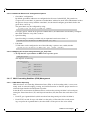
Example: set skprio 0-2 to UP0, and skprio 3-7 to UP1 on eth4
UP 0
skprio:
skprio:
skprio:
skprio:
skprio:
skprio:
skprio:
skprio:
skprio:
skprio:
skprio:
skprio:
0
1
2 (tos: 8)
7
8
9
10
11
12
13
14
15
skprio:
skprio:
skprio:
skprio:
3
4 (tos: 24)
5
6 (tos: 16)
UP 1
UP
UP
UP
UP
UP
UP
2
3
4
5
6
7
Mellanox Technologies
29
Rev 3.1-1.0.4
Feature Overview and Configuration
3.1.5.3 Additional Tools
tc tool compiled with the sch_mqprio module is required to support kernel v2.6.32 or higher.
This is a part of iproute2 package v2.6.32-19 or higher. Otherwise, an alternative custom sysfs
interface is available.
3.2
•
mlnx_qos tool
•
tc_wrap.py
(package: ofed-scripts) requires python >= 2.5
(package: ofed-scripts) requires python >= 2.5
Time-Stamping Service
Time Stamping is currently supported in ConnectX®-3/ConnectX®-3 Pro adapter
cards only.
Time stamping is the process of keeping track of the creation of a packet/ A time-stamping service supports assertions of proof that a datum existed before a particular time. Incoming packets
are time-stamped before they are distributed on the PCI depending on the congestion in the PCI
buffers. Outgoing packets are time-stamped very close to placing them on the wire.
3.2.1
Enabling Time Stamping
Time-stamping is off by default and should be enabled before use.
To enable time stamping for a socket:
•
Call setsockopt() with SO_TIMESTAMPING and with the following flags:
SOF_TIMESTAMPING_TX_HARDWARE: try to obtain send time stamp in hardware
SOF_TIMESTAMPING_TX_SOFTWARE: if SOF_TIMESTAMPING_TX_HARDWARE is off or
fails, then do it in software
SOF_TIMESTAMPING_RX_HARDWARE: return the original, unmodified time stamp
as generated by the hardware
SOF_TIMESTAMPING_RX_SOFTWARE: if SOF_TIMESTAMPING_RX_HARDWARE is off or
fails, then do it in software
SOF_TIMESTAMPING_RAW_HARDWARE: return original raw hardware time stamp
SOF_TIMESTAMPING_SYS_HARDWARE: return hardware time stamp transformed to
the system time base
SOF_TIMESTAMPING_SOFTWARE:
return system time stamp generated in
software
SOF_TIMESTAMPING_TX/RX determine how time stamps are generated.
SOF_TIMESTAMPING_RAW/SYS determine how they are reported
To enable time stamping for a net device:
Admin privileged user can enable/disable time stamping through calling ioctl(sock, SIOCSHWTSTAMP, &ifreq) with following values:
Send side time sampling:
30
Mellanox Technologies
Rev 3.1-1.0.4
• Enabled by ifreq.hwtstamp_config.tx_type when
/* possible values for hwtstamp_config->tx_type */
enum hwtstamp_tx_types {
/*
* No outgoing packet will need hardware time stamping;
* should a packet arrive which asks for it, no hardware
* time stamping will be done.
*/
HWTSTAMP_TX_OFF,
/*
* Enables hardware time stamping for outgoing packets;
* the sender of the packet decides which are to be
* time stamped by setting %SOF_TIMESTAMPING_TX_SOFTWARE
* before sending the packet.
*/
HWTSTAMP_TX_ON,
/*
* Enables time stamping for outgoing packets just as
* HWTSTAMP_TX_ON does, but also enables time stamp insertion
* directly into Sync packets. In this case, transmitted Sync
* packets will not received a time stamp via the socket error
* queue.
*/
HWTSTAMP_TX_ONESTEP_SYNC,
};
Note: for send side time stamping currently only HWTSTAMP_TX_OFF and
HWTSTAMP_TX_ON are supported.
Mellanox Technologies
31
Rev 3.1-1.0.4
Feature Overview and Configuration
Receive side time sampling:
• Enabled by ifreq.hwtstamp_config.rx_filter when
/* possible values for hwtstamp_config->rx_filter */
enum hwtstamp_rx_filters {
/* time stamp no incoming packet at all */
HWTSTAMP_FILTER_NONE,
/* time stamp any incoming packet */
HWTSTAMP_FILTER_ALL,
/* return value: time stamp all packets requested plus some others */
HWTSTAMP_FILTER_SOME,
/* PTP v1, UDP, any kind of event packet */
HWTSTAMP_FILTER_PTP_V1_L4_EVENT,
/* PTP v1, UDP, Sync packet */
HWTSTAMP_FILTER_PTP_V1_L4_SYNC,
/* PTP v1, UDP, Delay_req packet */
HWTSTAMP_FILTER_PTP_V1_L4_DELAY_REQ,
/* PTP v2, UDP, any kind of event packet */
HWTSTAMP_FILTER_PTP_V2_L4_EVENT,
/* PTP v2, UDP, Sync packet */
HWTSTAMP_FILTER_PTP_V2_L4_SYNC,
/* PTP v2, UDP, Delay_req packet */
HWTSTAMP_FILTER_PTP_V2_L4_DELAY_REQ,
/* 802.AS1, Ethernet, any kind of event packet */
HWTSTAMP_FILTER_PTP_V2_L2_EVENT,
/* 802.AS1, Ethernet, Sync packet */
HWTSTAMP_FILTER_PTP_V2_L2_SYNC,
/* 802.AS1, Ethernet, Delay_req packet */
HWTSTAMP_FILTER_PTP_V2_L2_DELAY_REQ,
/* PTP v2/802.AS1, any layer, any kind of event packet */
HWTSTAMP_FILTER_PTP_V2_EVENT,
/* PTP v2/802.AS1, any layer, Sync packet */
HWTSTAMP_FILTER_PTP_V2_SYNC,
/* PTP v2/802.AS1, any layer, Delay_req packet */
HWTSTAMP_FILTER_PTP_V2_DELAY_REQ,
};
Note: for receive side time stamping currently only HWTSTAMP_FILTER_NONE and
HWTSTAMP_FILTER_ALL are supported.
3.2.2
Getting Time Stamping
Once time stamping is enabled time stamp is placed in the socket Ancillary data. recvmsg() can
be used to get this control message for regular incoming packets. For send time stamps the outgoing packet is looped back to the socket's error queue with the send time stamp(s) attached. It can
be received with recvmsg(flags=MSG_ERRQUEUE). The call returns the original outgoing
packet data including all headers preprended down to and including the link layer, the scm_timestamping control message and a sock_extended_err control message with ee_errno==ENOMSG
and ee_origin==SO_EE_ORIGIN_TIMESTAMPING. A socket with such a pending bounced
32
Mellanox Technologies
Rev 3.1-1.0.4
packet is ready for reading as far as select() is concerned. If the outgoing packet has to be fragmented, then only the first fragment is time stamped and returned to the sending socket.
When time-stamping is enabled, VLAN stripping is disabled.
For more info please refer to Documentation/networking/timestamping.txt in kernel.org
3.3
Flow Steering
Flow Steering is applicable to the mlx4 driver only.
Flow steering is a new model which steers network flows based on flow specifications to specific
QPs. Those flows can be either unicast or multicast network flows. In order to maintain flexibility, domains and priorities are used. Flow steering uses a methodology of flow attribute, which is
a combination of L2-L4 flow specifications, a destination QP and a priority. Flow steering rules
could be inserted either by using ethtool or by using InfiniBand verbs. The verbs abstraction uses
an opposed terminology of a flow attribute (ibv_flow_attr), defined by a combination of specifications (struct ibv_flow_spec_*).
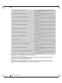
3.3.1
Enable/Disable Flow Steering
Only applicable to the mlx4 driver. Flow Steering is automatically enabled in the mlx5
driver as of MLNX_EN v3.1-1.0.4 and above.
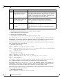
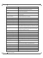
Flow steering is generally enabled when the log_num_mgm_entry_size module parameter is non
positive (e.g., -log_num_mgm_entry_size), meaning the absolute value of the parameter, is a bit
field. Every bit indicates a condition or an option regarding the flow steering mechanism:
reserved
bit
Operation
b5
b4
b3
b2
b1
b0
Description
b0
Force device managed Flow
Steering
When set to 1, it forces HCA to be enabled regardless of
whether NC-SI Flow Steering is supported or not.
b1
Disable IPoIB Flow Steering
When set to 1, it disables the support of IPoIB Flow Steering.
This bit should be set to 1 when "b2- Enable A0 static
DMFS steering" is used (see Section 3.3.2.1, “A0 Static
Device Managed Flow Steering”, on page 35).
b2
Enable A0 static DMFS
steering (see Section 3.3.2.1,
“A0 Static Device Managed
Flow Steering”, on page 35)
When set to 1, A0 static DMFS steering is enabled. This
bit should be set to 0 when "b1- Disable IPoIB Flow Steering" is 0.
Mellanox Technologies
33
Rev 3.1-1.0.4
Feature Overview and Configuration
bit
Operation
Description
b3
Enable DMFS only if the
HCA supports more than
64QPs per MCG entry
When set to 1, DMFS is enabled only if the HCA supports
more than 64 QPs attached to the same rule. For example,
attaching 64VFs to the same multicast address causes
64QPs to be attached to the same MCG. If the HCA supports less than 64 QPs per MCG, B0 is used.
b4
Optimize IPoIB/EoIB steering table for non source IP
rules when possible
When set to 1, IPoIB/EoIB steering table will be optimized to support rules ignoring source IP check.
This optimization is available only when IPoIB Flow
Steering is set.
b5
Optimize steering table for
non source IP rules when
possible
When set to 1, steering table will be optimized to support
rules ignoring source IP check.
This optimization is possible only when DMFS mode is
set.
For example, a value of (-7) means:
•
forcing Flow Steering regardless of NC-SI Flow Steering support
•
disabling IPoIB Flow Steering support
•
enabling A0 static DMFS steering
•
steering table is not optimized for rules ignoring source IP check
The default value of log_num_mgm_entry_size is -10. Meaning Ethernet Flow Steering (i.e
IPoIB DMFS is disabled by default) is enabled by default if NC-SI DMFS is supported and the
HCA supports at least 64 QPs per MCG entry. Otherwise, L2 steering (B0) is used.
When using SR-IOV, flow steering is enabled if there is an adequate amount of space to store the
flow steering table for the guest/master.
To enable Flow Steering:
Step 1.
Open the /etc/modprobe.d/mlnx.conf file.
Step 2.
Set the parameter log_num_mgm_entry_size to a non positive value by writing the option
mlx4_core log_num_mgm_entry_size=<value>.
Step 3.
Restart the driver
To disable Flow Steering:
Step 1.
Open the /etc/modprobe.d/mlnx.conf file.
Step 2.
Remove the options mlx4_core log_num_mgm_entry_size= <value>.
Step 3.
Restart the driver
For example, a value of (-7) means forcing flow steering regardless of NC-SI flow steering support, disabling IPoIB flow steering support and enabling A0 static DMFS steering.
The default value of log_num_mgm_entry_size is -10. Meaning Ethernet Flow Steering (i.e
IPoIB DMFS is disabled by default) is enabled by default if NC-SI DMFS is supported and the
HCA supports at least 64 QPs per MCG entry. Otherwise, L2 steering (B0) is used.
When using SR-IOV, flow steering is enabled if there is an adequate amount of space to store the
flow steering table for the guest/master.
To enable Flow Steering:
Step 1.
34
Open the /etc/modprobe.d/mlnx.conf file.
Mellanox Technologies
Rev 3.1-1.0.4
Step 2.
Set the parameter log_num_mgm_entry_size to a non positive value by writing the option
mlx4_core log_num_mgm_entry_size=<value>.
Step 3.
Restart the driver
To disable Flow Steering:
3.3.2
Step 1.
Open the /etc/modprobe.d/mlnx.conf file.
Step 2.
Remove the options mlx4_core log_num_mgm_entry_size= <value>.
Step 3.
Restart the driver
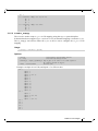
Flow Steering Support
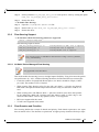
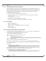
To determine which Flow Steering features are supported:
ethtool --show-priv-flags eth4
The following output is shown:
mlx4_flow_steering_ethernet_l2: on
mlx4_flow_steering_ipv4: on
mlx4_flow_steering_tcp: on
Creating Ethernet L2 (MAC) rules is supported
Creating IPv4 rules is supported
Creating TCP/UDP rules is supported
Flow Steering support in InfiniBand is determined according to the EXP_MANAGED_FLOW_STEERING flag.
3.3.2.1 A0 Static Device Managed Flow Steering
Only applicable to the mlx4 driver.
This mode enables fast steering, however it might impact flexibility. Using it increases the packet
rate performance by ~30%, with the following limitations for Ethernet link-layer unicast QPs:
3.3.3
•
Limits the number of opened RSS Kernel QPs to 96. MACs should be unique (1 MAC
per 1 QP). The number of VFs is limited.
•
When creating Flow Steering rules for user QPs, only MAC--> QP rules are allowed.
Both MACs and QPs should be unique between rules. Only 62 such rules could be created
•
When creating rules with Ethtool, MAC--> QP rules could be used, where the QP must
be the indirection (RSS) QP. Creating rules that indirect traffic to other rings is not
allowed. Ethtool MAC rules to drop packets (action -1) are supported.
•
RFS is not supported in this mode
•
VLAN is not supported in this mode
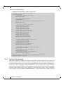
Flow Domains and Priorities
Flow steering defines the concept of domain and priority. Each domain represents a user agent
that can attach a flow. The domains are prioritized. A higher priority domain will always super-
Mellanox Technologies
35
Rev 3.1-1.0.4
Feature Overview and Configuration
sede a lower priority domain when their flow specifications overlap. Setting a lower priority
value will result in higher priority.
In addition to the domain, there is priority within each of the domains. Each domain can have at
most 2^12 priorities in accordance to its needs.
The following are the domains at a descending order of priority:
•
Ethtool
Ethtool domain is used to attach an RX ring, specifically its QP to a specified flow.
Please refer to the most recent ethtool manpage for all the ways to specify a flow.
Examples:
• ethtool –U eth5 flow-type ether dst 00:11:22:33:44:55 loc 5 action 2
All packets that contain the above destination MAC address are to be steered into rx-ring 2 (its
underlying QP), with priority 5 (within the ethtool domain)
• ethtool –U eth5 flow-type tcp4 src-ip 1.2.3.4 dst-port 8888 loc 5 action 2
All packets that contain the above destination IP address and source port are to be steered into rxring 2. When destination MAC is not given, the user's destination MAC is filled automatically.
• ethtool –u eth5
Shows all of ethtool’s steering rule
When configuring two rules with the same priority, the second rule will overwrite the first one, so this
ethtool interface is effectively a table. Inserting Flow Steering rules in the kernel requires support
from both the ethtool in the user space and in kernel (v2.6.28).
MLX4 Driver Support
The mlx4 driver supports only a subset of the flow specification the ethtool API defines. Asking for
an unsupported flow specification will result with an “invalid value” failure.
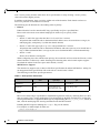
The following are the flow specific parameters:
Table 6 - Flow Specific Parameters
ether
•
Mandatory
dst
Optional
vlan
tcp4/udp4
ip4
src-ip/dst-ip
src-ip, dst-ip, srcport, dst-port, vlan
src-ip, dst-ip, vlan
RFS
RFS is an in-kernel-logic responsible for load balancing between CPUs by attaching flows to CPUs
that are used by flow’s owner applications. This domain allows the RFS mechanism to use the flow
steering infrastructure to support the RFS logic by implementing the ndo_rx_flow_steer, which, in
turn, calls the underlying flow steering mechanism with the RFS domain.
Enabling the RFS requires enabling the ‘ntuple’ flag via the ethtool,
For example, to enable ntuple for eth0, run:
ethtool -K eth0 ntuple on
36
Mellanox Technologies
Rev 3.1-1.0.4
RFS requires the kernel to be compiled with the CONFIG_RFS_ACCEL option. This options is available
in kernels 2.6.39 and above. Furthermore, RFS requires Device Managed Flow Steering support.
RFS cannot function if LRO is enabled. LRO can be disabled via ethtool.
•
All of the rest
The lowest priority domain serves the following users:
• The mlx4 Ethernet driver attaches its unicast and multicast MACs addresses to its QP
using L2 flow specifications
Fragmented UDP traffic cannot be steered. It is treated as 'other' protocol by hardware
(from the first packet) and not considered as UDP traffic.
3.4
Virtualization
3.4.1
Single Root IO Virtualization (SR-IOV)
Single Root IO Virtualization (SR-IOV) is a technology that allows a physical PCIe device to
present itself multiple times through the PCIe bus. This technology enables multiple virtual
instances of the device with separate resources. Mellanox adapters are capable of exposing in
ConnectX®-3 adapter cards up to 126 virtual instances called Virtual Functions (VFs) and ConnectX-4/Connect-IB adapter cards up to 62 virtual instances. These virtual functions can then be
provisioned separately. Each VF can be seen as an additional device connected to the Physical
Function. It shares the same resources with the Physical Function, and its number of ports equals
those of the Physical Function.
SR-IOV is commonly used in conjunction with an SR-IOV enabled hypervisor to provide virtual
machines direct hardware access to network resources hence increasing its performance.
In this chapter we will demonstrate setup and configuration of SR-IOV in a Red Hat Linux environment using Mellanox ConnectX® VPI adapter cards family.
3.4.1.1 System Requirements
To set up an SR-IOV environment, the following is required:
•
MLNX_EN Driver
•
A server/blade with an SR-IOV-capable motherboard BIOS
•
Hypervisor that supports SR-IOV such as: Red Hat Enterprise Linux Server Version 6.*
•
Mellanox ConnectX® VPI Adapter Card family with SR-IOV capability
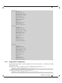
3.4.1.2 Setting Up SR-IOV
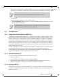
Depending on your system, perform the steps below to set up your BIOS. The figures used in this
section are for illustration purposes only. For further information, please refer to the appropriate
BIOS User Manual:
Mellanox Technologies
37
Rev 3.1-1.0.4
Feature Overview and Configuration
Step 1.
Enable "SR-IOV" in the system BIOS.
Step 2.
Enable "Intel Virtualization Technology".
Step 3.
Install the hypervisor that supports SR-IOV.
Step 4.
Depending on your system, update the /boot/grub/grub.conf file to include a similar command
line load parameter for the Linux kernel.
For example, to Intel systems, add:
default=0
timeout=5
splashimage=(hd0,0)/grub/splash.xpm.gz
hiddenmenu
title Red Hat Enterprise Linux Server (2.6.32-36.x86-645)
root (hd0,0)
kernel /vmlinuz-2.6.32-36.x86-64 ro root=/dev/VolGroup00/LogVol00 rhgb quiet
intel_iommu=ona
initrd /initrd-2.6.32-36.x86-64.img
38
Mellanox Technologies
Rev 3.1-1.0.4
a. Please make sure the parameter "intel_iommu=on" exists when updating the /boot/grub/grub.conf
file, otherwise SR-IOV cannot be loaded.
3.4.1.2.1 Configuring SR-IOV for ConnectX-3/ConnectX-3 Pro
Step 1.
Install the MLNX_OFED driver for Linux that supports SR-IOV.
SR-IOV can be enabled and managed by using one of the following methods:
•
Run the mlxconfig tool and set the SRIOV_EN parameter to “1” without re-burning the firmware
To find the mst device run: “mst start” and “mst status”
mlxconfig -d <mst_device> s SRIOV_EN=1
For further information, please refer to section “mlxconfig - Changing Device Configuration Tool”
in the MFT User Manual (www.mellanox.com > Products > Software > Firmware Tools).
•
Burn firmware with SR-IOV support where the number of virtual functions (VFs) will be set to
16
--enable-sriov
Step 2.
Verify the HCA is configured to support SR-IOV.
# mstflint -dev <PCI Device> dc
1. Verify in the [HCA] section the following fields appear1,2:
[HCA]
num_pfs = 1
total_vfs = <0-126>
sriov_en = true
Parameter
Recommended Value
num_pfs
1
Note: This field is optional and might not always
appear.
total_vfs
• When using firmware version 2.31.5000 and
above, the recommended value is 126.
• When using firmware version 2.30.8000 and
below, the recommended value is 63
Note: Before setting number of VFs in SR-IOV,
please make sure your system can support that
amount of VFs. Setting number of VFs larger than
what your Hardware and Software can support may
cause your system to cease working.
sriov_en
true
2. Add the above fields to the INI if they are missing.
3. Set the total_vfs parameter to the desired number if you need to change the num-
ber of total VFs.
4. Reburn the firmware using the mlxburn tool if the fields above were added to the
INI, or the total_vfs parameter was modified.
1. If SR-IOV is supported, to enable SR-IOV (if it is not enabled), it is sufficient to set “sriov_en = true” in the INI.
2. If the HCA does not support SR-IOV, please contact Mellanox Support: [email protected]
Mellanox Technologies
39
Rev 3.1-1.0.4
Feature Overview and Configuration
If the mlxburn is not installed, please downloaded it from the Mellanox website
http://www.mellanox.com > products > Firmware tools
mlxburn -fw ./fw-ConnectX3-rel.mlx -dev /dev/mst/mt4099_pci_cr0 -conf ./MCX341AXCG_Ax.ini
Step 3.
Create the text file /etc/modprobe.d/mlx4_core.conf if it does not exist.
Step 4.
Insert an "option" line in the /etc/modprobe.d/mlx4_core.conf file to set the number of VFs.
the protocol type per port, and the allowed number of virtual functions to be used by the
physical function driver (probe_vf).
For example:
options mlx4_core num_vfs=5 port_type_array=1,2 probe_vf=1
Parameter
num_vfs
Recommended Value
• If absent, or zero: no VFs will be available
• If its value is a single number in the range of 0-63:
The driver will enable the num_vfs VFs on the HCA
and this will be applied to all ConnectX® HCAs on
the host.
• If its a triplet x,y,z (applies only if all ports are configured as Ethernet) the driver creates:
•
•
x single port VFs on physical port 1
y single port VFs on physical port 2 (applies only if such a
port exist)
• z n-port VFs (where n is the number of physical ports on
device).
This applies to all ConnectX® HCAs on the host
40
Mellanox Technologies
Rev 3.1-1.0.4
Parameter
num_vfs
Recommended Value
• If its format is a string: The string specifies the
num_vfs parameter separately per installed HCA.
The string format is: "bb:dd.f-v,bb:dd.f-v,…"
• bb:dd.f = bus:device.function of the PF of the HCA
• v = number of VFs to enable for that HCA which is either a
single value or a triplet, as described above.
For example:
• num_vfs=5 - The driver will enable 5 VFs on the HCA
and this will be applied to all ConnectX® HCAs on
the host
• num_vfs=00:04.0-5,00:07.0-8 - The driver will
enable 5 VFs on the HCA positioned in BDF 00:04.0
and 8 on the one in 00:07.0)
• num_vfs=1,2,3 - The driver will enable 1 VF on
physical port 1, 2 VFs on physical port 2 and 3 dual
port VFs (applies only to dual port HCA when all
ports are Ethernet ports).
• num_vfs=00:04.0-5;6;7,00:07.0-8;9;10 - The
driver will enable:
•
HCA positioned in BDF 00:04.0
•
•
•
•
5 single VFs on port 1
6 single VFs on port 2
7 dual port VFs
HCA positioned in BDF 00:07.0
•
•
•
8 single VFs on port 1
9 single VFs on port 2
10 dual port VFs
Applies when all ports are configure as Ethernet in dual port
HCAs
Notes:
• PFs not included in the above list will not have SRIOV enabled.
• Triplets and single port VFs are only valid when all
ports are configured as Ethernet. When an InfiniBand
port exists, only num_vfs=a syntax is valid where “a”
is a single value that represents the number of VFs.
• The second parameter in a triplet is valid only when
there are more than 1 physical port.
In a triplet, x+z<=63 and y+z<=63, the maximum number of
VFs on each physical port must be 63.
port_type_array
Specifies the protocol type of the ports. It is either one array
of 2 port types 't1,t2' for all devices or list of BDF to
port_type_array 'bb:dd.f-t1;t2,...'. (string)
Valid port types: 1-ib, 2-eth, 3-auto, 4-N/A
If only a single port is available, use the N/A port type for
port2 (e.g '1,4').
Note that this parameter is valid only when num_vfs is not
zero (i.e., SRIOV is enabled). Otherwise, it is ignored.
Mellanox Technologies
41
Rev 3.1-1.0.4
Feature Overview and Configuration
Parameter
probe_vf
Recommended Value
• If absent or zero: no VF interfaces will be loaded in
the Hypervisor/host
• If num_vfs is a number in the range of 1-63, the driver
running on the Hypervisor will itself activate that
number of VFs. All these VFs will run on the Hypervisor. This number will apply to all ConnectX® HCAs
on that host.
• If its a triplet x,y,z (applies only if all ports are configured as Ethernet), the driver probes:
•
•
•
x single port VFs on physical port 1
y single port VFs on physical port 2 (applies only if such a
port exist)
z n-port VFs (where n is the number of physical ports on
device). Those VFs are attached to the hypervisor.
• If its format is a string: the string specifies the
probe_vf parameter separately per installed HCA.
The string format is: "bb:dd.f-v,bb:dd.f-v,…
• bb:dd.f = bus:device.function of the PF of the HCA
• v = number of VFs to use in the PF driver for that HCA
which is either a single value or a triplet, as described above
For example:
• probe_vfs=5 - The PF driver will activate 5 VFs on
the HCA and this will be applied to all ConnectX®
HCAs on the host
• probe_vfs=00:04.0-5,00:07.0-8 - The PF driver
will activate 5 VFs on the HCA positioned in BDF
00:04.0 and 8 for the one in 00:07.0)
• probe_vf=1,2,3 - The PF driver will activate 1 VF
on physical port 1, 2 VFs on physical port 2 and 3 dual
port VFs (applies only to dual port HCA when all
ports are Ethernet ports).
This applies to all ConnectX® HCAs in the host.
• probe_vf=00:04.0-5;6;7,00:07.0-8;9;10 - The
PF driver will activate:
•
HCA positioned in BDF 00:04.0
•
•
•
•
5 single VFs on port 1
6 single VFs on port 2
7 dual port VFs
HCA positioned in BDF 00:07.0
•
•
•
8 single VFs on port 1
9 single VFs on port 2
10 dual port VFs
Applies when all ports are configure as Ethernet in dual port
HCAs.
42
Mellanox Technologies
Rev 3.1-1.0.4
Parameter
probe_vf
Recommended Value
Notes:
• PFs not included in the above list will not activate any
of their VFs in the PF driver
• Triplets and single port VFs are only valid when all
ports are configured as Ethernet. When an InfiniBand
port exist, only probe_vf=a syntax is valid where “a”
is a single value that represents the number of VFs
• The second parameter in a triplet is valid only when
there are more than 1 physical port
• Every value (either a value in a triplet or a single
value) should be less than or equal to the respective
value of num_vfs parameter
The example above loads the driver with 5 VFs (num_vfs). The standard use of a VF is a single
VF per a single VM. However, the number of VFs varies upon the working mode requirements.
Step 5.
Reboot the server.
If the SR-IOV is not supported by the server, the machine might not come out of boot/
load.
Step 6.
Load the driver and verify the SR-IOV is supported. Run:
lspci |
03:00.0
10GigE]
03:00.1
03:00.2
03:00.3
03:00.4
03:00.5
grep Mellanox
InfiniBand: Mellanox
(rev b0)
InfiniBand: Mellanox
InfiniBand: Mellanox
InfiniBand: Mellanox
InfiniBand: Mellanox
InfiniBand: Mellanox
Technologies MT26428 [ConnectX VPI PCIe 2.0 5GT/s - IB QDR /
Technologies
Technologies
Technologies
Technologies
Technologies
MT27500
MT27500
MT27500
MT27500
MT27500
Family
Family
Family
Family
Family
[ConnectX-3
[ConnectX-3
[ConnectX-3
[ConnectX-3
[ConnectX-3
Virtual
Virtual
Virtual
Virtual
Virtual
Function]
Function]
Function]
Function]
Function]
(rev
(rev
(rev
(rev
(rev
Where:
•
“03:00" represents the Physical Function
•
“03:00.X" represents the Virtual Function connected to the Physical Function
3.4.1.2.2 Configuring SR-IOV for ConnectX-4
Step 1.
Install the MLNX_OFED driver for Linux that supports SR-IOV.
Step 2.
Check if SR-IOV is enabled in the firmware.
mlxconfig -d /dev/mst/mt4115_pciconf0 q
Device #1:
---------Device type:
ConnectX4
PCI device:
/dev/mst/mt4115_pciconf0
Configurations:
Current
SRIOV_EN
1
NUM_OF_VFS
8
FPP_EN
1
Mellanox Technologies
43
b0)
b0)
b0)
b0)
b0)
Rev 3.1-1.0.4
Feature Overview and Configuration
If not, use mlxconfig to enable it.
mlxconfig -d /dev/mst/mt4115_pciconf0 set SRIOV_EN=1 NUM_OF_VFS=16 FPP_EN=1
Step 3.
Either reset or reboot the firmware.
mlxfwreset / reboot
Step 4.
Write to the sysfs file the number of Virtual Functions you need to create for the PF.
You can use one of the following files:
•
A standard Linux kernel generated file that is available in the new kernels.
echo [num_vfs] > /sys/class/net/ethx/device/sriov_numvfs
•
A file generated by the mlx5_core driver with the same functionality as the kernel generated one.
Used by old kernels that do not have the standard file.
echo [num_vfs] > /sys/class/net/ethx/device/mlx5_num_vfs
The following rules apply when writing to these file:
•
If there are no VFs assigned, the number of VFs can be changed to any valid value (0 - max #VFs
as set during FW burning)
•
If there are VFs assigned to a VM, it is not possible to change the number of VFs
•
If the administrator unloads the driver on the PF while there are no VFs assigned, the driver will
unload and SRI-OV will be disabled
•
If there are VFs assigned while the driver of the PF is unloaded, SR-IOV is not be disabled. This
means VFs will be visible on the VM. However they will not be operational.
•
•
Step 5.
The VF driver will discover this situation and will close its resources
When the driver on the PF is reloaded, the VF becomes operational. The administrator of the
VF will need to restart the driver in order to resume working with the VF.
Load the driver and verify the SR-IOV is supported. Run:
lspci | grep Mellanox
08:00.0 Infiniband controller:
08:00.1 Infiniband controller:
08:00.2 Infiniband controller:
Function]
08:00.3 Infiniband controller:
Function]
08:00.4 Infiniband controller:
Function]
08:00.5 Infiniband controller:
Function]
Mellanox Technologies MT27700 Family [ConnectX-4]
Mellanox Technologies MT27700 Family [ConnectX-4]
Mellanox Technologies MT27700 Family [ConnectX-4 Virtual
Mellanox Technologies MT27700 Family [ConnectX-4 Virtual
Mellanox Technologies MT27700 Family [ConnectX-4 Virtual
Mellanox Technologies MT27700 Family [ConnectX-4 Virtual
When SR-IOV is enabled in the PF, the following structure becomes available
at /sys/class/net/ethx/device/sriov
44
Mellanox Technologies
Rev 3.1-1.0.4
+-|
|
|
+-|
|
|
+--
0
+-+-+-1
+-+-+-2
+-+-+--
node
policy
port
node
policy
port
node
policy
port
In the extract above we see three Virtual Functions numbered 0 to 2. For each Virtual
Function we have the following files:
•
Node stands for node GUID: The user can set the node GUID of the VF by writing to this file.
•
Port stands for port GUID: The user can set the port GUID of the VF by writing to this file.
•
Policy: The user can read or modify the vport policy.
•
Policy can be one of:
•
Down - the VPort PortState always remains 'Down'
•
Up - if the current VPort PortState is 'Down', it is modified to 'Initialize'. In all other states,
it is unmodified. The result is that the SM may bring the VPort up.
•
•
Follow - follows the PortState of the physical port. If the PortState of the physical port is
'Active', then the VPort implements the 'Up' policy. Otherwise, the VPort PortState is
'Down'.
The policy of all the vports is initialized to Down after restart of the PF driver.
•
An exception is vport0 which for which the policy is modified to Follow by the PF driver
3.4.1.2.3 Note on VFs Initialization
Since the same mlx5_core driver supports both Physical and Virtual Functions, once the Virtual
Functions are created, the driver of the PF will attempt to initialize them so they will be available
to the OS owning the PF. If you want to assign a Virtual Function to a VM, you need to make
sure the VF is not used by the PF driver. If a VF is used, you should first unbind it before assigning to a VM.
To unbind a device use the following command:
1. Get the full PCI address of the device.
lspci -D
Example:
0000:09:00.2
2. Unbind the device.
echo 0000:09:00.2 > /sys/bus/pci/drivers/mlx5_core/unbind
3. Bind the unbound VF.
echo 0000:09:00.2 > /sys/bus/pci/drivers/mlx5_core/bind
Mellanox Technologies
45
Rev 3.1-1.0.4
Feature Overview and Configuration
3.4.1.3 Enabling SR-IOV and Para Virtualization on the Same Setup
To enable SR-IOV and Para Virtualization on the same setup:
Step 1.
Create a bridge.
vim /etc/sysconfig/network-scripts/ifcfg-bridge0
DEVICE=bridge0
TYPE=Bridge
IPADDR=12.195.15.1
NETMASK=255.255.0.0
BOOTPROTO=static
ONBOOT=yes
NM_CONTROLLED=no
DELAY=0
Step 2.
Change the related interface (in the example below bridge0 is created over eth5).
DEVICE=eth5
BOOTPROTO=none
STARTMODE=on
HWADDR=00:02:c9:2e:66:52
TYPE=Ethernet
NM_CONTROLLED=no
ONBOOT=yes
BRIDGE=bridge0
Step 3.
Restart the service network.
Step 4.
Attach a virtual NIC to VM.
ifconfig -a
…
eth6
Link encap:Ethernet HWaddr 52:54:00:E7:77:99
inet addr:13.195.15.5 Bcast:13.195.255.255 Mask:255.255.0.0
inet6 addr: fe80::5054:ff:fee7:7799/64 Scope:Link
UP BROADCAST RUNNING MULTICAST MTU:1500 Metric:1
RX packets:481 errors:0 dropped:0 overruns:0 frame:0
TX packets:450 errors:0 dropped:0 overruns:0 carrier:0
collisions:0 txqueuelen:1000
RX bytes:22440 (21.9 KiB) TX bytes:19232 (18.7 KiB)
Interrupt:10 Base address:0xa000
…
46
Mellanox Technologies
Rev 3.1-1.0.4
Step 5.
Add the MAC 52:54:00:E7:77:99 to the /sys/class/net/eth5/fdb table on HV.
Before:
cat /sys/class/net/eth5/fdb
33:33:00:00:02:02
33:33:ff:2e:66:52
01:00:5e:00:00:01
33:33:00:00:00:01
Do:
echo "+52:54:00:E7:77:99" > /sys/class/net/eth5/fdb
After:
cat /sys/class/net/eth5/fdb
52:54:00:e7:77:99
33:33:00:00:02:02
33:33:ff:2e:66:52
01:00:5e:00:00:01
33:33:00:00:00:01…
3.4.1.4 Assigning a Virtual Function to a Virtual Machine
This section will describe a mechanism for adding a SR-IOV VF to a Virtual Machine.
3.4.1.4.1 Assigning the SR-IOV Virtual Function to the Red Hat KVM VM Server
Step 1.
Run the virt-manager.
Step 2.
Double click on the virtual machine and open its Properties.
Step 3.
Go to Details->Add hardware ->PCI host device.
Step 4.
Choose a Mellanox virtual function according to its PCI device (e.g., 00:03.1)
Step 5.
If the Virtual Machine is up reboot it, otherwise start it.
Step 6.
Log into the virtual machine and verify that it recognizes the Mellanox card. Run:
lspci | grep Mellanox
00:03.0 InfiniBand: Mellanox Technologies MT27500 Family [ConnectX-3 Virtual Function] (rev b0)
Mellanox Technologies
47
Rev 3.1-1.0.4
Feature Overview and Configuration
Step 7.
Add the device to the /etc/sysconfig/network-scripts/ifcfg-ethX configuration file. The
MAC address for every virtual function is configured randomly, therefore it is not necessary to
add it.
3.4.1.5 Uninstalling SR-IOV Driver
To uninstall SR-IOV driver, perform the following:
Step 1.
For Hypervisors, detach all the Virtual Functions (VF) from all the Virtual Machines (VM) or
stop the Virtual Machines that use the Virtual Functions.
Please be aware, stopping the driver when there are VMs that use the VFs, will cause machine to hang.
Step 2.
Run the script below. Please be aware, uninstalling the driver deletes the entire driver's file, but
does not unload the driver.
# /sbin/mlnx_en_uninstall.sh
MLNX_EN uninstall done
Step 3.
Restart the server.
3.4.1.6 Ethernet Virtual Function Configuration when Running SR-IOV
3.4.1.6.1 VLAN Guest Tagging (VGT) and VLAN Switch Tagging (VST)
When running ETH ports on VFs, the ports may be configured to simply pass through packets as
is from VFs (Vlan Guest Tagging), or the administrator may configure the Hypervisor to silently
force packets to be associated with a VLan/Qos (Vlan Switch Tagging).
In the latter case, untagged or priority-tagged outgoing packets from the guest will have the
VLAN tag inserted, and incoming packets will have the VLAN tag removed. Any vlan-tagged
packets sent by the VF are silently dropped. The default behavior is VGT.
The feature may be controlled on the Hypervisor from userspace via iprout2 / netlink:
ip link set { dev DEVICE | group DEVGROUP } [ { up | down } ]
...
[ vf NUM [ mac LLADDR ]
[ vlan VLANID [ qos VLAN-QOS ] ]
...
[ spoofchk { on | off} ] ]
[ state { auto | enable | disable} ] ]
...
use:
ip link set dev <PF device> vf <NUM> vlan <vlan_id> [qos <qos>]
•
where NUM = 0..max-vf-num
•
vlan_id = 0..4095 (4095 means "set VGT")
•
qos = 0..7
For example:
•
ip link set dev eth2 vf 2 qos 3 -
sets VST mode for VF #2 belonging to PF eth2,
with qos = 3
•
48
ip link set dev eth2 vf 4095
Mellanox Technologies
- sets mode for VF 2 back to VGT
Rev 3.1-1.0.4
3.4.1.6.2 Additional Ethernet VF Configuration Options
•
Guest MAC configuration
By default, guest MAC addresses are configured to be all zeroes. In the MLNX_EN guest driver,
if a guest sees a zero MAC, it generates a random MAC address for itself. If the administrator wishes
the guest to always start up with the same MAC, he/she should configure guest MACs before the
guest driver comes up.
The guest MAC may be configured by using:
ip link set dev <PF device> vf <NUM> mac <LLADDR>
For legacy guests, which do not generate random MACs, the adminstrator should always configure
their MAC addresses via ip link, as above.
•
Spoof checking
Spoof checking is currently available only on upstream kernels newer than 3.1.
ip link set dev <PF device> vf <NUM> spoofchk [on | off]
•
Link State
VF link state can be configured to one of the following 3 options: auto, enable, disable.
ip link set dev <PF device> vf <NUM> state [auto | enable | disable]
3.4.1.6.3 Mapping VFs to Ports using the mlnx_get_vfs.pl Tool
To map the PCI representation in BDF to the respective ports:
mlnx_get_vfs.pl
The output is as following:
BDF 0000:04:00.0
Port 1: 2
vf0
vf1
Port 2: 2
vf2
vf3
Both: 1
vf4
0000:04:00.1
0000:04:00.2
0000:04:00.3
0000:04:00.4
0000:04:00.5
3.4.1.7 MAC Forwarding DataBase (FDB) Management
3.4.1.7.1 FDB Status Reporting
FDB also know as Forwarding Information Base (FIB) or the forwarding table, is most commonly used in network bridging, routing, and similar functions to find the proper interface to
which the input interface should forward a packet.
In the SR-IOV environment, the Ethernet driver can share the existing 128 MACs (for each port)
among the Virtual interfaces (VF) and Physical interfaces (PF) that share the same table as follow:
•
Each VF gets 2 granted MACs (which are taken from the general pool of the 128 MACs)
•
Each VF/PF can ask for up to 128 MACs on the policy of first-asks first-served (meaning, except for the 2 granted MACs, the other MACs in the pool are free to be asked)
Mellanox Technologies
49
Rev 3.1-1.0.4
Feature Overview and Configuration
To check if there are free MACs for its interface (PF or VF), run: /sys/class/net/<ethX>/
fdb_det.
50
Mellanox Technologies
Rev 3.1-1.0.4
Example:
cat /sys/class/net/eth2/fdb_det
device eth2: max: 112, used: 2, free macs: 110
To add a new MAC to the interface:
echo +<MAC> > /sys/class/net/eth<X>/fdb
Once running the command above, the interface (VF/PF) verifies if a free MAC exists. If there
is a free MAC, the VF/PF takes it from the global pool and allocates it. If there is no free MAC,
an error is returned notifying the user of lack of MACs in the pool.
To delete a MAC from the interface:
echo -<MAC> > /sys/class/net/eth<X>/fdb
If /sys/class/net/eth<X>/fdb does not exist, use the Bridge tool from the ip-route2 package
which includes the tool to manage FDB tables as the kernel supports FDB callbacks:
bridge fdb add 00:01:02:03:04:05 permanent self dev p3p1
bridge fdb del 00:01:02:03:04:05 permanent self dev p3p1
bridge fdb show dev p3p1
If adding a new MAC from the kernel's NDO function fails due to insufficient MACs in
the pool, the following error flow will occur:
• If the interface is a PF, it will automatically enter the promiscuous mode
• If the interface is a VF, it will try to enter the promiscuous mode and since it does not
support it, the action will fail and an error will be printed in the kernel’s log
Mellanox Technologies
51
Rev 3.1-1.0.4
3.4.2
Feature Overview and Configuration
VXLAN Hardware Stateless Offloads
VXLAN technology introduced for solving scalability and security challenges, requires extension of the traditional stateless offloads to avoid performance drop. ConnectX-3 Pro adapter card
offers the following stateless offloads for a VXLAN packet, similar to the ones offered to nonencapsulated packets. VXLAN protocol encapsulates its packets using outer UDP header.
Available hardware stateless offloads:
•
Checksum generation (Inner IP and Inner TCP/UDP)
•
Checksum validation (Inner IP and Inner TCP/UDP). This will allow the use of GRO for
inner TCP packets.
•
TSO support for inner TCP packets
•
RSS distribution according to inner packets attributes
•
Receive queue selection - inner frames may be steered to specific QPs
3.4.2.1 Prerequisites
•
HCA: ConnectX-3 Pro
•
Firmware 2.32.5100 or higher
•
RHEL7, Ubuntu 14.04 or upstream kernel 3.12.10 (or higher)
•
DMFS enabled
•
A0 static mode disabled
3.4.2.2 Enabling VXLAN Hardware Stateless Offloads
To enable the VXLAN offloads support load the mlx4_core driver with Device-Managed Flowsteering (DMFS) enabled. DMFS is the default steering mode.
To verify it is enabled by the adapter card:
Step 1.
Open the /etc/modprobe.d/mlnx.conf file.
Step 2.
Set the parameter debug_level to “1”.
options mlx4_core debug_level=1
Step 3.
Restart the driver.
Step 4.
Verify in the dmesg that the tunneling mode is: vxlan.
The net-device will advertise the tx-udp-tnl-segmentation flag shown when running "ethtonly when VXLAN is configured in the OpenvSwitch (OVS) with
the configured UDP port.
hool -k $DEV | grep udp"
For example:
$ ethtool -k eth0 | grep udp_tnl
tx-udp_tnl-segmentation: on
As of firmware version 2.31.5050, VXLAN tunnel can be set on any desired UDP port. If using
previous firmware versions, set the VXLAN tunnel over UDP port 4789.
To add the UDP port to /etc/modprobe.d/vxlan.conf:
options vxlan udp_port=<number decided above>
52
Mellanox Technologies
Rev 3.1-1.0.4
3.4.2.3 Important Notes
•
VXLAN tunneling adds 50 bytes (14-eth + 20-ip + 8-udp + 8-vxlan) to the VM Ethernet
frame. Please verify that either the MTU of the NIC who sends the packets, e.g. the VM
virtio-net NIC or the host side veth device or the uplink takes into account the tunneling
overhead. Meaning, the MTU of the sending NIC has to be decremented by 50 bytes
(e.g 1450 instead of 1500), or the uplink NIC MTU has to be incremented by 50 bytes
(e.g 1550 instead of 1500)
•
From upstream 3.15-rc1 and onward, it is possible to use arbitrary UDP port for
VXLAN. Note that this requires firmware version 2.31.2800 or higher. Additionally, you
need to enable this kernel configuration option CONFIG_MLX4_EN_VXLAN=y.
•
On upstream kernels 3.12/3.13 GRO with VXLAN is not supported
3.5
Resiliency
3.5.1
Reset Flow
Supported in ConnectX-3 and ConnectX-3 Pro only.
Reset Flow is activated by default, once a "fatal device1" error is recognized. Both the HCA and
the software are reset, the ULPs and user application are notified about it, and a recovery process
is performed once the event is raised. The "Reset Flow" is activated by the mlx4_core module
parameter 'internal_err_reset', and its default value is 1.
3.5.1.1 Kernel ULPs
Once a "fatal device" error is recognized, an IB_EVENT_DEVICE_FATAL event is created, ULPs are
notified about the incident, and outstanding WQEs are simulated to be returned with "flush in
error" message to enable each ULP to close its resources and not get stuck via calling its
"remove_one" callback as part of "Reset Flow".
Once the unload part is terminated, each ULP is called with its "add_one" callback, its resources
are re-initialized and it is re-activated.
3.5.1.2 SR-IOV
If the Physical Function recognizes the error, it notifies all the VFs about it by marking their
communication channel with that information, consequently, all the VFs and the PF are reset.
If the VF encounters an error, only that VF is reset, whereas the PF and other VFs continue to
work unaffected.
3.5.1.3 Forcing the VF to Reset
If an outside "reset" is forced by using the PCI sysfs entry for a VF, a reset is executed on that VF
once it runs any command over its communication channel.
1. A “fatal device” error can be a timeout from a firmware command, an error on a firmware closing command, communication channel not being
responsive in a VF. etc.
Mellanox Technologies
53
Rev 3.1-1.0.4
Feature Overview and Configuration
For example, the below command can be used on a hypervisor to reset a VF defined by
0000\:04\:00.1:
echo 1 >/sys/bus/pci/devices/0000\:04\:00.1/reset
3.5.1.4 Advanced Error Reporting (AER)
AER, a mechanism used by the driver to get notifications upon PCI errors, is supported only in
native mode, ULPs are called with remove_one/add_one and expect to continue working properly after that flow.User space application will work in same mode as defined in the "Reset Flow"
above.
3.5.1.5 Extended Error Handling (EEH)
Extended Error Handling (EEH) is a PowerPC mechanism that encapsulates AER, thus exposing
AER events to the operating system as EEH events.
The behavior of ULPs and user space applications is identical to the behavior of AER.
3.6
Ignore Frame Check Sequence (FCS) Errors
Supported in ConnectX-3 Pro and ConnectX-4 only.
Upon receiving packets, the packets go through a checksum validation process for the FCS field.
If the validation fails, the received packets are dropped.
When FCS is enabled (disabled by default), the device does not validate the FCS field even if the
field is invalid.
It is not recommended to enable FCS.
For further information on how to enable/disable FCS, please refer to Table 7, “ethtool Supported
Options,” on page 55
3.7
Ethtool
ethtool is a standard Linux utility for controlling network drivers and hardware, particularly for
wired Ethernet devices. It can be used to:
54
•
Get identification and diagnostic information
•
Get extended device statistics
•
Control speed, duplex, autonegotiation and flow control for Ethernet devices
•
Control checksum offload and other hardware offload features
•
Control DMA ring sizes and interrupt moderation
Mellanox Technologies
Rev 3.1-1.0.4
The following are the ethtool supported options:
Table 7 - ethtool Supported Options
Options
ethtool -i eth<x>
Description
Checks driver and device information.
For example:
#> ethtool -i eth2
driver: mlx4_en (MT_0DD0120009_CX3)
version: 2.1.6 (Aug 2013)
firmware-version: 2.30.3000
bus-info: 0000:1a:00.0
ethtool -k eth<x>
Queries the stateless offload status.
ethtool -c eth<x>
Queries interrupt coalescing settings.
ethtool -C eth<x> adaptive-rx
on|off
Note: Supported in ConnectX®-3/ConnectX®-3 Pro cards
only.
Enables/disables adaptive interrupt moderation.
By default, the driver uses adaptive interrupt moderation for
the receive path, which adjusts the moderation time to the
traffic pattern.
For further information, please refer to Adaptive Interrupt
Moderation section.
ethtool -C eth<x> [pkt-rate-low N]
[pkt-rate-high N] [rx-usecs-low N]
[rx-usecs-high N]
Note: Supported in ConnectX®-3/ConnectX®-3 Pro cards
only.
Sets the values for packet rate limits and for moderation
time high and low values.
For further information, please refer to Adaptive Interrupt
Moderation section.
ethtool -C eth<x> [rx-usecs N] [rxframes N]
Sets the interrupt coalescing setting.
rx-frames will be enforced immediately, rx-usecs will be
enforced only when adaptive moderation is disabled.
Note: usec settings correspond to the time to wait after the
*last* packet is sent/received before triggering an interrupt.
Mellanox Technologies
55
Rev 3.1-1.0.4
Feature Overview and Configuration
Table 7 - ethtool Supported Options
Options
ethtool -K eth<x> [rx on|off] [tx
on|off] [sg on|off] [tso on|off] [lro
on|off] [gro on|off] [gso on|off]
[rxvlan on|off] [txvlan on|off] [ntuple on/off] [rxhash on/off] [rx-all
on/off] [rx-fcs on/off]
Description
Sets the stateless offload status.
TCP Segmentation Offload (TSO), Generic Segmentation
Offload (GSO): increase outbound throughput by reducing
CPU overhead. It works by queuing up large buffers and letting the network interface card split them into separate
packets.
Large Receive Offload (LRO): increases inbound throughput of high-bandwidth network connections by reducing
CPU overhead. It works by aggregating multiple incoming
packets from a single stream into a larger buffer before they
are passed higher up the networking stack, thus reducing the
number of packets that have to be processed. LRO is available in kernel versions < 3.1 for untagged traffic.
Hardware VLAN insertion Offload (txvlan): When enabled,
the sent VLAN tag will be inserted into the packet by the
hardware.
Note: LRO will be done whenever possible. Otherwise
GRO will be done. Generic Receive Offload (GRO) is
available throughout all kernels.
Hardware VLAN Striping Offload (rxvlan): When enabled
received VLAN traffic will be stripped from the VLAN tag
by the hardware.
RX FCS (rx-fcs): Keeps FCS field in the received packets.
RX FCS validation (rx-all): Ignores FCS validation on the
received packets.
Note:
The flags below are supported in ConnectX®-3/ConnectX®-3 Pro cards only:
[rxvlan on|off] [txvlan on|off] [ntuple on/off]
[rxhash on/off] [rx-all on/off] [rx-fcs on/off]
ethtool -a eth<x>
Note: Supported in ConnectX®-3/ConnectX®-3 Pro cards
only.
Queries the pause frame settings.
ethtool -A eth<x> [rx on|off] [tx
on|off]
Note: Supported in ConnectX®-3/ConnectX®-3 Pro cards
only.
Sets the pause frame settings.
56
ethtool -g eth<x>
Queries the ring size values.
ethtool -G eth<x> [rx <N>] [tx
<N>]
Modifies the rings size.
Mellanox Technologies
Rev 3.1-1.0.4
Table 7 - ethtool Supported Options
Options
Description
ethtool -p|--identify eth<x> <LED
duration>
Allows users to identify interface's physical port by turning
the ports LED on for a number of seconds.
Note: The limit for the LED duration is 65535 seconds.
ethtool -S eth<x>
Obtains additional device statistics.
ethtool -t eth<x>
Performs a self diagnostics test.
ethtool -s eth<x> msglvl [N]
Changes the current driver message level.
ethtool -T eth<x>
Note: Supported in ConnectX®-3/ConnectX®-3 Pro cards
only.
Shows time stamping capabilities
ethtool -l eth<x>
Shows the number of channels
ethtool -L eth<x> [rx <N>] [tx
<N>]
Sets the number of channels
etthtool -m|--dump-moduleeeprom eth<x> [ raw on|off ] [ hex
on|off ] [ offset N ] [ length N ]
Queries/Decodes the cable module eeprom information.
ethtool --show-priv-flags eth<x>
Shows driver private flags and their states (ON/OFF)
Note: For ConnectX®-4 cards, use ethtool -L eth<x>
combined <N> to set both RX and TX channels.
The private flag is:
• qcn_disable_32_14_4_e
The flags below indicate the flow steering current configuration and limits.
• mlx4_flow_steering_ethernet_l2
• mlx4_flow_steering_ipv4
• mlx4_flow_steering_tcp
For further information, refer to Flow Steering section.
The flags below are related to Ignore Frame Check
Sequence, and they are active when ethtool -k does not
support them:
• orx-fcs
• orx-all
ethtool --set-priv-flags eth<x>
<priv flag> <on/off>
Enables/disables driver feature matching the given private
flag.
ethtool -s eth<x> speed <SPEED>
autoneg off
Changes the link speed to requested <SPEED>. To check
the supported speeds, run ethtool eth<x>.
NOTE: <autoneg off> does not set autoneg OFF, it only
hints the driver to set a specific speed.
Mellanox Technologies
57
Rev 3.1-1.0.4
Feature Overview and Configuration
Table 7 - ethtool Supported Options
Options
ethtool -s eth<x> advertise <N>
autoneg on
Description
Changes the advertised link modes to requested link modes
<N>
To check the link modes’ hex values, run <man ethtool>
and to check the supported link modes, run ethtoo eth<x>
NOTE: <autoneg on> only sends a hint to the driver that
the user wants to modify advertised link modes and not
speed.
3.8
ethtool -X eth<x> equal a b c...
Sets the receive flow hash indirection table.
ethtool -x eth<x>
Retrieves the receive flow hash indirection table.
Checksum Offload
MLNX_EN supports the following Receive IP/L4 Checksum Offload modes:
•
CHECKSUM_UNNECESSARY: By setting this mode the driver indicates to the Linux
Networking Stack that the hardware successfully validated the IP and L4 checksum so
the Linux Networking Stack does not need to deal with IP/L4 Checksum validation.
Checksum Unnecessary is passed to the OS when all of the following are true:
• Ethtool -k <DEV> shows rx-checksumming: on
• Received TCP/UDP packet and both IP checksum and L4 protocol checksum are correct.
•
[ConnectX-3/ConnectX-3 Pro] CHECKSUM_COMPLETE: When the checksum validation cannot be done or fails, the driver still reports to the OS the calculated by hardware checksum value. This allows accelerating checksum validation in Linux
Networking Stack, since it does not have to calculate the whole checksum including payload by itself.
Checksum Complete is passed to OS when all of the following are true:
• Ethtool -k <DEV> shows rx-checksumming: on
• Using ConnectX®-3, firmware version 2.31.7000 and up
• Received IpV4/IpV6 non TCP/UDP packet
The ingress parser of the ConnectX®-3-Pro card comes by default without checksum
offload support for non TCP/UDP packets.
To change that, please set the value of the module parameter ingress_parser_mode
in mlx4_core to 1.
In this mode IPv4/IPv6 non TCP/UDP packets will be passed up to the protocol stack
with CHECKSUM_COMPLETE tag.
In this mode of the ingress parser, the following features are unavailable:
• NVGRE stateless offloads
• VXLAN stateless offloads
• RoCE v2 (R-RoCE over UDP)
Change the default behavior only if non tcp/udp is very common.
58
Mellanox Technologies
Rev 3.1-1.0.4
•
CHECKSUM_NONE: By setting this mode the driver indicates to the Linux Networking Stack that the hardware failed to validate the IP or L4 checksum so the Linux Networking Stack must calculate and validate the IP/L4 Checksum.
Checksum None is passed to OS for all other cases.
3.9
Quantized Congestion Control
Supported in ConnectX-3 and ConnectX-3 Pro only.
Congestion control is used to reduce packet drops in lossy environments and mitigate congestion
spreading and resulting victim flows in lossless environments.
The Quantized Congestion Notification (QCN) IEEE standard (802.1Qau) provides congestion
control for long-lived flows in limited bandwidth-delay product Ethernet networks. It is part of
the IEEE Data Center Bridging (DCB) protocol suite, which also includes ETS, PFC, and
DCBX. QCN in conducted at L2, and is targeted for hardware implementations. QCN applies to
all Ethernet packets and all transports, and both the host and switch behavior is detailed in the
standard.
QCN user interface allows the user to configure QCN activity. QCN configuration and retrieval
of information is done by the mlnx_qcn tool. The command interface provides the user with a set
of changeable attributes, and with information regarding QCN's counters and statistics. All
parameters and statistics are defined per port and priority. QCN command interface is available if
and only the hardware supports it.
3.9.1
QCN Tool - mlnx_qcn
mlnx_qcn is a tool used to configure QCN attributes of the local host. It communicates directly
with the driver thus does not require setting up a DCBX daemon on the system.
The mlnx_qcn enables the user to:
•
Inspect the current QCN configurations for a certain port sorted by priority
•
Inspect the current QCN statistics and counters for a certain port sorted by priority
•
Set values of chosen QCN parameters
Usage:
mlnx_qcn -i <interface> [options]
Options:
--version
-h, --help
-i INTF, --interface=INTF
-g TYPE, --get_type=TYPE
Show program's version number and exit
Show this help message and exit
Interface name
Type of information to get statistics/parameters
Mellanox Technologies
59
Rev 3.1-1.0.4
Feature Overview and Configuration
--rpg_enable=RPG_ENABLE_LIST
--rppp_max_rps=RPPP_MAX_RPS_LIST
--rpg_time_reset=RPG_TIME_RESET_LIST
--rpg_byte_reset=RPG_BYTE_RESET_LIST
--rpg_threshold=RPG_THRESHOLD_LIST
--rpg_max_rate=RPG_MAX_RATE_LIST
--rpg_ai_rate=RPG_AI_RATE_LIST
--rpg_hai_rate=RPG_HAI_RATE_LIST
--rpg_gd=RPG_GD_LIST
--rpg_min_dec_fac=RPG_MIN_DEC_FAC_LIST
--rpg_min_rate=RPG_MIN_RATE_LIST
--cndd_state_machine=CNDD_STATE_MACHINE_LIST
Set value of rpg_enable according to priority, use spaces between values and -1 for
unknown values.
Set value of rppp_max_rps according to priority, use spaces between values and -1 for
unknown values.
Set value of rpg_time_reset according to priority, use spaces between values and -1 for
unknown values.
Set value of rpg_byte_reset according to priority, use spaces between values and -1 for
unknown values.
Set value of rpg_threshold according to priority, use spaces between values and -1 for
unknown values.
Set value of rpg_max_rate according to priority, use spaces between values and -1 for
unknown values.
Set value of rpg_ai_rate according to priority, use spaces between values and -1 for
unknown values.
Set value of rpg_hai_rate according to priority, use spaces between values and -1 for
unknown values.
Set value of rpg_gd according to priority,
use spaces between values and -1 for unknown
values.
Set value of rpg_min_dec_fac according to
priority, use spaces between values and -1
for unknown values.
Set value of rpg_min_rate according to priority, use spaces between values and -1 for
unknown values.
Set value of cndd_state_machine according to
priority, use spaces between values and -1
for unknown values.
To get QCN current configuration sorted by priority:
mlnx_qcn -i eth2 -g parameters
To show QCN's statistics sorted by priority:
mlnx_qcn -i eth2 -g statistics
Example output when running mlnx_qcn -i eth2 -g parameters:
60
Mellanox Technologies
Rev 3.1-1.0.4
priority 0:
rpg_enable: 0
rppp_max_rps: 1000
rpg_time_reset: 1464
rpg_byte_reset: 150000
rpg_threshold: 5
rpg_max_rate: 40000
rpg_ai_rate: 10
rpg_hai_rate: 50
rpg_gd: 8
rpg_min_dec_fac: 2
rpg_min_rate: 10
cndd_state_machine: 0
priority 1:
rpg_enable: 0
rppp_max_rps: 1000
rpg_time_reset: 1464
rpg_byte_reset: 150000
rpg_threshold: 5
rpg_max_rate: 40000
rpg_ai_rate: 10
rpg_hai_rate: 50
rpg_gd: 8
rpg_min_dec_fac: 2
rpg_min_rate: 10
cndd_state_machine: 0
.............................
.............................
priority 7:
rpg_enable: 0
rppp_max_rps: 1000
rpg_time_reset: 1464
rpg_byte_reset: 150000
rpg_threshold: 5
rpg_max_rate: 40000
rpg_ai_rate: 10
rpg_hai_rate: 50
rpg_gd: 8
rpg_min_dec_fac: 2
rpg_min_rate: 10
cndd_state_machine: 0
3.9.2
Setting QCN Configuration
Setting the QCN parameters, requires updating its value for each priority. '-1' indicates no change
in the current value.
Example for setting 'rp g_enable' in order to enable QCN for priorities 3, 5, 6:
mlnx_qcn -i eth2 --rpg_enable=-1 -1 -1 1 -1 1 1 -1
Example for setting 'rpg_hai_rate' for priorities 1, 6, 7:
mlnx_qcn -i eth2 --rpg_hai_rate=60 -1 -1 -1 -1 -1 60 60
Mellanox Technologies
61
Rev 3.1-1.0.4
3.10
Feature Overview and Configuration
Explicit Congestion Notification (ECN)
3.10.1 ConnectX-3/ConnectX-3 Pro ECN
ECN is an extension to the IP protocol. It allows reliable communication by notifying all ends of
communication when a congestion occurs.
This is done without dropping packets. Please note that since this feature requires all nodes in the
path (nodes, routers etc) between the communicating nodes to support ECN to ensure reliable
communication. ECN is marked as 2 bits in the traffic control IP header.
This ECN implementation refers to both RoCE and RoCEv2.
ECN command interface is use to configure ECN activity. The access to it is through the file system (mount of debugfs is required). The interface provides a set of changeable attributes, and
information regarding ECN's counters and statistics.
Enabling the ECN command interface is done by setting the en_ecn module parameter of mlx4_ib to 1:
options mlx4_ib en_ecn=1
3.10.1.1 Enabling ECN
To enable ECN on the hosts
Step 1.
Enable ECN in sysfs.
/proc/sys/net/ipv4/tcp_ecn = 1
Step 2.
Enable ECN CLI.
options mlx4_ib en_ecn=1
Step 3.
Restart the driver.
/etc/init.d/openibd restart
Step 4.
Mount debugfs to access ECN attributes.
mount -t debugfs none /sys/kernel/debug/
Please note, mounting of debugfs is required.
The following is an example for ECN configuration through debugfs (echo 1 to enable attribute):
/sys/kernel/debug/mlx4_ib/<device>/ecn/<algo>/ports/1/params/prios/<prio>/<the
requested attribute>
ECN supports the following algorithms:
•
r_roce_ecn_rp
•
r_roce_ecn_np
Each algorithm has a set of relevant parameters and statistics, which are defined per device, per
port, per priority.
r_roce_ecn_np
has an extra set of general parameters which are defined per device.
ECN and QCN are not compatible. When using ECN, QCN (and all its related daemons/utilities that could enable it, i.e - lldpad) should be turned OFF.
62
Mellanox Technologies
Rev 3.1-1.0.4
3.10.1.2 Various ECN Paths
The following are the paths to ECM algorithm, general parameters and counters.
•
The path to an algorithm attribute is (except for general parameters):
/sys/kernel/debug/mlx4_ib/{DEVICE}/ ecn/{algorithm}/ports/{port}/params/prios/{prio}/
{attribute}
•
The path to a general parameter is:
/sys/kernel/debug/mlx4_ib/{DEVICE}/ ecn/r_roce_ecn_np/gen_params/{attribute}
•
The path to a counter is:
/sys/kernel/debug/mlx4_ib/{DEVICE}/ ecn/{algorithm}/ports/{port}/statistics/prios/
{prio}/{counter}
3.10.2 ConnectX-4 ECN
ECN in ConnectX-4 enables end-to-end congestions notifications between two end-points when
a congestion occurs, and works over Layer 3. ECN must be enabled on all nodes in the path
(nodes, routers etc) between the two end points and the intermediate devices (switches) between
them to ensure reliable communication.
3.10.2.1 Enabling ECN
To enable ECN on the hosts
Step 1.
Enable ECN in sysfs.
/sys/class/net/<interface>/<protocol>/ecn_<protocol>_enable =1
Step 2.
Query the attribute.
cat /sys/class/net/<interface>/ecn/<protocol>/params/<requested attribute>
Step 3.
Modify the attribute.
echo <value> /sys/class/net/<interface>/ecn/<protocol>/params/<requested attribute>
ECN supports the following algorithms:
•
r_roce_ecn_rp - Reaction point
•
r_roce_ecn_np - Notification point
Each algorithm has a set of relevant parameters and statistics, which are defined per device, per
port, per priority.
To query ECN enable per Priority X:
cat /sys/class/net/<interface>/ecn/<protocol>/enable/X
To read ECN configurable parameters:
cat /sys/class/net/<interface>/ecn/<protocol>/requested attributes
To enabled ECN for each priority per protocol:
echo 1 > /sys/class/net/<interface>/ecn/<protocol>/enable/X
To modify ECN configurable parameters:
echo <value> > /sys/class/net/<interface>/ecn/<protocol>/requested attributes
Where:
•
X: priority {0..7}
Mellanox Technologies
63
Rev 3.1-1.0.4
3.11
Feature Overview and Configuration
•
protocol: roce_rp / roce_np
•
requested attributes: Next Slide for each protocol.
XOR RSS Hash Function
The device has the ability to use XOR as the RSS distribution function, instead of the default
Toplitz function.
The XOR function can be better distributed among driver's receive queues in small number of
streams, where it distributes each TCP/UDP stream to a different queue.
MLNX_EN v2.2-1.0.0 and onwards provides an option to change the working RSS hash function
from Toplitz to XOR (and vice versa) through ethtool priv-flags.
For further information, please refer to Table 7, “ethtool Supported Options,” on page 55.
This is the default behavior when using ConnectX®-4 adapter cards and it cannot be changed.
3.12
Ethernet Performance Counters
Supported in ConnectX-3 and ConnectX-3 Pro only.
Counters are used to provide information about how well an operating system, an application, a
service, or a driver is performing. The counter data helps determine system bottlenecks and finetune the system and application performance. The operating system, network, and devices provide counter data that an application can consume to provide users with a graphical view of how
well the system is performing.
The counter index is a QP attribute given in the QP context. Multiple QPs may be associated with
the same counter set, If multiple QPs share the same counter its value represents the cumulative
total.
•
ConnectX®-3 support 127 different counters which allocated:
• 4 counters reserved for PF - 2 counters for each port
• 2 counters reserved for VF - 1 counter for each port
• All other counters if exist are allocated by demand
•
RoCE counters are available only through sysfs located under:
• # /sys/class/infiniband/mlx4_*/ports/*/counters/
• # /sys/class/infiniband/mlx4_*/ports/*/counters_ext/
•
Physical Function can also read Virtual Functions' port counters through sysfs located
under:
• # /sys/class/net/eth*/vf*_statistics/
To display the network device Ethernet statistics, you can run:
Ethtool -S <devname>
Counter
rx_packets
64
Mellanox Technologies
Description
Total packets successfully received.
Rev 3.1-1.0.4
Counter
Description
rx_bytes
Total bytes in successfully received packets.
rx_multicast_packets
Total multicast packets successfully received.
rx_broadcast_packets
Total broadcast packets successfully received.
rx_errors
Number of receive packets that contained errors preventing
them from being deliverable to a higher-layer protocol.
rx_dropped
Number of receive packets which were chosen to be discarded even though no errors had been detected to prevent
their being deliverable to a higher-layer protocol.
rx_length_errors
Number of received frames that were dropped due to an error
in frame length
rx_over_errors
Number of received frames that were dropped due to hardware port receive buffer overflow
rx_crc_errors
Number of received frames with a bad CRC that are not runts,
jabbers, or alignment errors
rx_jabbers
Number of received frames with a length greater than MTU
octets and a bad CRC
rx_in_range_length_error
Number of received frames with a length/type field value in
the (decimal) range [1500:46] (42 is also counted for VLANtagged frames)
rx_out_range_length_error
Number of received frames with a length/type field value in
the (decimal) range [1535:1501]
tx_packets
Total packets successfully transmitted.
tx_bytes
Total bytes in successfully transmitted packets.
tx_multicast_packets
Total multicast packets successfully transmitted.
tx_broadcast_packets
Total broadcast packets successfully transmitted.
tx_errors
Number of frames that failed to transmit
tx_dropped
Number of transmitted frames that were dropped
rx_prio_<i>_packets
Total packets successfully received with priority i.
rx_prio_<i>_bytes
Total bytes in successfully received packets with priority i.
rx_novlan_packets
Total packets successfully received with no VLAN priority.
rx_novlan_bytes
Total bytes in successfully received packets with no VLAN
priority.
tx_prio_<i>_packets
Total packets successfully transmitted with priority i.
tx_prio_<i>_bytes
Total bytes in successfully transmitted packets with priority i.
tx_novlan_packets
Total packets successfully transmitted with no VLAN priority.
tx_novlan_bytes
Total bytes in successfully transmitted packets with no VLAN
priority.
rx_pausea
The total number of PAUSE frames received from the far-end
port.
Mellanox Technologies
65
Rev 3.1-1.0.4
Feature Overview and Configuration
Counter
66
Description
rx_pause_duration1
The total time in microseconds that far-end port was
requested to pause transmission of packets.
rx_pause_transition1
The number of receiver transitions from XON state (paused)
to XOFF state (non-paused)
tx_pause1
The total number of PAUSE frames sent to the far-end port
tx_pause_duration1
The total time in microseconds that transmission of packets
has been paused
tx_pause_transition1
The number of transmitter transitions from XON state
(paused) to XOFF state (non-paused)
vport_rx_unicast_packets
Unicast packets received successfully
vport_rx_unicast_bytes
Unicast packet bytes received successfully
vport_rx_multicast_packets
Multicast packets received successfully
vport_rx_multicast_bytes
Multicast packet bytes received successfully
vport_rx_broadcast_packets
Broadcast packets received successfully
vport_rx_broadcast_bytes
Broadcast packet bytes received successfully
vport_rx_dropped
Received packets discarded due to luck of software receive
buffers (WQEs). Important indication to weather RX completion routines are keeping up with hardware ingress packet rate
vport_rx_filtered
Received packets dropped due to packet check that failed. For
example: Incorrect VLAN, incorrect Ethertype, unavailable
queue/QP or loopback prevention
vport_tx_unicast_packets
Unicast packets sent successfully
vport_tx_unicast_bytes
Unicast packet bytes sent successfully
vport_tx_multicast_packets
Multicast packets sent successfully
vport_tx_multicast_bytes
Multicast packet bytes sent successfully
vport_tx_broadcast_packets
Broadcast packets sent successfully
vport_tx_broadcast_bytes
Broadcast packet bytes sent successfully
vport_tx_dropped
Packets dropped due to transmit errors
rx_lro_aggregated
Number of packets processed by the LRO mechanism
rx_lro_flushed
Number of offloaded packets the LRO mechanism passed to
kernel
rx_lro_no_desc
LRO mechanism has no room to receive packets from the
adapter. In normal condition, it should not increase
rx_alloc_failed
Number of times failed preparing receive descriptor
rx_csum_good
Number of packets received with good checksum
rx_csum_none
Number of packets received with no checksum indication
tx_chksum_offload
Number of packets transmitted with checksum offload
tx_queue_stopped
Number of times transmit queue suspended
tx_wake_queue
Number of times transmit queue resumed
Mellanox Technologies
Rev 3.1-1.0.4
Counter
Description
tx_timeout
Number of times transmitter timeout
xmit_more
Number of times doorbell was not triggered due to skb xmit
more.
tx_tso_packets
Number of packet that were aggregated
rx<i>_packets
Total packets successfully received on ring i
rx<i>_bytes
Total bytes in successfully received packets on ring i.
tx<i>_packets
Total packets successfully transmitted on ring i.
tx<i>_bytes
Total bytes in successfully transmitted packets on ring i.
a. Pause statistics can be divided into “prio_<i>”, depending on PFC configuration set.
3.13
RSS Support for IP Fragments
Supported in ConnectX-3 and ConnectX-3 Pro only.
As of MLNX_EN for Linux v2.4-.1.0.0, RSS will distribute incoming IP fragmented datagrams
according to its hash function, considering the L3 IP header values. Different IP fragmented datagrams flows will be directed to different rings.
When the first packet in IP fragments chain contains upper layer transport header
(e.g. UDP packets larger than MTU), it will be directed to the same target as the proceeding IP fragments that follows it, to prevent out-of-order processing.
3.14
Wake-on-LAN (WoL)
Wake-on-LAN (WOL) is a technology that allows a network professional to remotely power on a
computer or to wake it up from sleep mode.
•
To enable WoL:
# ethtool -s <interface> wol g
•
To get WoL:
ethtool <interface> | grep Wake-on
Wake-on: g
Where:
“g”
3.15
is the magic packet activity.
Hardware Accelerated 802.1ad VLAN (Q-in-Q Tunneling)
Q-in-Q tunneling allows the user to create a Layer 2 Ethernet connection between two servers.
The user can segregate a different VLAN traffic on a link or bundle different VLANs into a single VLAN. Q-in-Q tunneling adds a service VLAN tag before the user’s 802.1Q VLAN tags.
To enable device support for accelerated 802.1ad VLAN.
Mellanox Technologies
67
Rev 3.1-1.0.4
Feature Overview and Configuration
1. Turn on the new ethtool private flag “phv-bit” (disabled by default).
$ ethtool --set-priv-flags eth1 phv-bit on
Enabling this flag sets the phv_en port capability.
2. Change the interface device features by turning on the ethtool device feature “tx-vlanstag-hw-insert” (disabled by default).
$ ethtool -K eth1 tx-vlan-stag-hw-insert on
Once the private flag and the ethtool device feature are set, the device will be ready for 802.1ad
VLAN acceleration.
The "phv-bit" private flag setting is available for the Physical Function (PF) only.
The Virtual Function (VF) can use the VLAN acceleration by setting the
“tx-vlan-stag-hw-insert” parameter only if the private flag “phv-bit” is enabled
by the PF. If the PF enables/disables the “phv-bit” flag after the VF driver is up, the
configuration will take place only after the VF driver is restarted.
68
Mellanox Technologies
Rev 3.1-1.0.4
4
Troubleshooting
You may be able to easily resolve the issues described in this section. If a problem persists and
you are unable to resolve it yourself please contact your Mellanox representative or Mellanox
Support at [email protected].
4.1
General Related Issues
Table 8 - General Related Issues
Issue
Cause
Solution
The system panics when
it is booted with a failed
adapter installed.
Malfunction hardware component
1. Remove the failed adapter.
2. Reboot the system.
Mellanox adapter is not
identified as a PCI
device.
PCI slot or adapter PCI
connector dysfunctionality
1. Run lspci.
2. Reseat the adapter in its PCI slot or
insert the adapter to a different PCI slot.
If the PCI slot confirmed to be functional, the adapter should be replaced.
Mellanox adapters are
not installed in the system.
Misidentification of the
Mellanox adapter installed
Run the command below and check
Mellanox’s MAC to identify the Mellanox adapter installed.
lspci | grep Mellanox' or 'lspci
-d 15b3:
Mellanox MACs start with:
00:02:C9:xx:xx:xx, 00:25:8B:xx:xx:xx
or F4:52:14:xx:xx:xx"
4.2
Ethernet Related Issues
Table 9 - Ethernet Related Issues
Issue
No link.
Cause
Solution
Misconfiguration of the
switch port or using a cable
not supporting link rate.
• Ensure the switch port is not down
• Ensure the switch port rate is configured to the same rate as the adapter's
port
Mellanox Technologies
69
Rev 3.1-1.0.4
Troubleshooting
Table 9 - Ethernet Related Issues
Issue
Degraded performance
is measured when having a mixed rate environment (10GbE,
40GbE and 56GbE).
Cause
Sending traffic from a node
with a higher rate to a node
with lower rate.
Solution
Enable Flow Control on both switch's
ports and nodes:
• On the server side run:
ethtool -A <interface> rx on
tx on
• On the switch side run the following
command on the relevant interface:
send on force and receive on
force
70
No link with break-out
cable.
Misuse of the break-out
cable or misconfiguration
of the switch's split ports
• Use supported ports on the switch
with proper configuration. For further information, please refer to the
MLNX_OS User Manual.
• Make sure the QSFP break-out cable
side is connected to the SwitchX.
Physical link fails to
negotiate to maximum
supported rate.
The adapter is running an
outdated firmware.
Install the latest firmware on the
adapter.
Physical link fails to
come up while port
physical state is Polling.
The cable is not connected
to the port or the port on the
other end of the cable is
disabled.
• Ensure that the cable is connected on
both ends or use a known working
cable
• Check the status of the connected
port using the ibportstate command and enable it if necessary
Physical link fails to
come up while port
physical state is Disabled.
The port was manually disabled.
Restart the driver:
Mellanox Technologies
/etc/init.d/openibd restart
Rev 3.1-1.0.4
4.3
Performance Related Issues
Table 10 - Performance Related Issues
Issue
Cause
The driver works but the
transmit and/or receive
data rates are not optimal.
Solution
These recommendations may assist with
gaining immediate improvement:
1. Confirm PCI link negotiated uses its
maximum capability
2. Stop the IRQ Balancer service.
/etc/init.d/irq_balancer stop
3. Start mlnx_affinity service.
mlnx_affinity start
For best performance practices, please
refer to the "Performance Tuning Guide
for Mellanox Network Adapters"
(www.mellanox.com > Products >
InfiniBand/VPI Drivers > Linux SW/
Drivers).
Out of the box throughput
performance in Ubuntu14.04 is not optimal and
may achieve results below
the line rate in 40GE link
speed.
IRQ affinity is not set properly
by the irq_balancer
For additional performance tuning, please
refer to Performance Tuning Guide.
UDP receiver throughput
may be lower then
expected, when running
over mlx4_en Ethernet
driver.
This is caused by the adaptive
interrupt moderation routine,
which sets high values of
interrupt coalescing, causing
the driver to process large
number of packets in the same
interrupt, leading UDP to drop
packets due to overflow in its
buffers.
Disable adaptive interrupt moderation and
set lower values for the interrupt coalescing
manually.
ethtool -C <eth>X adaptive-rx off
rx-usecs 64 rx-frames 24
Values above may need tuning, depending
the system, configuration and link speed.
Mellanox Technologies
71
Rev 3.1-1.0.4
4.4
Troubleshooting
SR-IOV Related Issues
Table 11 - SR-IOV Related Issues
Issue
Cause
Solution
Failed to enable
SR-IOV.
The following message
is reported in dmesg:
The number of VFs configured in the driver is higher
than configured in the firmware.
1. Check the firmware SR-IOV configuration, run the mlxconfig tool.
2. Set the same number of VFs for the
driver.
SR-IOV is disabled in the
BIOS.
Check that the SR-IOV is enabled in the
BIOS (see Section 3.4.1.2, “Setting Up
SR-IOV”, on page 37).
SR-IOV and virtualization
are not enabled in the
BIOS.
1. Verify they are both enabled in the BIOS
2. Add to the GRUB configuration file to
the following kernel parameter:
mlx4_core
0000:xx:xx.0: Failed
to enable SR-IOV,
continuing without
SR-IOV (err = -22)
Failed to enable
SR-IOV.
The following message
is reported in dmesg:
mlx4_core
0000:xx:xx.0: Failed
to enable SR-IOV,
continuing without
SR-IOV (err = -12)
When assigning a VF to
a VM the following
message is reported on
the screen:
"PCI-assgine: error:
requires KVM support"
72
Mellanox Technologies
"intel_immun=on"
(see Section 3.4.1.2, “Setting Up SRIOV”, on page 37).