1
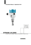
Dextens Electrochemical
Oxygen Sensors
Type 51100
Operating Manual
April 2012
Table of Content
1
GENERAL INFORMATION.........................................................................................................................................4
1.1
1.2
1.3
1.4
2
INDRODUCTION.........................................................................................................................................................5
2.1
2.2
2.3
3
CONTENT OF PACKAGE: OXYGEN SENSOR ..............................................................................................................5
ACCESSORIES .......................................................................................................................................................5
CONSUMABLES AND SPARE PARTS .........................................................................................................................7
INSTALLATION ..........................................................................................................................................................9
3.1
3.2
3.3
3.4
3.5
3.6
4
DISCLAIMER ..........................................................................................................................................................4
SYMBOLS AND CONVENTIONS ................................................................................................................................4
SERVICES AND REPAIRS ........................................................................................................................................4
CE CONFORMITY ..................................................................................................................................................4
INTRODUCTION ......................................................................................................................................................9
SENSOR DIMENSIONS ............................................................................................................................................9
FLOW CHAMBER INSTALLATION ............................................................................................................................10
SENSOR SOCKET INSTALLATION...........................................................................................................................11
INSERTION-EXTRACTION VALVE INSTALLATION .....................................................................................................11
KIT 82400 FOR SENSOR IN-LINE INSTALLATION .....................................................................................................12
MAINTENANCE ........................................................................................................................................................13
4.1
4.2
4.3
4.4
INTRODUCTION ....................................................................................................................................................13
WHEN TO CLEAN A SENSOR ?...............................................................................................................................13
MAINTENANCE TOOLS AND MATERIAL....................................................................................................................14
CLEANING THE SENSOR .......................................................................................................................................15
5
CALIBRATION..........................................................................................................................................................27
6
TESTING ...................................................................................................................................................................28
6.1
6.2
7
TROUBLE SHOOTING .............................................................................................................................................29
7.1
7.2
7.3
7.4
7.5
8
INTRODUCTION ....................................................................................................................................................28
SODIUM-SULFITE TEST .........................................................................................................................................28
CALIBRATION OUTSIDE OF THE DEFINED RANGE ....................................................................................................29
PUNCTURED MEMBRANE .....................................................................................................................................29
EMPTY ELECTROLYTE RESERVOIR .......................................................................................................................29
DIRTY SENSOR ...................................................................................................................................................29
SLOW SENSOR....................................................................................................................................................29
TECHNICAL SPECIFICATIONS ..............................................................................................................................30
Dextens SA 18 Chemin des Aulx 1218 Plan-les-Ouates Switzerland
T + 41 22 884 83 06 F + 41 22 342 48 60 [email protected] www.dextens.ch
3
1
General Information
1.1 Disclaimer
Please read and understand the user manual before installing and using the products described herein. It is also
recommended to follow the safety recommendations from this manual.
The material in this manual is for informational purposes only. The products it describes are subject to change without
prior notice, due to the manufacturer’s continuous development program.
Dextens makes no representations or warranties with respect to this manual and shall not be liable for any damages,
losses, costs or expenses, direct, indirect or incidental, consequential or special, arising out of, or related to the use of
this manual.
All rights reserved. No part of this manual may be used or reproduced in any form or by any means without prior written
permission of Dextens.
1.2 Symbols and Conventions
The danger sign (below) indicates actions or configurations that may be dangerous for the user or that may lead to
wrong measurements. Read and understand these paragraphs before starting to use the described material.
1.3 Services and Repairs
No sensor components can be repaired by the user. Only personnel from Dextens or its approved representative(s) is
(are) authorized to attempt repairs to the sensor and only components formally approved by the manufacturer should be
used.
Any attempt at repairing the sensor in contravention of these principles could cause damage to the sensor and corporal
injury to the person carrying out the repair. It renders the warranty null and void and could compromise the correct
working of the sensor and the electrical integrity or the CE compliance of the sensor.
1.4 CE Conformity
The TC sensors instruments are manufactured conforming to the requirements of the electromagnetic compatibility
directive 89/336/CEE and the low voltage directive 73/23/CEE.
Dextens SA 18 Chemin des Aulx 1218 Plan-les-Ouates Switzerland
T + 41 22 884 83 06 F + 41 22 342 48 60 [email protected] www.dextens.ch
4
2
Indroduction
2.1 Content of Package: oxygen sensor
When ordering a 51100 oxygen sensor, you will receive the following items:
5110 oxygen sensor with its calibration cap (1), collar (2)
and storage foot (3)
1
1
2
3
2
3
This user manual
2.2 Accessories
Depending on your order, additional accessories can be delivered:
Part Nr. 75502.mmm
Cable for connecting the sensor to a process or portable
instrument
Part Nr. 87410 / 87411
Sensor maintenancee kit
Dextens SA 18 Chemin des Aulx 1218 Plan-les-Ouates Switzerland
T + 41 22 884 83 06 F + 41 22 342 48 60 [email protected] www.dextens.ch
5
Introduction
Part Nr. 73100
Cleaning unit
Part Nr. 74001.00 / 74002.00
Tuchenhagen insertion device,
for Ø25mm or Ø28mm sensors.
Part Nr. 74010.00 / 74011.00
Tuchenhagen adapter,
for Ø25mm or Ø28mm sensors.
Part Nr. 74003.00 / 74004.00
Pipe adaptor for welding,
for Ø25mm or Ø28mm sensors.
Part Nr 74006.000 / 74006.001 / 74007.000 / 74007.001
Stainless steel flow chamber,
for Ø25mm or Ø28mm sensors
with 6mm or ¼’’ fittings.
Part Nr. 74009.000 PEEK
flow chamber, for Ø28mm sensor
with 6mm fittings.
Dextens SA 18 Chemin des Aulx 1218 Plan-les-Ouates Switzerland
T + 41 22 884 83 06 F + 41 22 342 48 60 [email protected] www.dextens.ch
6
Introduction
Part Nr. 71001
Storage foot
Part Nr. 71002
Calibration cap
Part Nr. 71003
Collar
2.3 Consumables and spare parts
Depending on your order, additional consumables and spare parts can be delivered:
Part Nr. 82000
Box of 5 rubber gaskets.
Part Nr. 82001
Box of 5 rubber gaskets with grill and gauze.
Part Nr. 82952
Box of 5 Tefzel 25µm membranes.
Dextens SA 18 Chemin des Aulx 1218 Plan-les-Ouates Switzerland
T + 41 22 884 83 06 F + 41 22 342 48 60 [email protected] www.dextens.ch
7
Introduction
Part Nr. 82956
Box of 5 PFA 25µm membranes.
Part Nr. 82059
Electrolyte bottle, 50ml.
Part Nr. 82132
Polishing powder 3µm.
Part Nr. 82134
Polishing cloth.
Dextens SA 18 Chemin des Aulx 1218 Plan-les-Ouates Switzerland
T + 41 22 884 83 06 F + 41 22 342 48 60 [email protected] www.dextens.ch
8
3
Installation
3.1 Introduction
The oxygen sensor can be mounted in a sample by means of a flow chamber, a sensor socket, or an insertion /
extraction valve. The following paragraphs describes how to uses these accessories. The sensor interfaces the
instrument via a 10-pin LEMO connector. The standard sensor cable length is three meters, but longer cable of up to
100 meters can be provided without any loss in signal sensitivity.
3.2 Sensor Dimensions
Dexens provides 2 types of sensor diameters depending of the application requirements. Look at the following sensor
drawings to get detailed dimensions. All accessories are made in 2 versions to be compatible with both sensor versions.
Sensor 51100: Ø 28mm
Sensor 51100: Ø 25mm
Dextens SA 18 Chemin des Aulx 1218 Plan-les-Ouates Switzerland
T + 41 22 884 83 06 F + 41 22 342 48 60 [email protected] www.dextens.ch
9
Installation
3.3 Flow Chamber Installation
The model 74006 or 74007 flow chambers are used to draw non-carbonated or stilled liquid or gaseous samples past
the sensor 61100 Ø 25mm and sensor 61101 Ø 28mm respectively. They connects to 6-mm or 1/4" stainless steel
tubing by means of two Swagelok fittings. Stainless steel or plastic tubing with very low permeability is used as
connecting tubing. The sample enters the chamber via the center inlet port located on the flow chamber and the outer
port is used as the sample out.
The flow chambers are designed to limit the sensor in contact with the sample to the membrane surface only. When
switching from a liquid sample to a span gas, make sure the front end of the sensor is clean and dry.
The flow chamber/sensor assembly should be
mounted either vertically or horizontally, under the
following conditions:
Sample
Flow Chamber Orientation
Gaseous or liquid
Vertically (sensor uppermost)
Gaseous, with
occasional liquid or
vapor
Horizontally, with outlet valve
under inlet, to
allow for drainage
If you require a calibration gas and normal sample media
to the flow chamber, use one 3-way valve on each port.
Calibration gas is sent in through the sample "out" port and
waste gas is sent out through the sample "in" port. Back in
normal operation (right), the calibration gas inlets and
outlets are shut off.
Dextens SA 18 Chemin des Aulx 1218 Plan-les-Ouates Switzerland
T + 41 22 884 83 06 F + 41 22 342 48 60 [email protected] www.dextens.ch
10
Installation
3.4 Sensor Socket Installation
The model 74003 / 74004 sensor sockets are for sensor 61100 Ø 25mm and sensor 61101 Ø 28mm respectively. The
sensor socket enables the sensor to be installed into any stainless steel pipe with a diameter greater than 50mm. The
sensor extends 28.5mm into the sensor socket. When cutting the sensor socket to fit the radius of your pipe, you should
allow for a 4mm setback between your pipe's inner diameter and the top of the sensor. This will prevent noisy readings
due to sample turbulences in front of the sensor.
Sensor socket mounting-side view
Be sure to remove the sensor socket's two O-rings prior to pipe welding and re-attach the sensor socket collar before
welding begins. This prevents distortion of metal threads during welding.
In-line analysis puts the sensor in direct contact with the bulk sample flow. This can be achieved in a number of ways.
The sensor can be positioned in a number of locations and sample conditions:
• Horizontally or with a small positive angle of 5 º
• On a horizontal stretch of pipe (or on flow-ascending vertical pipe)
• On the pump's discharge side and, if possible, at least 15 meters downstream
• Sensor should not be installed on the suction side of a pump,
• Sensor should not be installed close to valves or bends in the pipe.
• Sensor should not be installed near air or carbon dioxide injection if no static mixer or frit is used. The gas might not be
dissolved and it might give lower reading than expected or gas bubbles exploding on the membrane surface will
generate noisy readings.
3.5 Insertion-Extraction Valve Installation
A pipe adapter would require the whole system to be shut down before the sensor could be removed for service. For
maximum flexibility without interfering with the production run or process, a self sealing device such as Tuchenhagen
housing together with a specially made hygienic Dextens insertion device allows the sensor to be removed by simply
unscrewing the mounting collar which simultaneously closes the valve.
Dextens SA 18 Chemin des Aulx 1218 Plan-les-Ouates Switzerland
T + 41 22 884 83 06 F + 41 22 342 48 60 [email protected] www.dextens.ch
11
Installation
The model 74000 / 74001 insertion devices are for sensor 51100 Ø25mm and sensor 51101 Ø28mm respectively. It
allows a sensor to be inserted or removed from a pipe while the sample is still flowing. It clamps to the Tuchenhagen
Varivent in-line access unit which can be purchased directly from the manufacturer and is held into place by a stainless
steel clamp.
Sensor installed in an insertion device—cross section view
Location requirements are as stated above for the sensor socket. To insert the sensor, screw on the sensor collar until
coming to a stop, using the insertion device collar wrench provided. The sensor is securely tightened using the wrench
to screw up the insertion device collar. The wrench is fitted with two small pins and one of them is inserted into the
insertion device collar hole, the two ones being located 180 º apart.
Whilst screwing the insertion device collar, the valve will open up placing the sensor in-line. Removal is accomplished
by unscrewing the collar. When unscrewing the collar, the valve will close before the sensor can be removed, avoiding
any leakage of the sample.
This valve can withstand line pressures of up to 20 bar, with or without the sensor in place. The insertion device is
designed so that the O rings sealing the valve will be also exposed to the CIP chemicals, thus ensuring that hygiene is
maintained.
3.6 Kit 82400 for sensor in-line Installation
The in-line measurement of oxygen requires the sensor to withstand
harsh operating conditions in some applications. When there is a sudden
change in the line hydrostatic pressure, the membrane can inflate
resulting in erratic oxygen reading.
Dexens proposes a kit with parts to be inserted inside the hat-shaped
cap of the sensor. This kit contains a tefzel washer, a metallic grille, a
Dacron gauze and a silicone washer.
With such kit installed the sensor can withstand sudden and abrupt
pressure variation of ± 7 bars. Should you require to install such kit in
your sensor, you will need to dissemble the hat-shaped cap as explained
in section 3.3 and reassemble the sensor with the kit as explained in
section 3.7.
Dextens SA 18 Chemin des Aulx 1218 Plan-les-Ouates Switzerland
T + 41 22 884 83 06 F + 41 22 342 48 60 [email protected] www.dextens.ch
12
4
Maintenance
4.1 Introduction
The Dexens sensor has been designed to reduce the need of maintenance and to simplify this operation. The service
intervals can vary greatly from one-measurement conditions.
The purpose of this chapter is to describe in depth the way to clean the sensor and the tools that are used for this.
4.2 When to clean a sensor ?
There is no definitive rule to when you clean a sensor, nor is there a “standard” service interval. Cleaning frequency is
directly related to how much oxygen has passed onto the cathode.
However, you should clean a sensor when:
• It is slow
• It is noisy
• The calibration is out of range
• It is visibly dirty
4.2.1 Slow sensors
When sensors are becoming slower, they may need a maintenance. The test procedure for detecting slow sensors is
quite simple. Plunge the sensor without grid and gauze in water saturated with sodium sulfite. If the reading is below
10ppb after 10minutes, the sensor is fast enough.
Unfortunately this test is not always possible (for example, for in-line sensors). In such cases the operator must detect
sluggish responses by comparing the sensor’ speed over a chosen period of time.
4.2.2 Noisy sensors
First of all, the sensor noise is only visible at low oxygen concentration (50ppb and below). Above that limit, the sensor
noise is not significant. The test procedure is similar to the speed detection. Plunge the sensor in water saturated with
sodium sulfite. When the reading drops below 50ppb, and a reading variation of 10ppb is noticed, the sensor is noisy.
4.2.3 Verification of Cleanness of a Sensor
After cleaning the sensor, the operator may want to check if it is clean before remounting it. First of all make a visual
control:
• The anode color must be a light grey (look at pictures below).
• The cathode must be yellow (color of gold) without a white film.
• The guard must be grey (silver color).
In case the cathode or the guard are do not have the correct color, consider polishing the sensor. If the anode
is still dark, repeat electrochemical cleaning as long as there are no bubbles present in the electrolyte.
Anode before cleaning
Anode after cleaning
Dextens SA 18 Chemin des Aulx 1218 Plan-les-Ouates Switzerland
T + 41 22 884 83 06 F + 41 22 342 48 60 [email protected] www.dextens.ch
13
Maintenance
4.3 Maintenance tools and material
The maintenance kit (sold separately, look at the accessories in paragraph 1.2) provides the necessary tools for
cleaning the sensor and replacing the membrane. Take a look at the picture below for a detailed description of the
maintenance kit content.
Maintenance kit description:
1.
Polishing Cloth
2.
Polishing Powder
3.
Electrolyte Bottle
4.
Sensor Holder
5.
Membrane Box
6.
Syringe
7.
Removal Tool
8.
Cleanin Adapter
9.
Exhaust Tube
10. Wrench
In addition to the maintenance kit, you will sometimes need ammonia (concentration 30%) and
nitric acid (concentration 65%). When handling these product always wear protective gloves and
goggles.
Dextens SA 18 Chemin des Aulx 1218 Plan-les-Ouates Switzerland
T + 41 22 884 83 06 F + 41 22 342 48 60 [email protected] www.dextens.ch
14
Maintenance
4.4 Cleaning the Sensor
4.4.1 Dismantle the Sensor
First remove the sensor from the measurement point, please report to the related section in the paragraph 3. Then
follow the explanation hereunder to dismantle the sensor.
Description
Picture
When delivered, a new sensor assembly looks as
follows:
1. Disconnect the various protective and support
components by unscrewing them
1
2
3
2. Remove the locking screw with the removal tool
3. Remove the protective cap by pulling it off (this will
require some force)
If your sensor is fitted with a protective grid (inside the
protective cap), do not discard it as it is often reuseable. If there is no protective grid there will be a seal
– this is also often re-useable.
Dextens SA 18 Chemin des Aulx 1218 Plan-les-Ouates Switzerland
T + 41 22 884 83 06 F + 41 22 342 48 60 [email protected] www.dextens.ch
15
Maintenance
4. Place the sensor in the sensor holder. The small pin
in the holder must fit into the exhaust hole in the
reservoir.
Turn the sensor about 30 degrees clockwise to open the
reservoir (the hole and the mark must be aligned).
From this point, you must take particular care because
the electrolyte may leak from the reservoir.
Remark: it is possible to unscrew the reservoir without
this , but there are more risks to damage the membrane
5. Unscrew the electrolyte reservoir. Be careful with the
electrolyte - it is corrosive. Wear protective gear.
6. Unscrew the membrane lock
7. Remove the membrane frame. You can either use a
finger nail or the back side of a blade to lift the
membrane frame.
Dextens SA 18 Chemin des Aulx 1218 Plan-les-Ouates Switzerland
T + 41 22 884 83 06 F + 41 22 342 48 60 [email protected] www.dextens.ch
16
Maintenance
Upon disassembly the reservoir has the following
components:
4.4.2 Cleaning Methods
There are two cleaning methods:
•
Basic cleaning (electrochemical cleaning) – to be performed about every 6 – 12 months depending on the
application to ensure consistent readings from the sensor.
•
Aggressive cleaning (chemical cleaning) – this is an aggressive chemical cleaning. This cleaning only needs to be
performed in exceptional circumstances
4.4.3 Basic Cleaning
The electrochemical cleaning is done easily thanks to the Dextens cleaning station (sold separately, look at the
accessories paragraph 1.2). In most cases, it is enough to start an automatic cleaning cycle to refresh the sensor and
restore its initial performance, for more information about this operation, please refer to the cleaning station’s user
manual. The following s are given here only for informational purpose.
1. Connect the cleaning counter electrode to the sensor
2. Using a cable, connect the sensor to the cleaning
station
Remark: Orbisphere cleaning system can also be used
(with an adaptator)
Dextens SA 18 Chemin des Aulx 1218 Plan-les-Ouates Switzerland
T + 41 22 884 83 06 F + 41 22 342 48 60 [email protected] www.dextens.ch
17
Maintenance
3. Put the sensor on the sensor stand
4. Fill the counter electrode with electrolyte covering the
cathode
5. Start the electro-chemical cleaning on all electrodes.
6. Select the component for cleaning either individually:
Anode, Cathode, Guard
or:
All three
Press start/stop button to begin cleaning – the system
will stop automatically when cleaning is complete, the
lights will no longer flash.
7. Rinse the sensor abundantly with water (tap water is
fine), particularly the space between guard and cathode
Dextens SA 18 Chemin des Aulx 1218 Plan-les-Ouates Switzerland
T + 41 22 884 83 06 F + 41 22 342 48 60 [email protected] www.dextens.ch
18
Maintenance
Remark: A suggested vessel to provide the stream of
water looks like this
4.4.4 Aggressive Cleaning
Most often, you may skip the content of this section. But when the sensor is very dirty, for example after one year of
continuous work or after membrane breakage, it may be useful to clean the sensor with ammonia and acid. In such
case, follow the few next s
1. Screw the sensor storage foot on to the base of the
sensor and place the cleaning adapter in place of the
electrolyte reservoir.
2.Fill the cleaning adapter with ammonia (30%)
• Put a few of drops on the cathode so it is covered.
• Wait 3 minutes
Dextens SA 18 Chemin des Aulx 1218 Plan-les-Ouates Switzerland
T + 41 22 884 83 06 F + 41 22 342 48 60 [email protected] www.dextens.ch
19
Maintenance
3. Rinse the sensor abundantly
seconds (tap water is fine)
with water for 30
4. Fill the cleaning adapter with nitric acid (65%). Put a
few drops on the cathode so it is covered.
Wait 10 seconds - maximum
5. Rinse the sensor for 5 minutes with water (tap
water is fine). Inspect the guard which should be
uniformly white after the nitric acid cleaning. If it is not,
repeat the cleaning exercise.
Dextens SA 18 Chemin des Aulx 1218 Plan-les-Ouates Switzerland
T + 41 22 884 83 06 F + 41 22 342 48 60 [email protected] www.dextens.ch
20
Maintenance
6. Fill the cleaning adapter with ammonia (30%)
• Put a few drops on the cathode so it is covered.
• Wait 3 minutes
7. Rinse the sensor abundantly
with water for 1 minute
8. Put some polishing powder and distilled water on the
polishing cloth
9. Place the electrolyte reservoir (without membrane) on
the sensor.
Dextens SA 18 Chemin des Aulx 1218 Plan-les-Ouates Switzerland
T + 41 22 884 83 06 F + 41 22 342 48 60 [email protected] www.dextens.ch
21
Maintenance
10. Polish the sensor by making big circles until the
silver ring between the cathode and the guard is shiny.
The sensor must be held vertically.
Do not press the sensor on the polishing cloth. Only use
its own weight.
Avoid skin contact with the polishing cloth; it should be
kept free of dust and grease. After use rinse the
polishing cloth and dish with water and replace the lid to
keep dust off the cloth.
11. Remove the electrolyte reservoir and rinse the
reservoir thoroughly.
12. Remove the remaining polishing powder from the
sensor and the electrolyte reservoir using water.
The best results are obtained when the water is targeted
on the ring between the cathode and guard. The
cathode and guard should be shiny. If they are not, repolish as above.
Now inspect the cathode and guard with a magnifying
glass – ensure there are no polishing powder particles
on the surface and particularly, between the cathode
and guard.
Note: Following an aggressive cleaning we recommend
a basic cleaning.
13. Replace the electrolyte reservoir.
Dextens SA 18 Chemin des Aulx 1218 Plan-les-Ouates Switzerland
T + 41 22 884 83 06 F + 41 22 342 48 60 [email protected] www.dextens.ch
22
Maintenance
4.4.5
Reassemble the Sensor
This is one of the most important part of the cleaning procedure. If it is not done correctly, the sensor’s performances
will be affected and in some cases it will be necessary clean the sensor again. Therefore, read very carefully this
paragraph and understand the instructions.
1. Select the right membrane:
• Black : 82952 (in-line)
• Beige: 82956 (portable and package applications)
2. Clip the membrane frame on top of the reservoir.
Take care not to touch the membrane because it is very
fragile.
3. Clip the membrane frame on top of the reservoir.
Take care not to touch the membrane because it is very
fragile.
Remark: Make sure the reservoir is open (2 holes are
aligned as shown on picture)
4. Put about 5 drops of electrolyte on the membrane –
about 2-3 mm depth. Inspect the electrolyte through a
magnifying glass – there should be NO bubbles in the
electrolyte.
Dextens SA 18 Chemin des Aulx 1218 Plan-les-Ouates Switzerland
T + 41 22 884 83 06 F + 41 22 342 48 60 [email protected] www.dextens.ch
23
Maintenance
5. Carefully place 5 drops of electrolyte on the cathode
and a few drops at the bottom of the anode. It is
important to make sure that the space between the
cathode and guard is filled with electrolyte.
6. Carefully and slowly screw the sensor into the
reservoir – this should be done with the reservoir OPEN
(the two holes should be aligned – see section 3.3).
Carefully inspect the membrane, cathode and guard
area with a magnifying glass to make sur that there are
no air bubbles – particularly between the cathode and
guard.
Remark: make sure the electrolyte reservoir is OPENED
when you attach it to the sensor!
7. Place the sensor in the holder.
The hole on the electrolyte reservoir (A) fits on the
nipple of the holder (B).
Fix the sensor by slightly screwing in the handle - the
plunger should not touch the membrane yet.
A
B
The hole (C) is used for the filling syringe (see slide 37).
C
Remark 1:
The electrolyte reservoir is opened when the dots are
aligned.
Dextens SA 18 Chemin des Aulx 1218 Plan-les-Ouates Switzerland
T + 41 22 884 83 06 F + 41 22 342 48 60 [email protected] www.dextens.ch
24
Maintenance
Remark 2:
The reservoir is closed when the dots are not aligned.
8. Connect the exhaust tube. Place the open end in
your electrolyte container.
9. The syringe filled with electrolyte is connected to the
hole (C)
10. The fully prepared filling station looks like this.
Before filling, tighten the plunger so that it is touching
the membrane with a light pressure.
Fill the reservoir by slowly squeezing the syringe closed,
until electrolyte comes out of the exhaust tube. Shake
the end of the sensor and make sure that there are no
bubbles visible.
Dextens SA 18 Chemin des Aulx 1218 Plan-les-Ouates Switzerland
T + 41 22 884 83 06 F + 41 22 342 48 60 [email protected] www.dextens.ch
25
Maintenance
11. Now, unscrew the plunger enough, so that it is not
touching the membrane (to avoid damage to the
membrane).
Close the reservoir by turning the body of the sensor
from the open position (shown here) to the closed
position (the dots are not aligned).
12. Unscrew the support fully and remove the sensor
from the holder.
Shake the sensor and inspect the reservoir to make
sure there are no bubbles visible. If there are bubbles,
top up the reservoir to make sure that they disappear.
Inspect the cathode and guard with a magnifying glass
to make sure that there are no air bubbles beneath the
membrane.
13. Replace the grid or seal as appropriate.
14. Carefully replace the protective cap ensuring the
grid/seal remains properly centered.
15. Replace the locking screw with the removal tool
Dextens SA 18 Chemin des Aulx 1218 Plan-les-Ouates Switzerland
T + 41 22 884 83 06 F + 41 22 342 48 60 [email protected] www.dextens.ch
26
5
Calibration
After cleaning the sensor, it is mandatory to recalibrate the sensor on a Dexens 61100 instrument to ensure the
calibration parameters are correctly written in the sensor’s memory. Please report to the instrument manual for the
detailed calibration parameters and procedure.
• Connect the sensor to an instrument
• Start a calibration
• Let the calibration stabilize (1 hour)
• After 1 hour, efficiency should be in the range 80% to 120%
• If it is in this range, confirm the calibration. If not, see trouble-shooting at the end of this document
For a good calibration, be sure the sensor is completely mounted in its final setting and the Dacron gauze (if installed) is
dry. Not following these 2 rules is to get a bad calibration which will cause bad measurements.
The calibration is also a first way to check the sensor, even if the instruments accept efficiencies from 50% to 150%
having efficiencies from 90% to 110% is a sign of a good maintenance.
Dextens SA 18 Chemin des Aulx 1218 Plan-les-Ouates Switzerland
T + 41 22 884 83 06 F + 41 22 342 48 60 [email protected] www.dextens.ch
27
6
Testing
6.1
Introduction
• Connect the sensor to an instrument
• Check the speed and residual current of the sensor by performing a Sodium Sulfite test
• The sensor should read less than 10 ppb within 10 minutes and less than 0.4 ppb within 60 minutes. See troubleshooting if this performance is not achieved
6.2
Sodium-sulfite test
• Testing Dextens EC sensors performance and speed is done by connecting the sensor to an instrument (process,
portable or package analyzer) and plunging the sensor into a sodium sulfite solution. The sodium sulfite solution has
the effect of completely eliminating oxygen from the water.
• In order to complete this test, you need to create the sodium sulfite solution. Details of the sodium sulfite powder are
provided below.
• Select a glass or beaker (250 ml is sufficient) and add tap water to about 2/3 full. Add 2-3 teaspoons of the sodium
sulfite powder and stir for 20-30 seconds. The concentration is correct if a small amount of powder remains undissolved.
• Connect the sensor to an instrument and place it in the sodium sulfite solution. After 10 minutes in the sulfite, the
reading must be less than 10ppb and after 1hour, the reading should be lower than 1ppb.
• NOTE – if there is un-dissolved powder in the solution take care that it does not touch the membrane as this can
damage the membrane.
Dextens SA 18 Chemin des Aulx 1218 Plan-les-Ouates Switzerland
T + 41 22 884 83 06 F + 41 22 342 48 60 [email protected] www.dextens.ch
28
7
Trouble shooting
Even if Dexens sensors have been designed to reduce the sources of trouble, some harsh working condition may lead
to sensor malfunction. This chapter is here to give some tips to find and correct the problem.
7.1
Calibration outside of the defined range
• Calibration below 80% - it is possible that the reservoir is overfilled. Open and close the reservoir to reduce pressure
and re-measure efficiency.
• Calibration above 120% - membrane is probably too tight. Place in warm water overnight and re-measure efficiency.
7.2
Punctured Membrane
A common problem with our sensor is that the membrane is fragile and can be easily punctured or torn (when not
protected by the protective grill). The symptoms of this problem are reading that are not going down or very slowly. The
only response to this is to thoroughly clean the sensor and replace the membrane. When the membrane has been
broken the sampling liquid enters the reservoir. To get a fully working sensor you will remove all traces of the liquid.
7.3
Empty Electrolyte Reservoir
Another frequent problem is that the electrolyte leaks out of the reservoir. This happens after bad maintenance when
the operator has not completely closed the reservoir. But the effect of this problem can sometimes be detected after a
quite long time because of a small leak. The symptoms of this problem are a sensor that is not measuring anything and
which becomes very sensitive to pressure changes. To correct the problem, do a complete maintenance taking much
care to completely close the electrolyte reservoir.
7.4
Dirty Sensor
After some time, in normal use, the sensors becomes dirty. They are much slower to go down and the response signal
is quite noisy. The only thing to do is a maintenance, some times with a chemical clean (see §4.4.4).
7.5
Slow Sensor
If, when completing the sodium sulfite test, the sensor does not reach 10 ppb in 10 minutes AND 0.4 ppb in 60 minutes
then let the sensor sit for 1 hour connected to the instrument. This will allow the sensor to consume any oxygen which
may reside in the electrolyte.
• Inspect the sensor for air bubbles. If there are none, then, retest the sensor speed. If there are bubbles you must
rework the reservoir to remove them – either by topping-up the reservoir or completely refilling it. (Note – if you
completely refill the reservoir you should recalibrate the sensor).
• If the sensor is still not delivering to specification (bullet point 1 above) allow it to sit overnight connected to the
instrument and retest.
• If after testing and allowing the sensor to sit either for an hour or overnight performance is still not to specification
check the following:
• Is the membrane clean?
• Are there no bubbles in the reservoir?
• Inspect the cathode, guard and anode – are they clean? Even if they appear clean, re-clean the sensor (we
recommend both aggressive and basic cleaning) and recalibrate and retest.
• If after cleaning, re-cleaning and retesting the sensor is still not performing well, we recommend you contact Dextens
Dextens SA 18 Chemin des Aulx 1218 Plan-les-Ouates Switzerland
T + 41 22 884 83 06 F + 41 22 342 48 60 [email protected] www.dextens.ch
29
8
Technical Specifications
Membrane
Utilization of various membranes according to measuring range
Membrane model number
82956
82952
82935
Measuring range DO2
0.1ppb – 20ppm
1ppb – 100ppm
10ppb – 400ppm
Measuring range PO2
0 - 4 bars
0 – 2 bars
0 – 10 bars
Liquid flow rate
180 ml/min
50 ml/min
25 ml/min
Linear flow
200 cm/sec
30 cm/sec
20 cm/sec
Gaseous flow rate
0.005 – 3 l/min
0.005 – 3 l/min
0.005 – 3 l/min
Response time (90%
at 25°C)
7.2 sec
38 sec
2.5 min
Accuracy
Temperature compensation
1% of the measured value or lowest value whichever is greater
Absolute zero and low drift
-5°C to + 60°C / 23°F to 140°F
Temperature range
CIP or SIP resistant up to 120°C / 248°F
Pressure rating
300 bars or 4350 Psi
Weight
0.6 kg
Enclosure protection
IP68/NEMA6P
Material in contact
with sample
Stainless steel (ANSI 316L), PFA or Tefzel
Sensor model number
Model 51102: Ø25mm - Model 51101: Ø28mm
Sensor cable
3m standard length / optional extension up to 1000 m
Expected Oxygen Sensor Current
Membrane
Expected
current, in air at
25°C
Expected
current, in pure
oxygen
Minimum
expected current,
in pure oxygen
Maximum
expected
current, in pure
oxygen
O2 consumption in O2
saturated water at 25°C
82952A
5.4 µA
27 µA
8.1 µA
45.9 µA
37.38 µg/hour
82956A
82958A
26.4 µA
9.4 µA
132 µA
47 µA
39.6 µA
14.1 µA
224.4 µA
79.9 µA
1.193 µg/hour
3.59 µg/hour
Standard Sensor Cable Specifications
Casing
Fire-retardant Elastolan
Maximum temperature
80 °C
Cable diameter
6.1 mm ±0.3 mm. 10 each stranded wires of 26 AWG, individually insulated with
polyethylene, 90% shielded by tinned copper braid.
Maximum pulling tension
7 kg
Resistivity
138 Ω/km
Minimum bend radius
15 times cable diameter
Dextens SA 18 Chemin des Aulx 1218 Plan-les-Ouates Switzerland
T + 41 22 884 83 06 F + 41 22 342 48 60 [email protected] www.dextens.ch
30