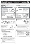
1
Introduction Congratulations! Having purchased a Car Mate Trailer affords the peace of mind that a wise consumer decision has been made. Car Mate’s commitment to quality, craftsmanship and customer service allows us to stake our claim as an industry leader. Car Mate meets or exceeds all standards of construction established by the National Association of Trailer Manufacturers (NATM). Being attentive to consumer needs and industry changes, Car Mate is a leader by offering a product line that boasts quality and features that are second to none. The following “Owner Guidelines” are just that – guidelines. A combination of cautions, suggestions, recommendations, facts and figures to make a first time owner’s experience a positive one and offer a refresher course for the veteran. By reading and understanding these guidelines, everyone that now owns a Car Mate Trailer should have years of safe, worry free “trailering”. Everyone at Car Mate Trailers is dedicated to offering the finest quality trailer on the market today. With thirty plus years of manufacturing experience combined with a sales and support staff focused on the needs of customers and dealers alike, Car Mate has that competitive edge needed to be a leader in today’s trailer manufacturing industry. Enjoy your new Car Mate Trailer! Visit us on the World Wide Web! –––– @ –––– www.carmate-trailers.com REV. 09/09 1 Table of Contents Introduction .......................................... 1 Trailer Data .......................................... 3 Reporting Safety Defects ...................... 3 Checklist .............................................. 4 Registration ........................................... 5 Gross Vehicle Weight Rating .................. 5 Tips for Carefree “Trailering” ................ 6 Trailer Hitch ......................................... 7 Safety Chains ....................................... 8 Couplers .............................................. 9 Lights ................................................... 9 Wheels and Hubs ................................. 10 Tire Safety ............................................ 10 Brakes ................................................. 23 “Getting Connected” ............................ 24 Weight Distribution ............................... 25 Trailer Jacks ......................................... 26 Tips ..................................................... 26 Storage ................................................ 26 Diagrams ............................................. 27 Break Away System 7 Pole Flat Pin Connector 4-Way Flat Connector Trailer Service History .......................... 28 Periodic Scheduled Maintenance Tips ... 28 2 Trailer Data Date of Purchase _____________________________________________ Model/Size ________________________ /________________________ Serial Number _______________________________________________ GVWR _____________________________________________________ Wheel/Tire Size _____________________ /_______________________ Color _____________________________________________________ Optional Equipment ___________________________________________ ___________________________________________ ___________________________________________ Reporting Safety Defects If you believe that your vehicle has a defect which could cause a crash or could cause injury or death, you should immediately inform the National Highway Traffic Safety Administration (NHTSA) in addition to notifying Car Mate Trailers. If NHTSA receives similar complaints, it may open an investigation, and if it finds that a safety defect exists in a group of vehicles, it may order a recall and remedy campaign. However, NHTSA cannot become involved in individual problems between you, your dealer, or Car Mate Trailers. To contact NHTSA, you may either call the Vehicle Safety Hotline toll-free at 1-888-327-4236 (TTY: 1-800-424-9153), go to http://www.safecar.gov; or write to: Administrator NHTSA 1200 New Jersey Avenue S.E. Washington, DC 20590 You can also obtain other information about motor vehicle safety from http://www.safercar.gov. 3 Checklist Read and understand the following instructions and warnings. Always check before towing a trailer: Coupler, hitch and hitch-ball are properly sized. Coupler and safety chains are safely secured to hitch. Check all fasteners and connections. Tie-downs are being used properly to secure cargo. Wheel lug nuts are properly torqued. (Please refer to “Torque Chart” inside back cover) Wheel bearings are properly adjusted and maintained. Load is within maximum load carrying capacity. Tires are properly inflated. All trailer lighting is working properly. Trailer brakes & brake controller are properly adjusted and working. (If applicable) Trailer is equipped to meet all federal DOT safety standards. Check state and local requirements regarding brakes. Trailer wheels should be chocked and secured when loading. When loading a single axle trailer not connected to a tow vehicle, tipping may occur. Stabilizing the rear of the trailer is recommended (use jacks, blocking, etc.). Warning: Never carry passengers inside trailer! 4 Registration: Warranty and Ownership Car Mate Trailers Limited Warranty applies to first purchasers only. Warranty cards should be completed at the time of purchase or signed and returned by the 15th day after purchase to validate warranty. Warranty registration also makes it possible for the manufacturer to notify first purchasers in the unlikely event of a defect notification. A Manufacturers Certificate of Origin (MCO) is issued at the time of purchase. This document is verification of ownership. State laws vary regarding the registering of trailers. Contact your state Department of Motor Vehicles to verify proper procedures. *Please Note: Trailer laws covering such things as brakes, lights, safety chains, licenses, etc. also vary from state to state. Be sure trailer is in full compliance with specific state laws. Contact your state Department of Motor Vehicles for complete information. Gross Vehicle Weight Rating (GVWR) Warning: The total weight of all cargo and trailer must not exceed the trailer’s maximum load capacity. Note: Maximum load carrying capacity is the gross vehicle weight rating (GVWR) less the weight of the empty trailer. The key to carefree “trailering” is the proper match of tow vehicle, trailer and cargo. Load Carrying Capacity Check the certification label attached by the manufacturer to the left forward side of trailer. It is required to show the Gross Vehicle Weight Rating (GVWR) which is the maximum towing capacity (trailer weight plus cargo weight). Be sure that the total weight of trailer and cargo does not exceed the GVWR. If the correct weight of tow vehicle, trailer and cargo is unknown, don’t guess – weigh it! This can be done at a local lumberyard, feed mill, truck stop, etc. Be careful not to overload trailer. If overloading occurs regularly, go to the next heavier rated trailer. When towing a trailer, the vehicle combination is longer, heavier, sometimes wider and taller than the tow vehicle. Exercise extreme caution to allow for these differences. 5 Tips for Carefree “Trailering” Take a “Shakedown Cruise” Before taking the first trip, make at least one short trial run to become familiar with different handling characteristics and be sure everything is working properly – lights, brakes, hitch, etc. Slow Down There is less strain on car and trailer at moderate to slow speeds. Many states have lower speed limits for vehicles towing trailers. Allow Extra Time and Space More of both are needed when passing and stopping, especially if trailer is not equipped with brakes. Check Rear View Mirrors It is recommended to install outside rear view mirrors on both sides of the tow vehicle. Check mirrors frequently to be sure trailer is towing properly. Swing Wider Trailer wheels are closer to the inside of turns than the wheels of the tow vehicle. Be sure to swing wider at curves and corners. Pass with Extra Care When towing a trailer, more time and distance is needed to safely pass slower moving vehicles. Watch the Wind Be prepared for sudden changes in air pressure and/or wind buffeting when larger vehicles pass from either direction. Slow down and keep a firm grip on the steering wheel. Conserve Fuel Wind resistance can reduce gas mileage significantly, especially at high speeds. Avoid Sudden Stops and Starts Even if a trailer has brakes, a sudden stop may cause it to skid, slide or even jackknife. Be especially careful to avoid quick stops while turning. Smooth, gradual starts and stops will improve gas mileage and reduce strain on tie downs, etc. Signal Your Intentions Before stopping, turning, changing lanes or passing, use light signals to alert other vehicles. 6 Shift to Lower Gear If tow vehicle has a manual transmission, using lower gears when going up steep hills or over sand, gravel or dirt roads will ease the load on your engine and transmission. If tow vehicle has an “overdrive” gear (manual or automatic) better gas mileage may be achieved in a lower gear. Always be Courteous Make it as easy as possible for faster-moving vehicles to pass. Keep to the right side of the road and be prepared to slow down if another vehicle needs extra time to pass. Don’t Tailgate Allow at least one car and trailer length per 10 mph when following another vehicle. If a problem occurs “stay cool”, don’t panic. One such problem may be a flat tire. A sudden bumping or “fishtailing” may occur. Don’t jam on the brakes or over accelerate to try and “drive out of it”. Stop slowly, in as straight a line as possible. If conditions permit, coast to a very slow speed and try to avoid braking. Trailer Hitch Warning: The total weight of a loaded trailer must not exceed the capacity of the tow vehicle hitch. There are two basic types of trailer hitches: a weight-carrying hitch and a weight-distributing hitch. When towing lighter trailers with a passenger car, a weight-carrying hitch is adequate. A weight-distributing hitch may be recommended for heavier trailers. Before deciding which type of hitch to use, consult the vehicle manufacturers recommendation. Be sure the total weight of a loaded trailer does not exceed the hitch’s load capacity. The maximum allowable weight is stamped on the hitch. Also, be sure the hitch ball is sized to match the coupler. The correct ball diameter is marked on the trailer coupler. The hitch should also provide a place for attaching the trailer’s safety chains; (two rings or holes on either side of the hitch ball). A truck or van using a “step bumper” as the hitch platform will need chain attachments such as eye bolts along with a hitch ball installed according to the Society of the Automotive Engineers SAE J684 Standard. Installing a light or heavy-duty hitch can be a major undertaking. The hitch and its installation 7 should meet the SAE J684 Standard. It is recommended that the job be done by a professional dealer. Note: The trailer should be in a level position when hitched to the tow vehicle. Safety Chains Warning: Failure to properly attach safety chains between trailer and tow vehicle can result in a run-away trailer. Safety chains on a trailer provide added insurance that it will not become detached from the towing vehicle. Be certain that safety chains are correctly attached between the tow vehicle and the trailer before each use. As noted, the trailer hitch should provide a place for attaching safety chains, (holes or rings on both sides of the hitch ball). It is strongly recommended (required by most states) that safety chains crisscross under the trailer tongue, the chain on the left side of the trailer attached to the hole or ring on the right side of the hitch ball, the right side chain attached to the hole or ring on the left side of the hitch ball. This will prevent the trailer tongue from dropping to the road if the trailer coupler separates from the hitch ball. The chains should be rigged as tight as possible with just enough slack to permit tight turns. If replacement of a safety chain becomes necessary, do not substitute a lighter weight chain. The Society of Automotive Engineers standard for safety chains: Trailer Class 8 Trailer Weight Minimum Breaking Weight Class I to 2000 lbs. GVWR 2000 lbs. Class II 2000 to 3500 lbs. GVWR 3500 lbs. Class III 3500 to 5000 lbs. GVWR 5000 lbs. Class IV 5000 to 10000 lbs. GVWR The GVWR of the trailer Couplers Warning: Failure to engage the hitch ball in the coupler ball socket and securely lock the coupler latch may cause the trailer to become detached from the tow vehicle while in use. The trailer coupler is designed for maximum strength when the hitch ball is in its socket. It is necessary to exercise caution when the trailer is disconnected, not to damage the coupler in any way. The coupling socket should not be allowed to rest on the ground where dirt and sand can enter the socket. This will cause excessive wear when the trailer is next connected or cause the locking mechanism to jam. If the coupler becomes damaged it must be repaired or replaced immediately. When the coupler is placed on the ball, the latch should close firmly and a locking pin placed through the coupler. Keep the latch mechanism lightly oiled and cleaned. Warning: Always replace damaged couplers or latch assemblies before attempting to connect tow vehicle and trailer. Lights Warning: Check all trailer and tow vehicle lighting before each use. State and Federal regulations require all types of trailers be equipped with turn signals, tail, stop, and side marker lights. Trailers 80 inches and wider also require clearance and identification lights. The manufacturer supplies these lights. It is the owner’s responsibility to maintain lights in good working condition at all times. A special wiring harness for connecting trailer lights to the lighting system of the tow vehicle comes with the trailer. Be sure the white ground wire from the connector is attached to the frame so that the hitch ball does not act as an electrical connection. Hints to keep trailer lighting system in good working order: • At least once or twice a year, trace the wiring system from the tow vehicle to the trailer and back. Look for bare wires, cracked or chafed insulation and corroded or rusted terminals. Be sure the white ground wire is still connected to the trailer frame. Replace any parts that are damaged or badly worn. 9 • A small amount of waterproof grease on plug contacts and light bulb bases will help to prevent rust and corrosion. • Before every use, check for burned out or broken bulbs, cracked or broken light lenses, etc. Note: Basic wiring diagrams are available on page 15. Wheels and Hubs Warning: Maintain proper torque on wheel lug nuts. Please refer to “Torque Chart” inside back cover. Lug Nuts Loose lug nuts can cause more than just annoying “wheel wobble”, wheel loss may occur. Before each use, check for loose or missing lug nuts. Replace missing lug nuts immediately. Be certain a replacement lug nut is an exact match for the original. Lubrication Unless trailer is equipped with water-protected hubs, avoid submerging axles and hubs in water. When traveling, regularly check wheel hubs. If hubs feel abnormally hot, bearings should be inspected before continuing. Warning: Failing to properly lubricate wheel bearings may lead to bearing failure. Tire Safety This portion of the User’s Manual contains tire safety information as required by 49 CFR 575.6 Section 1.1 contains “Steps for Determining Correct Load Limit - Trailer”. Section 1.2 contains “Steps for Determining Correct Load Limit - Tow Vehicle”. Section 1.3 contains a Glossary of Tire Terminology, including “cold inflation pressure”, “maximum inflation pressure”, “recommended inflation pressure”, and other non-technical terms. 10 Section 1.4 contains information from the NHTSA brochure entitled “Tire SafetyEverything Rides On It”. This brochure as well as the preceding subsections, describes the following items: • Tire labeling, including a description and explanation of each marking on the tires, and information about the DOT Tire Identification Number (TIN). • Recommended tire inflation pressure, including a description and explanation of: A. Cold inflation pressure. B. Vehicle Placard and location on the vehicle. C. Adverse safety consequences of under inflation (including tire failure). D. Measuring and adjusting air pressure for proper inflation. • Tire Care, including maintenance and safety practices. • Vehicle load limits, including a description and explanation of the following items: A. Locating and understanding the load limit information, total load capacity, and cargo capacity. B. Calculating total and cargo capacities with varying seating configurations including quantitative examples showing/illustrating how the vehicles cargo and luggage capacity decreases as combined number and size of occupants’ increases. This item is also discussed in Section 3. C. Determining compatibility of tire and vehicle load capabilities. D. Adverse safety consequences of overlooking on handling and stopping on tires. 1.1 Steps for Determining Correct Load Limit–Trailer Determining the load limit of a trailer includes more than understanding the load limits of the tires alone. On all trailers there is a Federal certification/VIN label that is located on the forward half of the left (road) side of the unit. This certification/VIN label will indicate the trailer’s Gross Vehicle Weight Rating (GVWR). This is the most weight the fully loaded trailer can weigh. It will also provide the Gross Axle Weight Rating (GAWR). This is the most a particular axle can weigh. If there are multiple axles, the GAWR of each axle will be provided. If your trailer has a GVWR of 10,000 pounds or less, there is a vehicle placard located in the same location as the certification label described above. This placard provides tire and loading information. In addition, this placard will show a statement regarding maximum cargo capacity. Cargo can be added to the trailer up to the maximum weight specified on the placard. The combined weight of the cargo is provided as a single number. In any case, remember: the total weight of a fully loaded trailer can not exceed the stated GVWR. 11 For trailers with living quarters installed, the weight of water and propane also need to be considered. The weight of fully filled propane containers is considered part of the weight of the trailer before it is loaded with cargo, and is not considered part of the disposable cargo load. Water however, is a disposable cargo weight and is treated as such. If there is a fresh water storage tank of 100 gallons, this tank when filled would weigh about 800 pounds. If more cargo is being transported, water can be off-loaded to keep the total amount of cargo added to the vehicle within the limits of the GVWR so as not to overload the vehicle. Understanding this flexibility will allow you, the owner to make choices that fit your travel needs. When loading your cargo, be sure it is distributed evenly to prevent overloading front to back and side to side. Heavy items should be placed low and as close to the axle positions as reasonable. Too many items on one side may overload a tire. The best way to know the actual weight of the vehicle is to weigh it at a public scale. Talk to your dealer to discuss the weighing methods needed to capture the various weights related to the trailer. This would include the weight empty or unloaded, weights per axle, wheel, hitch or king-pin and total weight. Excessive loads and/or underinflation cause tire overloading and as a result, abnormal tire flexing occurs. This situation can generate an excessive amount of heat within the tire. Excessive heat may lead to tire failure. It is the air pressure that enables a tire to support the load, so proper inflation is critical. The proper air pressure may be found on the certification/VIN label and/or on the Tire Placard. This value should never exceed the maximum cold inflation pressure stamped on the tire. 1.1.1 Trailers 10,000 Pounds GVWR or Less 1. Locate the statement, “The weight of cargo should never exceed XXX kg or XXX lbs.,” on your vehicles’s placard. See figure 1-1. 2. This figure equals the available amount of cargo and luggage load capacity. 3. Determine the combined weight of luggage and cargo being loaded on the vehicle. That weight may not safely exceed the available cargo and luggage load capacity. 12 The trailer’s placard refers to the Tire Information Placard attached adjacent to or near the trailer’s VIN (Certification) label at the left front of the trailer. 1.1.2 Trailers over 10,000 pounds GVWR (Note: These trailers are not required to have a tire information placard on the vehicle.) 1. Determine the empty weight of your trailer by weighing the trailer using a public scale or other means. This step does not have to be repeated. 2. Locate the GVWR (Gross Vehicle Weight Rating) of the trailer on your trailer’s VIN (Certification) label. 3. Subtract the empty weight of your trailer from the GVWR stated on the VIN label. That weight is the maximum available cargo capacity of the trailer and may not be safely exceeded. 1.2 Steps For Determining Correct Load Limit–Tow Vehicle 1. Locate the statement, “The combined weight of occupants and cargo should never exceed XXX lbs.,” on your vehicle’s placard. 2. Determine the combined weight of the driver and passengers who will be riding in your vehicle. 3. Subtract the combined weight of the drive and passengers who will be riding in your vehicle. 4. The resulting figure equals the available amount of cargo and luggage capacity. For example, if the “XXX” amount equals 1400 lbs. and there will be five 150 lb. passengers in your vehicle, the amount of available cargo and luggage capacity is 650 lbs. (1400-750 (5x150) = 650 lbs.). 5. Determine the combined weight of luggage and cargo being loaded on the vehicle. That weight may not safely exceed the available cargo and luggage capacity calculated in Step #4. 6. If your vehicle will be towing a trailer, load from your trailer will be transferred to your vehicle. Consult the tow vehicle’s manual to determine how this weight transfer reduces the available cargo and luggage capacity of your vehicle. 1.3 Glossary of Tire Terminology Accessory Weight - The combined weight (in excess of those standard items which may be replaced) of automatic transmission, power steering, power brakes, power windows, power seats, radio and heater, to the extent that these items are available as factoryinstalled equipment (whether installed or not). Bead - The part of the tire that is made of steel wires, wrapped or reinforced by ply cords and that is shaped to fit the rim. Bead separation - This is the breakdown of the bond between components in the bead. 13 Bias ply tire - A pneumatic tire in which the ply cords that extend to the beads are laid at alternate angles substantially less than 90 degrees to the centerline of the tread. Carcass - The tire structure, except tread and sidewall rubber which, when inflated, bears the load. Chunking - The breaking away of pieces of the tread and sidewall. Cold inflation pressure - The pressure in the tire before you drive. Cord - The strands forming the piles in the tire. Cord separation - The parting of cords from adjacent rubber compounds. Cracking - Any parting within the tread, sidewall, or inner liner of the tire extending to cord material. CT - A pneumatic tire with an inverted flange tire and rim system in which the rim is designed with rim flanges pointed radially inward and the tire is designed to fit on the underside of the rim in a manner that encloses the rim flanges inside the air cavity of the tire. Curb weight - The weight of a motor vehicle with standard equipment including the maximum capacity of fuel, oil and coolant, and, if so equipped, air conditioning and additional weight optional engine. Extra load tire - A tire designed to operate at higher loads and at higher inflation pressures than the corresponding standard tire. Groove - The space between two adjacent tread ribs. Gross Axle Weight Rating - The maximum weight that any axle can support, as published on the Certification/VIN label on the front left side of the trailer. Actual weight determined by weighing each axle on a public scale, with the trailer attached to the towing vehicle. Gross Vehicle Weight Rating - The maximum weight of the fully loaded trailer, as published on the Certification/VIN label. Actual weight determined by weighing trailer on a public scale, without being attached to the towing vehicle. Hitch Weight - The downward force exerted on the hitch ball by the trailer coupler. Innerliner - The layer(s) forming the inside surface of a tubeless tire that contains the inflating medium within the tire. Innerliner separation - The parting of the innerliner from cord material in the carcass. Intended outboard sidewall - The sidewall that contains a white-wall, bears white lettering or bears manufacturer, brand, and/or model name molding that is higher or deeper than the same molding on the other sidewall of the tire or the outward facing sidewall of an asymmetrical tire that has a particular side that must always face outward when mounted on a vehicle. 14 Light truck (LT) tire - A tire designated by its manufacturer as primarily intended for use on lightweight trucks or multipurpose passenger vehicles. Load rating - The maximum load that a tire is rated to carry for a given inflation pressure. Maximum load rating - The load rating for a tire at the maximum permissible inflation pressure for that tire. Maximum permissible inflation pressure - The maximum cold inflation pressure to which a tire may be inflated. Maximum loaded vehicle weight - The sum of curb weight, accessory weight, vehicle capacity weight, and production options weight. Measuring rim - The rim on which a tire is fitted for physical dimension requirements. Pin weight - The downward force applied to the 5th wheel or gooseneck ball, by the trailer kingpin or gooseneck coupler. Non-pneumatic rim - A mechanical device which, when a non-pneumatic tire assembly incorporates a wheel, supports the tire, and attaches, either integrally or separately, to the wheel center member and upon which the tire is attached. Non-pneumatic spare tire assembly - A non-pneumatic tire assembly intended for temporary use in place of one of the pneumatic tires and rims that are fitted to a passenger car in compliance with the requirements of this standard. Non-pneumatic tire - A mechanical device which transmits, either directly or through a wheel or wheel center member, the vertical load and tractive forces from the roadway to the vehicle, generates the tractive forces that provide the directional control of the vehicle and does not rely on the containment of any gas or fluid for providing those functions. Non-pneumatic tire assembly - A non-pneumatic tire, alone or in combination with a wheel or wheel center member, which can be mounted on a vehicle. Normal occupant weight - This means 68 kilograms (150lbs.) times the number of occupants specified in the second column of Table 1 of 49 CFR 571.110. Occupant distribution - The distribution of occupants in a vehicle as specified in the third column of Table 1 of 49 CFR 571.110. Open splice - Any parting at any junction of tread, sidewall, or innerliner that extends to cord material. Outer diameter - The overall diameter of an inflated new tire. Overall width - The linear distance between the exteriors of the sidewalls of an inflated tire, including elevations due to labeling, decorations, or protective bands or ribs. 15 Ply - A layer of rubber-coated parallel cords. Ply separation - A parting of rubber compound between adjacent plies. Pneumatic tire - A mechanical device made of rubber, chemicals, fabric and steel or other materials, that, when mounted on an automotive wheel, provides the traction and contains the gas or fluid that sustains the load. Production options weight - The combined weight of those installed regular production options weighing over 2.3 kilograms (5 lbs.) in excess of those standard items which they replace, not previously considered in curb weight or accessory weight, including heavy duty brakes, ride levelers, roof rack, heavy duty battery, and special trim. Radial ply tire - A pneumatic tire in which the ply cords that extend to the beads are laid at substantially 90 degrees to the centerline of the tread. Recommended inflation pressure - This is the inflation pressure provided by the vehicle manufacturer on the Tire information label and on the Certification/VIN tag. Reinforced tire - A tire designed to operate at higher loads and at higher inflation pressures than the corresponding standard tire. Rim - A metal support for a tire or a tire and tube assembly upon which the tire beads are seated. Rim diameter - This means the nominal diameter of the bead seat. Rim size designation - This means the rim diameter and width. Rim type designation - This means the industry of manufacturer’s designation for a rim by style or code. Rim width - This means the nominal distance between rim flanges. Section width - The linear distance between the exteriors of the sidewalls of an inflated tire, excluding elevations due to labeling, decoration or protective bands. Sidewall - That portion of a tire between the tread and bead. Sidewall separation - The parting of the rubber compound from the cord material in the sidewall. Special trailer (ST) tire - The “ST” is an indication the tire is for trailer use only. Test rim - The rim on which a tire is fitted for testing, and may be any rim listed as appropriate for use with that tire. Tread - That portion of a tire that comes into contact with the road. Tread rib - A tread section running circumferentially around a tire. Tread separation - Pulling away of the tread from the tire carcass. 16 Treadwear indicators (TW) - The projections within the principal grooves designed to give a visual indication of the degrees of wear of the tread. Vehicle capacity weight - The rated cargo and luggage load plus 68 kilograms (150 lbs.) times the vehicle’s designated seating capacity. Vehicle maximum load on the tire - The load on an individual tire that is determined by distributing to each axle its share of the maximum loaded vehicle weight and dividing by two. Vehicle normal load on the tire - The load on an individual tire that is determined by distributing to each axle its share of the curb weight, accessory weight, and normal occupant weight (distributed in accordance with Table 1 of CRF 49 571.110) and dividing by 2. Weather side - The surface area of the rim not covered by the inflated tire. Wheel center member - In the case of a non-pneumatic tire assembly incorporating a wheel, a mechanical device which attaches, either integrally or separately, to the nonpneumatic rim and provides the connection between the non-pneumatic rim and the vehicle; or, in the case of a non-pneumatic tire assembly not incorporating a wheel, a mechanical device which attaches, either integrally or separately to the non-pneumatic tire and provides the connection between tire and the vehicle. Wheel-holding fixture - The fixture used to hold the wheel and tire assembly securely during testing. 1.4 Tire Safety - Everything Rides On It The National Traffic Safety Administration (NHTSA) has published a brochure (DOT HS 809 361) that discusses all aspects of Tire Safety, as required by CFR 575.6. This brochure is reproduced in part below. It can be obtained and downloaded from NHTSA, free of charge, from the following web site: http://www.nhtsa.dot.gov/cars/rules/TireSafety/ridesonit/tires_index.html Studies of tire safety show that maintaining proper tire pressure, observing tire and vehicle load limits (not carrying more weight in your vehicle than your tires or vehicle can safely handle), avoiding road hazards, and inspecting tires for cuts, slashes, and other irregularities are the most important things you can do to avoid tire failure, such as tread separation or blowout and flat tires. These actions, along with other care and maintenance activities, can also: • • • • Improve vehicle handling Help protect you and others from avoidable breakdowns and accidents Improve fuel economy Increase the life of your tires 17 This booklet presents a comprehensive overview of tire safety, including information on the following topics: • Basic tire maintenance • Uniform Tire Quality Grading System • Fundamental characteristics of tires • Tire safety tips Use this information to make tire safety a regular part of your vehicle maintenance routine. Recognize that the time you spend is minimal compared with the inconvenience and safety consequences of a flat tire or other tire failure. 1.5 Safety First–Basic Tire Maintenance Properly maintained tires improve the steering, stopping, traction, and load-carrying capability of your vehicle. Underinflated tires and overloaded vehicles are a major cause of tire failure. Therefore, as mentioned above, to avoid flat tires and other types of tire failure, you should maintain proper tire pressure, observe tire and vehicle load limits, avoid road hazards, and regularly inspect your tires. 1.5.1 Finding your vehicle’s recommended tire pressure and load limits Tire information placards and vehicle certification labels contain information on tires and load limits. These labels indicate the vehicle manufacturer’s information including: • Recommended tire size • Recommended tire inflation pressure • Vehicle capacity weight (VCW-the maximum occupant and cargo weight a vehicle is designed to carry) • Front and rear gross axle weight ratings (GAWR-the maximum weight the axle systems are designed to carry) Both placards and certification labels are permanently attached to the trailer near the left front. 1.5.2 Understanding tire pressure and load limits Tire inflation pressure is the level of air in the tire that provides it with loadcarrying capacity and affects the overall performance of the vehicle. The tire inflation pressure is a number that indicates the amount of air pressure–measured in pounds per square inch (psi)–a tire requires to be properly inflated. (You will also find this number on the vehicle information placard expressed in kilopascals (kpa), which is the metric measure used internationally.) Manufacturers of passenger vehicles and light trucks determine this number based on the vehicle’s design load limit, that is, the greatest amount of weight 18 a vehicle can safely carry and the vehicle’s tire size. The proper tire pressure for your vehicle is referred to as the “recommended cold inflation pressure.” (As you will read below, it is difficult to obtain the recommended tire pressure if your tires are not cold.) Because tires are designed to be used on more than one type of vehicle, tire manufacturers list the “maximum permissible inflation pressure” on the tire sidewall. This number is the greatest amount of air pressure that should ever be put in the tire under normal driving conditions. 1.5.3 Checking tire pressure It is important to check your vehicle’s tire pressure at least once a month for the following reasons: • Most tires may naturally lose air over time. • Tires can lose air suddenly if you drive over a pothole or other object or if you strike the curb when parking. • With radial tires, it is usually not possible to determine underinflation by visual inspection. For convenience, purchase a tire pressure gauge to keep in your vehicle. Gauges can be purchased at tire dealerships, auto supply stores, and other retail outlets. The recommended tire inflation pressure that vehicle manufacturers provide reflects the proper psi when a tire is cold. The term cold does not relate to the outside temperature. Rather, a cold tire is one that has not been driven on for at least three hours. When you drive, your tires get warmer, causing the air pressure within them to increase. Therefore, to get an accurate tire pressure reading, you must measure tire pressure when the tires are cold or compensate for the extra pressure in warm tires. 1.5.4 Steps for maintaining proper tire pressure • Step 1: Locate the recommended tire pressure on the vehicle’s tire information placard, certification label, or in the owner’s manual. • Step 2: Record the tire pressure of all tires. • Step 3: If the tire pressure is too high in any of the tires, slowly release air by gently pressing on the tire valve stem with the edge of your tire gauge until you get the correct pressure. • Step 4: If the tire pressure is too low, note the difference between the measured tire pressure and the correct tire pressure. • Step 5: At a service station, add the missing pounds of air pressure to each tire that is underinflated. • Step 6: Check all the tires to make sure they have the same air pressure (except in cases in which the front and rear tires are supposed to have different amounts of pressure). 19 If you have been driving your vehicle and think that a tire in underinflated, fill it to the recommended cold inflation pressure indicated on your vehicle’s tire information placard or certification label. While your tire may still be slightly underinflated due to the extra pounds of pressure in the warm tire, it is safer to drive with air pressure that is slightly lower than the vehicle manufacturer’s recommended cold inflation pressure than to drive with a significantly underinflated tire. Since this is a temporary fix, don’t forget to recheck and adjust the tire’s pressure when you can obtain a cold reading. 1.5.5 Tire size To maintain tire safety, purchase new tires that are the same size as the vehicle’s original tires or another size recommended by the manufacturer. Look at the tire information placard, the owner’s manual, or the sidewall of the tire you are replacing to find this information. If you have any doubt about the correct size to choose, consult with the tire dealer. 1.5.6 Tire Tread The tire tread provides the gripping action and traction that prevent your vehicle for slipping or sliding, especially when the road is wet or icy. In general, tires are not safe and should be replaced when the tread is worn down to 1/16 of an inch. Tires have built-in treadwear indicators that let you know when it is time to replace your tires. These indicators are raised sections spaced intermittently in the bottom of the tread grooves. When they appear “even” with the outside of the tread, it is time to replace your tires. Another method for checking tread depth is to place a penny in the tread with Lincoln’s head upside down and facing you. If you can see the top of Lincoln’s head, you are ready for new tires. 1.5.7 Tire balance and wheel alignment To avoid vibration or shaking of the vehicle when a tire rotates, the tire must be properly balanced. This balance is achieved by positioning weights on the wheel to counterbalance heavy spots on the wheel-and-tire assembly. A wheel alignment adjusts the angles of the wheels so that they are positioned correctly relative to the vehicle’s frame. This adjustment maximizes the life of your tires. These adjustments require special equipment and should be performed by a qualified technician. 1.5.8 Tire repair The proper repair of a punctured tire requires a plug for the hole and a patch for the area inside the tire that surrounds the puncture hole. Punctures through the tread can be repaired if they are not too large, but punctures to the sidewall should not be repaired. Tires must be removed for the rim to be properly inspected before being plugged and patched. 20 1.5.9 Tire Fundamentals Federal law requires tire manufacturers to place standardized information on the sidewall of all tires. This information identifies and describes the fundamental characteristics of the tire and also provides a tire identification number for safety standard certification and in case of a recall. 1.5.9.1 Information on passenger vehicle tires P - The “P” indicates the tire is for passenger vehicles. Next Number - This three-digit number gives the width in millimeters of the tire from sidewall edge to sidewall edge. In general, the larger the number, the wider the tire. Next Number - This two-digit number, known as the aspect ratio, gives the tire’s ratio of height to width. Numbers of 70 or lower indicate a short sidewall for improved steering response and better overall handling on dry pavement. R - The “R” stands for radial. Radial ply construction of tires has been the industry standard for the past 20 years. Next Number - This two-digit number is the wheel or rim diameter in inches. If you change your wheel size, you will have to purchase new tires to match the new wheel diameter. Next number - This two- or three-digit number is the tire’s load index. It is a measurement of how much weight each tire can support. You may find this information in your owner’s manual. If not, contact a local tire dealer. Note: You may not find this information on all tires because it is not required by law. M+S - The “M+S” or “M/S” indicated that the tire has some mud and snow capability. Most radial tires have these markings; hence, they have some mud and snow capability. Speed Rating - The speed rating denotes the speed at which a tire is designed to be driven for extended periods of time. The ratings range from 99 miles per hour (mph) to 186 mph. These ratings are listed below. Note: You may not find this information on all tires because it is not required by law. LETTER RATING Q R S T U SPEED RATING 99 mph 108 mph 112 mph 118 mph 124 mph LETTER RATING H V W Y SPEED RATING 130 mph 149 mph 168* mph 186* mph *For tires with a maximum speed capability over 149 mph, tire manufacturers sometimes use the letters ZR. 21 For those with a maximum speed capability over 186 mph, tire manufacturers always use the letters ZR. U.S. DOT Tire Identification Number - This begins with the letters “DOT” and indicates that the tire meets all federal standards. The next two numbers or letters are the plant code where it was manufactured, and the last four numbers represent the week and year the tire was built. For example, the numbers 3197 means the 31st week of 1997. The other numbers are marketing codes used at the manufacturer's discretion. This information is used to contact consumers if a tire defect requires a recall. Tire Ply Composition and Materials Used - This number of plies indicates the number of layers of rubber-coated fabric in the tire. In general, the greater the number of plies, the more weight a tire can support. Tire manufacturers also must indicate the materials in the tire, which include steel, nylon, polyester, and others. Maximum Load Rating - This number indicates the maximum load in kilograms and pounds that can be carried by the tire. Maximum Permissible Inflation Pressure - This number is the greatest amount of air pressure that should ever be put in the tire under normal driving. 1.5.9.2 UTQGS Information Treadwear Number - This number indicates the tire’s wear rate. the higher the treadwear number is, the longer it should take for the tread to wear down. For example, a tire graded 400 should last twice as long as a tire graded 200. Traction Letter - This letter indicates a tire’s ability to stop on wet pavement. A higher graded tire should allow you to stop your car on wet roads in a shorter distance than a tire with a lower grade. Traction is graded from highest to lowest as “AA”, “A”, “B”, and “C”. Temperature Letter - This letter indicates a tire’s resistance to heat. The temperature grade is for a tire that is inflated properly and not overloaded. Excessive speed, underinflation or excessive loading, either separately or in combination, can cause heat build-up and possible tire failure. From highest to lowest, a tire’s resistance to heat is graded as “A”, “B”, or “C”. 1.5.9.3 Additional Information on Light Truck Tires Please refer to the following diagram. Tires for light trucks have other markings besides those found on the side walls of passenger tires. 22 LT - The “LT” indicates the tire is for light trucks or trailers. ST - An “ST” is an indication the tire is for trailer use only. Max. Load Dual kg (lbs) at kPa (pls) Cold - This information indicates the maximum load and tire pressure when the tire is used as a dual, that is when four tires are put on each rear axle (a total of six or more tires on the vehicle). Max. Load Single kg (lbs) at kPa (psl) Cold - This information indicates the maximum load and tire pressure when the tire is used as a single. Load Range - This information identifies the tire’s load-carrying capabilities and its inflation limits. 1.6 Tire Safety Tips Preventing Tire Damage • Slow down if you have to go over a pothole or other object in the road. • Do not run over curbs or other foreign objects in the roadway, and try not to strike the curb when parking. Tire Safety Checklist • Check tire pressure regularly (at least once a month), including the spare. • Inspect tires for uneven wear patterns on the tread, cracks, foreign objects, or other signs of wear or trauma. • Remove bits of glass and foreign objects wedged in the tread. • Make sure your tire valves have valve caps. • Check tire pressure before going on a long trip. • Do not overload your vehicle. Check the Tire Information and Loading Placard or User’s Manual for the maximum recommended load for the vehicle. Brakes Warning: Trailer brakes must be maintained in good working condition. Lack of adequate braking may result in control loss. If applicable, the tow vehicle MUST be equipped with an electric brake controller. Hydraulic surge brakes do not require an electric brake controller. In most states, trailers with a Gross Vehicle Weight Rating (GVWR) of 3000 pounds or more are required by law to have brakes on all wheels (check with state DOT for specific requirements). Try brakes before each use and if trailer wheels are pulled for lubrication. Have brake linings regularly inspected, necessary adjustment made and any damaged or worn parts replaced. Wet 23 brakes do not hold well. If wheels have been in water, several brake applications at slow speeds will dry them out. Each Car Mate trailer that is equipped with electric brakes has a gel-cell breakaway battery. For this battery to remain charged, the tow vehicle must have a properly wired charge wire to the electrical connector. “Getting Connected” When connecting a trailer and tow vehicle, observe each item of the Trailer Check List. Connecting a trailer can be a “one man job” (made easier if a second person is available). • Back the tow vehicle as close as possible to the trailer. This is easier and safer than pulling the trailer to the car or truck. • Be sure the coupler-locking device is released. • Raise front end of trailer. Position the coupler directly over the hitch ball and lower until it is all the way down. • Check under the coupling to be certain that the ball clamp is below the ball and not riding on top of the ball. • Lock the coupler to the hitch ball. Be sure the coupler is in the locked position and a locking pin is placed through the coupler. Lift up on the trailer tongue. If it comes loose from the ball, unlock and start again. • Be sure tongue jack is fully raised. • At this point the tow vehicle and trailer should be level. • When using a weight-carrying hitch and the tow vehicle and trailer are not level, make hitch adjustments at the tow vehicle not the trailer (assuming the trailer weight is distributed properly). • For a weight-distributing hitch with spring bars, follow the above procedures. Then attach spring bar chain or cable to the trailer and tighten until car and trailer are level. • If the trailer has a break-away cable or chain, attach it to the tow vehicle, making sure there is enough slack for tight turns. • Attach the safety chains (see “Safety Chains” section on page 8). • Connect trailer wiring harness to lighting system of tow vehicle and check operation (see “Lights” section on page 9). 24 Weight Distribution Warning: “Fishtailing” caused by improper tongue weight may result in loss of control of the tow vehicle and trailer. Improper weight distribution can cause a trailer to “fishtail” (sway from side to side). This puts excess strain on the tow vehicle and trailer, increasing gas consumption. Excessive “fishtailing” may cause an accident. The most effective way to guard against “fishtailing” is proper weight distribution. Position 60% of cargo weight forward of trailer axle (axles) center with 40% to rear of trailer axle (axles) center. It is extremely important that approximately 10% of the total weight of the trailer and cargo be on the hitch ball when the tongue is parallel to the ground. For example, if the gross vehicle weight is 2000 pounds, the weight on the tongue should be approximately 200 pounds. If the weight on the coupling ball does not fall within the proper range, take immediate steps to correct. If only a small adjustment is required, you may be able to solve the problem by shifting the cargo from front to back or vice versa. If this is not effective, a weight-distributing hitch will eliminate the problem. Check with your dealer for more information. Note: The importance of proper weight distribution cannot be overemphasized. 25 Trailer Jacks With the exception of lightweight trailers, it is necessary to use a trailer tongue jack to lift the coupler of a loaded trailer from the hitch ball and move the trailer about. The trailer tongue jack should be lowered to a minimum position before moving the trailer. Like any mechanical assembly, the tongue jack requires maintenance to function properly over a long period of time. Drive gears, rack and pinion should be greased frequently. All other moveable parts should be oiled regularly. Tips Carry a “Trailer Kit”. Include a spare wheel and tire, lug wrench and jack, wheel chocks, bearing grease, clearance light assembly, light bulbs, wheel bearings and road flares. Contact the nearest Car Mate dealer to confirm part sizes and availability. Some insurance policies do not provide coverage when towing a trailer. Check your policy! Storage If trailer will not be in use for several months, the following steps will help insure proper performance when removed from storage and extend trailer life. • If possible, park trailer in a protected area, garage, carport, etc. • Service or repack wheel bearings according to manufacturer’s instructions. • Raise trailer and place blocks under trailer frame to take most of the weight off trailer springs and tires. • Lubricate all moving parts. • Tighten loose fasteners and connections. 26 ® BRAKE MASTER TM Break Away System for Single, Tandem, and Tri-Axle Trailers WIRING DIRECTIONS IMPORTANT NOTICE: The condition of the battery contained in this kit must be maintained, checked, and sufficiently charged prior to every trip! ® 12V Electrical Connectors Note: Locate wires by function only. Color coding is not standard among all manufacturers. GREEN YELLOW BROWN WHITE RIGHT TURN LEFT TURN RUNNING LIGHTS GROUND 27 Trailer Service History Date Service Performed Date Service Performed Periodic Scheduled Maintenance Tips Things to Check Every 60-90 Days • Lubricate all door hinges. Ramp doors have grease fittings. • Lubricate front jack and coupler. • Check wheel bearings for proper lubrication. • Check torque on your wheel nuts. • Check air pressure in your tires. • Check all lights including clearance/marker, stop/tail, 3ID, fender & license plate lights. • Check electric brake breakaway switch (if applicable). Notes Please take advantage of this service log to track the routine preventative maintenance of your Car Mate Trailer. 28