1
EFI-2100 Engine Fuel
System Analyzer
User's manual
AOK Garage Equipment
AOK Garage Equipment Co., Ltd is delighted that you
have chosen the EFI-2100 series fuel system analyzer.
The most advanced techniques were used during its
manufacture, and it under went rigorous testing
before it was released for sale.
【STATE】
Copyright 2000-2013 AOK Garage Equipment Co.,Ltd.
Copyright by AOK Garage Equipment Co., Ltd. ("AOK").
No part of this manual may be reproduced or transmitted
in any form without the expressed, written permission of
AOK. We will do our utmost to ensure the accuracy of the
contents of this manual, but does not rule out the errors
caused by editor clerical or entry errors. Our products are
in continuous updates, so AOK reserves the right to
revise this user manual at any time without prior notice.
【SUPPORT】
If you have any problems with the instrument or the
functions, and can not get any help from this manual,
please consult your dealer before using it. In addition,
you can also get help in the following ways:
Visit the official website of AOK to obtain product
information and other relevant technical support or ask
for advice from the online service on the official website.
01
PREPARATION
Introduction / Precautions
The EFI-2100 fuel system analyzer is specially designed for
fuel system failure detection of electronic fuel injection
engine. It can test the pressure and flow of fuel system, and
the vacuum in intake manifold and the pressure in exhaust
pipe. No need road testing, the systematic function is very
clear. The particular quick connector is easy to use and have
high-sealing performance. The open design of the adapter,
can be upgraded at any time to adapt to the changing models.
The quick connector uses oil-resistant, high-strength polymer
materials, with insulation, will neither cause a short circuit, nor
scratch the car paint surface. The quick connector is with high
sealing performance, which can ensure the accuracy of the
test. The test on the fuel flow, fuel pressure, exhaust back
pressure, intake manifold vacuum degree and some others
can check out the failure of the electronic fuel injection system
quickly and accurately.
SAFETY INSTRUCTION:
Please read the manual carefully before testing.
The detector is limited to the fuel system of gasoline vehicles.
The maximum pressure of system is not greater than 700kPa
(about 7kg/cm2).
● Vacuum gauge and back pressure gauge are limited to
detecting intake manifold vacuum or exhaust backpressure.
● When removing the oil line, be sure not to produce sparks
from static electricity, short circuit, open flames and other
reasons, and you should prepare effective firing device for the
combustion of gasoline.
● It is prohibited to use other accessories to replace the
original equipment parts, to ensure the accuracy and reliability
of the original instrument.
●
●
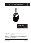
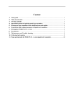
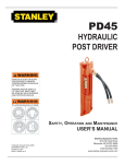
INTRODUCTION
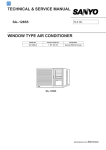
Part names and functions
02
Hook
Vacuum meter
VACUUM
Exhaust pressure
EXHAUST PRESSURE
Fuel pressure meter
P.S.I. (Pounds per square inch)
1kPa ≈ 0.145psi
1psi ≈ 6.895kPa
FUEL PRESSURE
FUEL SYSTEM ANALYZER
FUEL FLOW
3.5
0.8
0.6
0.7
0.5
0.6
2.5
2.0
0.4
1.5
Intake manifold
0.9
0.7
3.0
Fuel flowmeter
④
0.5
①
②
③
④
0.4
0.3
0.3
1.0
0.2
0.2
0.5
LITRES
0.1
0.1
U.S.
IMP.
GAL
GAL
PER MINUTE
IN
OUT
①
②
Quick connector
③
Fuel outlet pipe
Vacuum tubes
Fuel inlet pipe
03
T01-T04
M16A
M14B
F01
INTRODUCTION
Part names and functions
T05
S01/S02
M16B
M14A
The size of the
rubber ring:
● 11×1.9
● 6×1
M12B
F02/F03
F04
F05
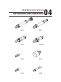
INTRODUCTION
Part names and functions
04
Z01
Z02
GM
FORD
B01
B02
K.
OT
9
11
V01
V02
05
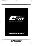
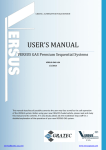
BASIC OPERATIONS
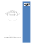
Fuel pressure / flow test
The connection method of the fuel system analyzer with
oil return line.
Distributor pipe
Fuel pressure regulator
Injector
Air intake manifold
Oil return line
Tank
Fuel filter
Supply pipe
Screen filter
Fuel pump
VACUUM
FUEL PRESSURE
FUEL SYSTEM ANALYZER
FUEL FLOW
3.5
0.9
0.7
3.0
0.7
0.5
0.6
2.0
0.4
1.5
0.8
0.6
2.5
0.5
0.4
0.3
0.3
1.0
0.2
0.2
0.5
LITRES
IN
0.1
0.1
U.S.
IMP.
GAL
GAL
PER MINUTE
OUT
Connect the fuel system analyzer follow the illustration.
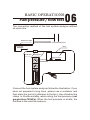
BASIC OPERATIONS
Fuel pressure / flow test
06
The connection method of the fuel system analyzer without
oil return line.
Distributor pipe
Fuel pressure regulator
Air intake manifold
Injector
Tank
Fuel filter
Supply pipe
Screen filter
Fuel pump
VACUUM
FUEL PRESSURE
FUEL SYSTEM ANALYZER
FUEL FLOW
3.5
0.9
0.7
3.0
0.7
0.5
0.6
2.0
0.4
1.5
0.8
0.6
2.5
0.5
0.4
0.3
0.3
1.0
0.2
0.2
0.5
LITRES
IN
0.1
0.1
U.S.
IMP.
GAL
GAL
PER MINUTE
OUT
Connect the fuel system analyzer follow the illustration. If you
have not prepared a long hose, please use a container and
then drain the fuel in it (attention to the fire). Use a flexible line
clamp to throttle suitably, while noting the fuel pressure. (not
greater than 700kPa). When the fuel pressure is at idle, the
fuel flow is the result to measure.
07
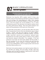
BASIC OPERATIONS
The EFI system
THE MAINTENANCE OF EFI SYSTEM
& DIAGNOSIS INFORMATION
Electronic fuel injection (EFI) system needs to have very
precise control for fuel pressure and flow. If pressure and flow
can not achieve the manufacturer's label, then engine
performance will be seriously affected or extreme cases will
occur, even the engine can not be started or run. In each
maintenance period, the electronic fuel injection system must
be under performance testing. This fuel system analyzer can
detect all the parameters of the electronic fuel system.
For abnormal fuel pressure, too low fuel flow (after the petrol
filter, the pipe flow in front of the fuel distribution pipe is about
2 liters / minute, with the fuel pressure of about 300kPa.
Different values are embodied in different models). Incorrect
intake manifold vacuum and excessive exhaust pipe
backpressure can both quickly detect a failure of the system
and provide relevant information. For example: if the fuel
pressure is too high, the three-way catalyst will be invalid; if
the fuel pressure is too low, the mixture gas will become
disproportionate. Issues related to mixture imbalance will
occur such as deflagration, lack of engine power valve burned
and other failures may occur.
Electronic fuel system analyzer can help fuel system failure to
be checked out rapidly and accurately, thereby improving
efficiency, and to avoid the waste of replacing the intact parts
caused by the miscarriage of justice.
BASIC OPERATIONS
The detection of EFI system
08
Electronic fuel injection system can be detected from the
following aspects:
●
●
●
●
●
●
Pressure and flow of oil supply system
Fuel control valve performance
Holding pressure of static system
Whether there is air resistance when system works
The vacuum degree of intake manifold
Backpressure of exhaust pipe (pressure before three-way
catalyst)
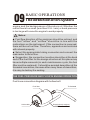
THE USE OF THE FUEL PRESSURE METER
● The main meter should be hung vertically under the hood or
vehicle.
● Main meter includes: fuel pressure gauge, fuel flow meter
and hose with a self-locking quick coupling.
● The fuel pressure meter has two scales units of kPa and
PSI, with the maximum detected pressure of 700kPa.
● On the flow scale, you can see through the two observation
windows. The front scale: l / min, the back of the scale: UK
gallons / min, and the United States gallons / min. From the
comparison chart on the panel, it is convenient for you to find
out the relationship among the British, American and metric
flow units.
● Fuel system analyzer is usually connected in series with
the vehicle oil line pipe, located on the back of the fuel filter,
and before the distribution pipe.
● For other tests, the instrument can be connected to the
return line between the fuel pressure regulator valve and the
fuel tank. In this position, the instrument will measure the fuel
consumption of the engine; check the back oil flow of the
09
BASIC OPERATIONS
The detection of EFI system
engine and the backpressure of the return oil. Whether the
return flow is too small (less than 0.5 L / min) or back pressure
is too large will cause the engine to work properly.
! Notes:
● Fuel flow direction of the analyzer should be noticed, and
the fuel "inflow" and "outflow" should be in line with the
instructions on the instrument. If the connection is reversed,
there will be no fuel flow. Therefore, apparatus and vehicles
will not work properly.
● Select the appropriate tubing connector and connect the
main meter to the oil line.
● Suggestion: the connection location should be at the back
end of the fuel filter for the design structure at this place may
have multiple removals (in each maintenance cycle, the fuel
filter must be replaced). It should be avoided demolition at the
threaded connection, because after many times of demolition,
it is easy to destroy the sealing.
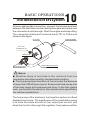
THE FUEL PRESSURE AND FLOW IN ENGINE OPERATION
Fuel hose connection diagram with hollow bolt:
Fuel filter
Hollow bolt
To fuel tank
Supply pipe(to engine)
BASIC OPERATIONS
The detection of EFI system
10
Choose appropriate connectors, connect fuel system analyzer
between the fuel filter and fuel distribution pipe and make sure
the connector is solid enough. Start the engine and keep idling.
The connection method of universal joints T01 to T04 are as
shown in the figure:
Fuel filter
供油管(至燃油箱)
T01-T04
To analyzer IN
Hollow bolt
T05
To analyzer OUT
Supply pipe(to engine)
! Notes:
● Whether there is fuel leak in the vehicle's fuel line
connection should be carefully checked before testing.
● The fuel pump flows two liters of fuel oil under the pressure
of more than 300 kPa per minute. Evena small leak spray mist
of fuel may cause a fire and personal injury. In the fuel system
work, we muststrictly adhere to the requirements specified by
the vehicle manufacturer.
The fuel pump of the electronic fuel injection system is a fixed
displacement pump. The significance of the quantitative pump
is to have the same amount of fuel output per minute, and
when the fuel oil is thorough the regulator, fuel pressure will be
11
BASIC OPERATIONS
The detection of EFI system
maintained under the throttle. The greater the throttle is, the
higher the fuel pressure will be. Fuel lines and hoses have
certain throttle effect, but the biggest throttling effect is
generated by the fuel pressure regulator. The fuel pressure
regulator regulates the throttling effect according to the vacuum
adjusting degree of the engine intake manifold, thus ensuring a
constant differential pressure across the injector, and leading to
that the fuel injection quantity is proportional to the open time of
the injector valve. Under normal circumstances, after the fuel
filter, the pressure before the stars tubing is about 300KPa
(3kg/cm 2 ) (different models are slightly different; there are
changes for idling, acceleration and different rotational speed);
the flow rate is 2 liters / minute (different models are slightly
different).
If the flow is lower than 1 L / min or pressure is not normal, it
indicates that the fuel system failure has occurred, or fuel
pump has serious wear and tear. The cause of the fault should
be checked out and excluded.
CHECK THE FUEL PRESSURE
After used for some time, the vehicle should have fuel pressure
detected. There may be different pressures for different vehicle
types. The specific values should be found in appropriate
maintenance manual.
● When idling operation occurs, the fuel pressure should be
consistent with the requirements of the vehicle manufacturer.
If the pressure is normal, flow lines of the main meter can be
partially clamped, to check whether the fuel pump can provide
enough pressure. When the hose is clamped, the pressure will
BASIC OPERATIONS
The detection of EFI system
12
rise. When the hose is completely clamped, the pressure will
increase to more than 1.5 times of the normal working pressure.
If the fuel pump can not meet the above requirements, it should
be replaced.
Tip: When using the tubing clamp around fuel pipe, the
pressure gauge should be observed. Do not make
pressure over 700kPa for too much pressure can damage
the vehicle or fuel system analyzer.
● If the fuel pressure is too low, the engine will not be started;
if there is no pressure or flow, it may be because that the fuel
pump is not working; if the pressure is too low or fuel flow is
much larger than the normal fuel flow, it may be because that
the regulator does not work at all. At this time, there is no
throttling effect in the return line of the fuel tank.
If the fuel pressure is too high (usually accompanied by a
decrease in fuel flow and the speed of the fuel pump speed is
reduced by high-pressure). There are two possible reasons:
●
Fuel pressure regulator has failure.
There is too large throttle in return line from the regulator to
the fuel tank.
◆
◆
For checking whether there is too large throttle from the
regulator to the fuel tank, steps are as follows:
Access the fuel system analyzer to the return line from the
regulator to the fuel oil tank, start the engine and make it begin
idle running. If the pressure exceeds about 15kPa, then there
is throttling effect in the return line to the fuel tank. Maybe it is
13
BASIC OPERATIONS
The detection of EFI system
because of bent tubing, that there is throttle for the rubber
hose tangles or fuel tank itself. With the height variations of
the fuel tank, the pressure in the return line also has small
changes.
● The pressure is normal for idle running, but the traffic is low.
Reasons may be the fuel pump itself, fuel filter clogged tubing
extruded or deformation. Tubing clamp can be used to
gradually grip the oil hose of the instrument. Observe the
change in pressure. If the pressure can increase to more than
1.5 times, then the fuel pump is normal. It can be judged from
the reasons of pump filter being clogged, fuel filter being
clogged or fuel tube being extruded to become deformation.
● Check the throttle valve. The throttle valve (pressure
regulating valve) adjusts the fuel pressure according to the
engine intake manifold vacuum, in order to maintain the
constant pressure differential at both ends of the injector.
When the throttle is suddenly opened widely, the vacuum
degree of the intake manifold will reduce quickly, that is,
increase in air pressure. The throttle valve is adjusted and the
fuel pressure is increased, with the variation range of 15 25kPa. If the throttle is opened or closed rapidly, but the fuel
pressure does not change, it means that there is failure for
throttle. The vacuum tube can also be unplugged at idle
running ( the other end should be clogged, to avoid leak).
Observe the change of the fuel pressure; or use a hand
vacuum pump to adjust the vacuum degree of the throttle
valve, and at the same time, observe the change of the fuel
pressure.
BASIC OPERATIONS
The detection of EFI system
14
CHECK THE FUEL FLOW
The fuel flow in the supply line of the engine is constant, which
is about 2 liters / min. Different models have various fuel flows,
which can be found from the corresponding repair manuals.
When the vehicles have been used for some time, due to
normal wear and tear of the fuel pump, the fuel flow will
decline, but if is too low, malfunction will be caused.
Tips: when measuring the fuel flow, fuel system analyzer
must be placed vertically, and use the hook in the upper of
the instrument to hook under the hood or other locations.
If the fuel flow is too low, the probable reasons may be as
follows:
The fuel pump is badly worn.
Throttle occurs for the fuel oil from the tank to the oil pump
(fuel pump filter of the fuel tank clogged).
● Throttle occurs for the fuel oil the pump to the engine fuel
(gasoline filter is clogged and tubing is extruded).
● The circuit failure connected to the oil pump cause too low
voltage of the oil pump and at this time, the pump speed is
lower than the normal speed.
●
●
The fuel oil flow back to the fuel tank:
If the fuel system analyzer is connected to the return line from
the pressure regulator to the tank, when the engine is
switched off and the fuel pump is operated (unplug the fuel
pump relay, and use jumper wires to have directly connection)
the fuel oil flow to the fuel tank will be the same with that to the
15
BASIC OPERATIONS
The detection of EFI system
fuel supply. If the engine works, the engine will consume a
portion of the fuel, and the fuel flowing into the fuel tank will be
reduced. The reduced part is the fuel consumed by the engine.
Under any load, the fuel oil flow retuning to the fuel tank can
not be less than 0.5 liters / min. If the fuel flow is less than 0.5
liters / min, it means that the lubrication system oil capacity
can not meet the needs of the engine working under heavy
load work. if it is still like this, after cleaning the fuel pump
strainer or replacing the fuel filter, the fuel pump should be
replaced.
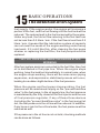
THE FUEL PRESSURE WHEN THE ENGINE STOPS
WORKING
After fuel system analyzer connected to the fuel filter, then fuel
oil is distributed in fuel pipe line. When the engine stops
working, have the leak test immediately. In normal case, when
the engine stops working, there will be some minor piping
expansion, and aspirated or stabilized process will occur,
leading to a sudden slight decline of the fuel pressure.
When the engine and fuel pump stops working, the fuel
pressure will be maintained relying on the "prevent backflow
valve" in the fuel pump. In the oil supply line, the fuel pressure
is maintained by the fully closed of the fuel injector and the use
of\ fuel pressure regulator. If any of these three devices
(including the "prevent backflow valve" in the fuel pump) let
out, the fuel pressure in the oil line will be reduced. In addition,
if any hose or joint in the oil line leaks, the fuel pressure will be
reduced as well.
If the pressure in the oil line is not on hold, checking methods
can be done as follows:
BASIC OPERATIONS
The detection of EFI system
16
● Check the one-way valve, and prevent oil return in the oil
pump.
Turn off the engine and fuel pump, using tubing clamp in the
supporting tool to clamp the oil outlet host of the fuel system
analyzer completely. At this time, what r detected by the fuel
system analyzes is the pressure on one side of the fuel pump
and it can be judged that the failure is the "prevent backflow
valve" of the fuel oil pump.
●
Check the leakage of the injector or the pressure regulator.
Remove the clamp of the inlet pipe on the fuel system
analyzer, re-start the engine, turn off the engine and clamp the
fuel oil system analyzer completely. At this time, what the
pressure gaga of fuel oil system analyzer detects the pressure
in the fuel line, while the fuel gauge is separated from the fuel
pump and the filter. If the pressure is lowered, it is judged that
one component of the injector and the regulator leaks. Using
the second sub-folder to clamp the return pipe from the
regulator into the tank completely, the pressure gauge will
detect the pressure in the whole supply line, while the oil
return line of the pressure regulator is disconnected. If the
pressure continues to drop, it can be judged that it is caused
by leakage from one or several injectors. If the pressure stops
decreasing, then it can be judged that the drop of the original
pressure is caused by the leakage of the internal regulator.
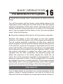
FUEL QUALITY
Fuel of high-quality is necessary for normal operation of the
engine. Under a certain pressure, the fuel oil is hard to be
observed for the air bubbles are compressed and its volume is
17
BASIC OPERATIONS
The detection of EFI system
small. In order to check the degree of gasoline vaporization,
the pressure gauge can be observed from the bubbles in the
flow meter tube, or it can be observed from pressure gauge at
the same time. When the fuel contains a certain amount of
gas, the pressure and flow will fluctuate in a small range,
rapidly and irregularly. Further examination: remove the fuel
pump insurance, start the engine, and reduce the fuel oil
pressure in the oil line. When the pressure in the oil line is
reduced, the bubbles will expand and it will become visible in
the flow meter tube. If it is found that the fuel oil has
vaporization problem, the problem may be due to the inhaled
air after the fuel pump filter clogged.
Fuel oil containing water can be judged from the tube of the
fuel meter, to see if there are phenomena of dirt or muddy.
When the fuel pump is closed, it can be judged from the
droplet in the flow meter tube.
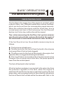
READINGS ON THE VACUUM METER
An experienced mechanic of engine can diagnose many faults
of engines from the readings of the vacuum gauge on the
intake manifold. For example: valve stuck, valve burned,
piston seal ring worn, valve guide rod worn or catheter worn,
rare of gas mixture and some other faults.
Connect the vacuum meter on the vacuum tube of the fuel
pressure regulator, (use the "vacuum test connector" in the
matching accessories. Observe the readings of the
vacuum/back pressure meter when observing the fuel
pressure meter. When the engine works in normal work
temperature, the correct vacuum degree of intake manifold
can refer to the service manual of corresponding models.
BASIC OPERATIONS
The detection of EFI system
18
If the readings on the vacuum gauge are not correct, then the
detection of the fuel system can not be conducted. Before
detecting, reasons causing bad vacuum should be excluded.
When the engine rotate speed is rapidly changed or the
engine is loaded, the vacuum degree of the intake manifold
and the fuel pressure will change at the same time. When the
vacuum varies from zero to a maximum, there will be changes
for the readings on the fuel gauge, vacuum gauge, and fuel
flow meter at the same time. If they do not change, there might
be fault for the fuel pressure regulator.
In order to evaluate the relationship between the degree of
vacuum and the fuel pressure, a manual vacuum pump can be
connected to the fuel pressure regulator's vacuum pipe, using
vacuum gauge to detect the vacuum degree, impacting a
vacuum of 40kPa or so, and then clamping the vacuum tube
connecting to the fuel pressure regulator. Pay attention to
whether the readings on the vacuum have been dropped. If
the readings on the vacuum gauge drop, it indicates that the
diaphragm of the fuel pressure regulator has been damaged,
and the fuel pressure regulator should be replaced.
Keep the engine at idling operation, and use manual vacuum
pump to change the degree of vacuum, while observing the
fuel gauge at the same time. when fuel pressure is normal, the
corresponding degree of vacuum should be -65kpa. And as
the increase of the vacuum degree, the fuel oil pressure will
decrease. The fuel oil pressure will be at maximum when the
vacuum degree is zero.
Remove the vacuum pipe from the fuel pressure regulator,
and check the vacuum tube which should have no fuel.
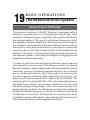
19
BASIC OPERATIONS
The detection of EFI system
EXHAUST BACK PRESSURE
The exhaust system of the EFI Engine is equipped with a
catalytic converter device. If fuel pressure is too high, it will
lead to too thick mixed gas, resulting in the unburned fuel into
the exhaust system. The result is to shorten the service life of
the catalytic converter apparatus. After long run for the engine,
the catalytic converter device in the exhaust system will be
blocked by coke and some debris, resulting in unsmooth
exhaust gas, so that the pressure will increase before the
catalytic converter. Through detecting the back pressure of
the exhaust system, it can judge the degree of clogging for the
catalytic converter apparatus.
In order to check the exhaust back pressure, back pressure
test connector can be used. The oxygen sensor or exhaust
gas recirculation valve located on the exhaust manifold can be
removed. Connect exhaust pressure meter to the exhaust
pipe or exhaust manifold. Start the engine to observe the
pressure gauge reading. When the engine is idling, the
pressure will not exceed 10 kPa. When it is at 2500rpm, the
pressure will not exceed 20 kPa. If the exhaust back pressure
exceeds these values, remove the catalytic converter, and
check the degree of blockage. If the conversion device is in
good working condition, throttling places should be furthered
located the exhaust system. In order to avoid the overheating
of detection connector, the back pressure test should be
completed quickly. Otherwise, it may damage the connector of
the component parts in the fuel system analyzer.
BASIC OPERATIONS
The detection of EFI system
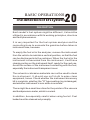
20
DESCRIPTION
Each model's fuel system might be different, it should be
utilized in accordance with its working principles, structure
and fault phenomenon.
It is very important for the fuel system analyzer and the
connecting hose to evacuate the gasoline before taken in
instrument case, because:
To empty the fuel oil in the analyzer, remove the instrument
from the vehicle to maintain a vertical position, so that the fuel
can be discharged into the container. When the fuel oil in the
instrument is evacuated from the instrument, it will have
cleaning action on the instrument itself, ready for the next use.
Avoid the surface of the instrument contacting with the fuel,
especially the instrument transparent cover.
The solvents or abrasive materials can not be used to clean
the instrument. It should use soft cloth to wipe clean
equipment, hoses. Check whether the instrument accessory
kit is complete, whether the "O" type sealing ring is damaged,
and whether instrument's zero-scale is accurate.
There might be a small zero bias for the pointer of the vacuum
and backpressure meter, which is normal.
In addition, be especially careful when using fuel oil. Fuel
leaked must be cleaned out promptly.
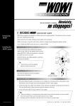
21
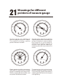
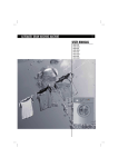
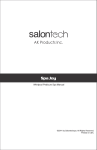
Meanings for different
pointers of vacuum gauge
60
60
40
8
40
8
6
10
6
10
4
80
20
12
4
80
20
12
2
-14
2
-14
P.S.I. 0
0
-100
P.S.I. 0
0
-100
kPa
kPa
VACUUM
VACUUM
Normal engine: the readings of
vacuum gauge are from 55- 70kPa.
The engine is at idling, and the
pointer indication is stable.
Normal engine: when the accelerator
is quickly turned on or turned off, the
pointer indication is down to 5kPa,
and vibration is around 80kPa,
followed by a smooth ring back to
normal idle speed readings,
indicating that the loop and valve is
normal.
60
60
40
8
40
8
6
10
6
10
4
80
20
12
4
80
20
12
2
-14
-14
P.S.I. 0
0
-100
2
P.S.I. 0
0
-100
kPa
kPa
VACUUM
VACUUM
Elastic weakening of the valve spring:
the engine is running fast, and the
pointer is vibrating in the range of 3070kPa; engine speed increases, and
the pointer vibrations increase
The delaying of the valve timing:
measure when the engine is running.
The pointer will remain silent when it
is among 30-50kPa when the engine
is in high idling.
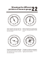
Meanings for different
pointers of vacuum gauge
60
60
40
8
40
8
6
10
22
6
10
4
80
20
12
4
80
20
12
2
-14
2
-14
P.S.I. 0
0
-100
P.S.I. 0
0
-100
kPa
kPa
VACUUM
VACUUM
Ignition delayed: when the operation
of the engine is at high idle, the
pointer will be fixed at some location
from 45 to 55kPa.
Misfire: If the pointer is moving slowly
from 47 to 52kPa, the spark plug gap
should be checked whether it is too
small.
60
60
40
8
40
8
6
10
6
10
4
80
20
12
4
80
20
12
2
-14
-14
P.S.I. 0
0
-100
2
P.S.I. 0
0
-100
kPa
kPa
VACUUM
VACUUM
The leak of intake system: When the
engine is running at idle or above idle,
and the pointer is from 10 to 15kPa,
the sealing of the intake manifold
should be checked.
The leak of cylinder head gasket
(leakage among each cylinder):
pointer moves forward or backward
regularly from 20 to 60kPa.
23
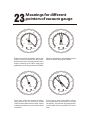
Meanings for different
pointers of vacuum gauge
60
60
40
8
40
8
6
10
6
10
4
80
20
12
4
80
20
12
2
-14
2
-14
P.S.I. 0
0
-100
P.S.I. 0
0
-100
kPa
kPa
VACUUM
VACUUM
Exhaust system blockage: when the
engine is launched for the first time,
the pointer value will fall back from a
higher reading to 0-5kPa, and then
gradually rise to the position of 50kPa.
Mixture imbalance: the pointer moves
back and forth among 45-55kPa.
60
60
40
8
40
8
6
10
6
10
4
80
20
12
4
80
20
12
2
-14
-14
P.S.I. 0
0
-100
2
P.S.I. 0
0
-100
kPa
kPa
VACUUM
VACUUM
Poor loop: when the engine is idling,
the pointer will be at some scale
10kPa lower than normal valve, which
indicates that there is poor lubrication
condition.
Poor loop or poor lubrication: when
the accelerator is turned on or turned
off rapidly, the pointer will swing back
to zero and rise to only 60kPa or even
less.
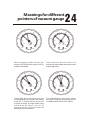
Meanings for different
pointers of vacuum gauge
60
60
40
8
40
8
6
10
24
6
10
4
80
20
12
4
80
20
12
2
-14
2
-14
P.S.I. 0
0
-100
P.S.I. 0
0
-100
kPa
kPa
VACUUM
VACUUM
Va l v e c l o g g i n g : w h e n a t i d l e , t h e
pointer will swing back about 12kPa
scales sometimes.
Va l v e b u r n e d : w h e n a t i d l e , t h e
pointer will swing back among several
scales regularly.
60
60
40
8
40
8
6
10
6
10
4
80
20
12
4
80
20
12
2
-14
-14
P.S.I. 0
0
-100
2
P.S.I. 0
0
-100
kPa
kPa
VACUUM
VACUUM
Valve leak: when the valve is in the
closed position, the pointer will swing
back for 7-10kPa scales; when the
engine is idling, a single spark plug
should be at short circuit, to
determine the cylinder that the
detected valve locates in.
The indication for valve worn: when
the engine is idling, the pointer will be
in rapid vibration from 47 to 62kPa.