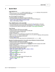
1
INTERFACE User manual UM EN PSI-MODEM3G/ROUTER Order No.: — Industrial 3G (UMTS/HSPA) mobile phone router with integrated firewall and VPN INTERFACE User manual Industrial 3G (UMTS/HSPA) mobile phone router with integrated firewall and VPN 2011-05-23 Designation: UM EN PSI-MODEM-3G/ROUTER Revision: 01 Order No.: — This user manual is valid for: Designation Revision Order No. PSI-MODEM-3G/ROUTER From 00 2314008 104672_en_01 PHOENIX CONTACT Please observe the following notes In order to ensure the safe use of the product described, you have to read and understand this user manual. The following notes provide information on how to use this user manual. User group of this manual The use of products described in this manual is oriented exclusively to PHOENIX CONTACT accepts no liability for erroneous handling or damage to products from PHOENIX CONTACT or third-party products resulting from disregard for the information contained in this user manual. Explanation of symbols used and signal words This is the safety alert symbol. It is used to alert you to potential personal injury hazards. Obey all safety measures that follow this symbol to avoid possible personal injury or death. DANGER This indicates a hazardous situation which, if not avoided, will result in death or serious injury. WARNING This indicates a hazardous situation which, if not avoided, could result in death or serious injury. CAUTION This indicates a hazardous situation which, if not avoided, could result in minor or moderate injury. The following types of messages provide information about possible property damage and general information concerning proper operation and ease-of-use. NOTE This symbol and the accompanying text alert the reader to a situation which may cause damage or malfunction to the device, hardware or software, or surrounding property. This symbol and the accompanying text provide the reader with additional information, such as tips and advice on the efficient use of hardware and on software optimization. It is also used as a reference to other sources of information (user manuals, data sheets). PHOENIX CONTACT General terms and conditions of use for technical documentation PHOENIX CONTACT reserves the right to alter, correct, and/or improve the technical documentation and the products described in the technical documentation at its own discretion and without giving prior notice, insofar as this is reasonable for the user. The same applies to any technical changes that serve the purpose of technical progress. The receipt of technical documentation (in particular data sheets, installation instructions, user manuals, etc.) does not constitute any further duty on the part of PHOENIX CONTACT to furnish information on alterations to products and/or technical documentation. Any other agreement shall only apply if expressly confirmed in writing by Phoenix Contact. Please note that the supplied documentation is product-specific documentation only and that you are responsible for checking the suitability and intended use of the products in your specific application, in particular with regard to observing the applicable standards and regulations. Although PHOENIX CONTACT makes every effort to ensure that the information content is accurate, up-to-date, and state-of-the-art, technical inaccuracies and/or printing errors in the information cannot be ruled out. Phoenix Contact does not offer any guarantees as to the reliability, accuracy or completeness of the information. All information made available in the technical data is supplied without any accompanying guarantee, whether expressly mentioned, implied or tacitly assumed. This information does not include any guarantees regarding quality, does not describe any fair marketable quality, and does not make any claims as to quality guarantees or guarantees regarding the suitability for a special purpose. Phoenix Contact accepts no liability or responsibility for errors or omissions in the content of the technical documentation (in particular data sheets, installation instructions, user manuals, etc.). The aforementioned limitations of liability and exemptions from liability do not apply, in so far as liability must be assumed, e.g., according to product liability law, in cases of premeditation, gross negligence, on account of loss of life, physical injury or damage to health or on account of the violation of important contractual obligations. Claims for damages for the violation of important contractual obligations are, however, limited to contract-typical, predictable damages, provided there is no premeditation or gross negligence, or that liability is assumed on account of loss of life, physical injury or damage to health. This ruling does not imply a change in the burden of proof to the detriment of the user. PHOENIX CONTACT Statement of legal authority This manual, including all illustrations contained herein, is copyright protected. Use of this manual by any third party is forbidden. Reproduction, translation, and public disclosure, as well as electronic and photographic archiving and modification require written consent by Phoenix Contact. Violators are liable for damages. PHOENIX CONTACT reserves all rights in the case of patent award or listing of a registered design. Third-party products are always named without reference to patent rights. The existence of such rights shall not be excluded. How to contact us Internet Up-to-date information on PHOENIX CONTACT products and our Terms and Conditions can be found on the Internet at: www.phoenixcontact.com. Make sure that you are always working with the current documentation. It can be downloaded at: www.phoenixcontact.net/catalog. Subsidiaries If there are any problems that cannot be solved using the documentation, please contact your Phoenix Contact subsidiary. Subsidiary contact information is available at www.phoenixcontact.com. Published by PHOENIX CONTACT GmbH & Co. KG Flachsmarktstraße 8 32825 Blomberg DEUTSCHLAND Telefon +49 - (0) 52 35 - 3-00 Telefax +49 - (0) 52 35 - 3-4 12 00 Should you have any suggestions or recommendations for improvement of the contents and layout of our manuals, please send your comments to: [email protected] PHOENIX CONTACT Table of contents 1 2 3 Description of the 3G router .....................................................................................................1-1 1.1 Description .........................................................................................................1-1 1.2 Ordering data ..................................................................................................... 1-2 1.3 Technical data .................................................................................................... 1-2 Hardware Installation ...............................................................................................................2-1 2.1 Housing dimensions ...........................................................................................2-1 2.2 Mounting the module on a DIN rail .....................................................................2-1 2.3 Description of the connections and LEDs ........................................................... 2-2 2.4 Establishing connections.................................................................................... 2-3 2.4.1 Safety notes .................................................................................... 2-3 2.4.2 Connecting Ethernet networks .......................................................... 2-4 2.4.3 Connecting the antenna ...................................................................... 2-5 2.4.4 Inserting the SIM card .......................................................................2-6 2.4.5 Connecting the supply voltage ............................................................2-8 2.4.6 Connecting switching inputs and outputs ............................................ 2-9 2.4.7 Resetting the router ............................................................................ 2-9 Configuration via WBM ............................................................................................................3-1 104672_en_01 3.1 Connection requirements ...................................................................................3-1 3.2 Starting web-based management (WBM) .......................................................... 3-1 3.3 Device Information (View device status)............................................................. 3-2 3.3.1 Hardware ............................................................................................ 3-2 3.3.2 Software ..............................................................................................3-3 3.3.3 Status .................................................................................................. 3-4 3.4 Local Network (Set up local network) ................................................................. 3-8 3.4.1 IP Configuration (Set up connection) .................................................. 3-8 3.4.2 DHCP Server .................................................................................... 3-10 3.4.3 Static Routes .................................................................................... 3-11 3.4.4 SNMP Configuration ......................................................................... 3-12 3.5 Wireless Network (Mobile phone settings) .......................................................3-13 3.5.1 Radio Setup ......................................................................................3-13 3.5.2 SIM ................................................................................................... 3-15 3.5.3 Backup SIM ......................................................................................3-17 3.5.4 SMS Configuration (SMS settings) ................................................... 3-19 3.5.5 Packet Data Setup ............................................................................ 3-21 3.5.6 Wireless Static Routes ...................................................................... 3-22 3.5.7 DynDNS ............................................................................................3-23 3.5.8 Connection Check ............................................................................ 3-24 3.6 Network Security (Security settings)................................................................. 3-25 3.6.1 General Setup ...................................................................................3-25 3.6.2 Firewall (Definition of firewall rules) ................................................... 3-26 3.6.3 NAT Table (setting port forwarding) ..................................................3-29 PHOENIX CONTACT i PSI-MODEM-3G/ROUTER 4 5 ii 3.7 VPN ..................................................................................................................3-31 3.7.1 IPsec Connections (IPsec connection setup) ....................................3-32 3.7.2 IPsec Certificates (Certificate upload) ...............................................3-38 3.7.3 IPsec Status (Status of the VPN connection) ................................... 3-41 3.7.4 OpenVPN Client (Create OpenVPN connections) ............................ 3-42 3.7.5 OpenVPN Certificates (Certificate upload) ........................................ 3-44 3.7.6 OpenVPN Status (VPN connection status) .......................................3-45 3.8 I/O.....................................................................................................................3-46 3.8.1 Inputs (Configuring inputs) ................................................................3-46 3.8.2 Outputs (Configuring outputs) ........................................................... 3-48 3.8.3 Phonebook ....................................................................................... 3-49 3.8.4 Socket Server ...................................................................................3-50 3.9 System .............................................................................................................3-52 3.9.1 User (Password modification) ........................................................... 3-52 3.9.2 Log Configuration ............................................................................. 3-53 3.9.3 Log File ............................................................................................. 3-54 3.9.4 SMTP Configuration .......................................................................... 3-55 3.9.5 Configuration Up-/Download .............................................................3-56 3.9.6 RTC (Time and date setup) ............................................................... 3-57 3.9.7 Reboot (Router restart) .....................................................................3-59 3.9.8 Firmware Update ..............................................................................3-60 3.10 CIDR (Classless Inter-Domain Routing) ........................................................... 3-61 Creating certificates .................................................................................................................4-1 4.1 Installing XCA ..................................................................................................... 4-1 4.2 Creating a database ...........................................................................................4-1 4.3 Creating a CA certificate.....................................................................................4-3 4.4 Creating machine certificates .............................................................................4-7 4.4.1 Creating templates .............................................................................. 4-7 4.4.2 Creating machine certificates based on a template ...........................4-11 4.4.3 Exporting machine certificates ..........................................................4-14 Application examples...............................................................................................................5-1 PHOENIX CONTACT 5.1 Internet access ...................................................................................................5-1 5.1.1 Before you begin ................................................................................. 5-1 5.1.2 Setting up the PSI-MODEM-3G/ROUTER .......................................... 5-2 5.2 Safe VPN connections to FL MGUARD.............................................................. 5-4 5.2.1 Before you begin ................................................................................. 5-4 5.2.2 Network overview ............................................................................... 5-5 5.2.3 Creating certificates ............................................................................ 5-6 5.2.4 Loading certificates in the router .........................................................5-6 5.2.5 Setting up the VPN connection on the modem .................................... 5-8 5.2.6 Configuring the FL MGUARD RS VPN .............................................. 5-10 104672_en_01 Table of contents 5.2.7 5.2.8 5.2.9 5.3 104672_en_01 Loading certificates on the FL MGUARD RS VPN ............................ 5-11 Setting a packet filter on the FL MGUARD RS VPN .......................... 5-13 Setting up the RS VPN in the FL MGUARD ......................................5-14 Virtual Ethernet dedicated line.......................................................................... 5-17 5.3.1 Before you begin ............................................................................... 5-17 5.3.2 Network overview ............................................................................. 5-18 5.3.3 Creating certificates .......................................................................... 5-18 5.3.4 Loading certificates in the client router (Device "A") .......................... 5-19 5.3.5 Setting up the VPN connection in the client router ............................ 5-21 5.3.6 Loading certificates in the server router (Device "B") ........................5-23 5.3.7 Setting up the VPN connection on the server router .......................... 5-25 PHOENIX CONTACT iii PSI-MODEM-3G/ROUTER iv PHOENIX CONTACT 104672_en_01 Description of the 3G router 1 Description of the 3G router 1.1 Description The 3G router PSI-MODEM-3G/ROUTER is a high-performance router for industrial Ethernet networks which can be used to securely transmit sensitive data via GSM networks. The integrated firewall and the VPN support (Virtual Private Network) protect your application against unauthorized access. A UMTS/HSPA connection simply incorporates remote stations into an IP network. If UMTS/HSPA is not available, the system automatically switches to GPRS/EDGE. Regardless of where your system or controller is situated, you can access the process data via a secure VPN connection from any location. EMC, electrical isolation and surge protection are provided for reliable and secure communication. The data link and cell phone network quality are also monitored. If necessary, an appropriate message is sent or the cell phone connection re-established. Six configurable switching inputs allow the user to independently send an SMS or e-mail both to one or several recipients. Four integrated switching outputs can be activated using a password-protected SMS message. The system status can thereby be monitored and functions switched remotely. Features – – – – – – – – – – – – – – – 104672_en_01 UMTS/HSPA tri-band (850 MHz/1900 MHz/2100 MHz) GPRS/EDGS quad-band (850 MHz/900 MHz/1800 MHz/1900 MHz) GPRS (General Packet Radio Service), EDGE (Enhanced Data Rates for GSM Evolution) and UMTS (Universal Mobile Telecommunications System) Second SIM card slot for backup mobile phone network Virtual dedicated line to connect networks via cell phone network Integrated firewall IPsec and OpenVPN support VPN remote start via SMS or call Configurable inputs and outputs Alarming by SMS, e-mail or fax directly via integrated switching input Further supply voltage range of 10 V DC ... 30 V DC Temperature range of -25°C ... +65°C High-quality electrical isolation (VCC // UMTS // Ethernet // PE) Integrated surge protection Easy configuration via web-based management (WBM) PHOENIX CONTACT 1-1 PSI-MODEM-3G/ROUTER 1.2 Ordering data Router Description Type Order No. Pcs. / Pkt. PSI-MODEM-3G/ROUTER 2314008 1 Type Order No. Pcs. / Pkt. PSI-GSM/UMTS-QB-ANT 2313371 1 GSM-UMTS omnidirectional antenna, 2 dBi boost, 5 m antenna cable with SMA round connector PSI-GSM/UMTS-ANT-OMNI-2-5 2900982 1 GSM/UMTS antenna cable, 10 m long; SMA (male) -> SMA (female), 50 Ohm impedance PSI-CAB-GSM/UMTS-10M 2900981 1 GSM/UMTS antenna cable, 5 m long; SMA (male) -> SMA (female), 50 Ohm impendance PSI-CAB-GSM/UMTS- 5M 2900980 1 System power supply, primary switched Input voltage range Nominal output voltage Nominal output current MINI-SYS-PS-100-240AC/24DC/1.5 2866983 1 UMTS/HSPA cell phone router with Ethernet interface, firewall, VPN support and alarm inputs and outputs Accessories Description GSM-UMTS antenna with omnidirectional characteristics, antenna cable with SMA round connector Degree of protection Dimensions 2m IP65 76 mm x 20 mm 45 Hz ... 65 Hz 85 V AC ... 264 V AC 24 V DC ±1% 1.5 A 1.3 Technical data Supply Supply voltage 10 V DC ... 30 V DC via plug-in COMBICON screw terminal block Frequency DC Current consumption Nominal current consumption < 200 mA at 24 V, < 580 mA at 10 V Standby current consumption < 90 mA at 24 V LED display Power (green LED) Steady light: Operation Ethernet interface Connection method RJ45 female connector, shielded Transmission speed 10/100 Mbps Transmission distance 100 m (twisted pair, shielded) Supported protocols TCP/IP, UDP/IP, FTP, HTTP Secondary protocols ARP, DHCP, PING (ICMP), SNMP V1, SMTP LED display/control signal indicator ACT (yellow LED), Ethernet data transmission LINK (green LED), Ethernet link established Function Management 1-2 PHOENIX CONTACT Web-based management, SNMP 104672_en_01 Description of the 3G router Mobile phone network UMTS frequencies 850 MHz, 1900 MHz, 2100 MHz (UMTS/HSPA) Transmission power 0.25 W UMTS compatibility UMTS/HSPA 3GPP release 6 – HSUPA max. 5.76 Mbps – HSDPA max. 7.2 Mbps SIM Interface 2 interfaces, 1.8-volt and 3-volt SIM card GSM frequencies 850 MHz, 900 MHz, 1800 MHz, 1900 MHz (GPRS/EDGS) GPRS compatibility GPRS Class 12, Class B Coding diagrams: CS1 ... CS4 EDGE EDGE (E-GRPS) Multislot Class 10 Network function 4 time slots for receiving data 4 time slots for sending data, maximum of 5 time slots at any one time The PIN code is stored in the router. After a voltage interrupt, the system automatically logs back into the network and the GPRS network. Integrated TCP/IP stack, firewall and VPN support, automatic connection establishment. Antenna connection 50 Ω impedance SMA female antenna connector LED SIM (green LED) – Steady light: SIM card active – Flashing: No PIN code entered – Off: SIM card inactive or not available NET (LED bar graph) Switch-on diagnostics Self-test, visualization via LEDs (controller, RAM, EPROM, GSM engine, antenna, EEPROM) Network check Network bar graph in web-based management Switching inputs and outputs Switching inputs 6 x Unom 24 V DC / 5 mA, Input range 10 V DC ... 30 V DC input voltage range, activates one or more of the following: – SMS – E-mail – Output activation on remote station (via SMS) – Reboot, GPRS/EDGE, VPN Switching outputs 4 x Unom 24 V DC / 50 mA, Input range 10 V DC ... 30 V DC, short-circuit-proof activated by: – Activation of remote station input – SMS – Web-based management – GSM, GPRS/EDGE, VPN, incoming call and connection abort Signaling ALR (red LED) Ambient conditions Ambient temperature range (operation) -25°C ... +65°C not aligned, -25°C ... +60°C aligned Ambient temperature range (storage/transport) -40°C ... +75°C General data Housing ME 45 with ground contact Material PA 6.6-FR, V0, green Dimensions (W x H x D) 99 mm x 45 mm x 114.5 mm Device weight 226 g Functional earth ground Housing contact to DIN rail Degree of protection IP 20 Separate ground levels VCC // UMTS // Ethernet // PE 104672_en_01 PHOENIX CONTACT 1-3 PSI-MODEM-3G/ROUTER General data [...] Vibration resistance According to DIN EN 60068-2-6 5 g, per 1.5 h in x-, y-, z-direction Shock testing According to DIN EN 60068-2-27 Operation 15 g, 11 ms, half-sine shock pulse Bearings 30 g, 11 ms, half-sine shock pulse Free fall According to IEC 60068-2-32 from height of 1 m (unpacked) Test voltage 500 V AC, 50 Hz, 1 min. between all potential levels according to DIN EN 61010-1 / VDE 0411-1 and DIN EN 60950 CE conformance According to R&TTE Directive 1999/5/EC Electromagnetic compatibility Noise immunity according to EN 61000-6-2 Electrostatic discharge (ESD) EN 61000-4-2 Criterion B 8 kV air discharge 4 kV contact discharge Electromagnetic RF field EN 61000-4-3 Amplitude modulation 10 V/m Pulse modulation Fast transients (burst) Criterion A 10 V/m EN 61000-4-4 Signal Criterion A 1 kV / 5 kHz Supply Criterion A 1 kV / 5 kHz Criterion B 1 kV / 5 kHz Surge current loads (surge) EN 61000-4-5 Signal Criterion B 1 kV Supply 1 kV symmetrical, 2 kV symmetrical Conducted influence EN 61000-4-6 Criterion A Noise emission EN 55011 Class A 10 V CE conformance according to R&TTE Directive 1999/5/EC EMC Immunity to interference (electromagnetic compatibility) Safety Personal protection in terms of electrical safety Health Limiting exposure to electromagnetic fields EN 61000-6-2 Specialized standard for industry EN 60950 Official Journal of the European Communities 1999/519/EC Recommendation of the Council of the European Community from July 12, 1999 Radio Effective use of frequency range and avoidance of technical radio interference DIN EN 301511 Approvals UL, USA/Canada 1-4 PHOENIX CONTACT In progress 104672_en_01 Hardware Installation 2 Hardware Installation 2.1 Housing dimensions 45 99 POWER VPN ALR RESET LAN 114,5 NET ANT 3G PD SIM1 SIM2 PSI-MODEM-3G/ROUTER Ord.-No.2314008 Figure 2-1 2.2 Housing dimensions (in mm) Mounting the module on a DIN rail NOTE: Only mount and remove the router when the power supply is disconnected. NOTE: The DIN rail must be connected to PE to ensure safe operation. Mount the router on a 35 mm EN DIN rail. Figure 2-2 104672_en_01 Mounting PHOENIX CONTACT 2-1 PSI-MODEM-3G/ROUTER 2.3 Description of the connections and LEDs Connection terminal blocks 1 2 1 Connection terminal blocks (COMBICON): 24 V supply, 0 V supply 2 6 switching inputs, digital 4 4 switching outputs, digital 3 SMA female antenna connector 5 RJ45, Ethernet interface (TP port) 6 Reset button Connectors 6 POWER VPN ALR RESET 5 LAN NET 3 ANT LEDs 3G PD SIM1 SIM2 PSI-MODEM-3G/ROUTER Ord.-No.2314008 2 4 Power (green) Steady light if supply voltage is present VPN (green) VPN tunnel active ALR (red) On when there is an alarm event on one of the inputs. NET (yellow, green, green) yellow, green, green with very good network reception yellow, green with good network reception yellow with sufficient network reception Off when no or very poor network reception 3G (green) UMTS/HSPA connection active PD (green) Packet data connection active SIM 1/2 (green) On when SIM card 1/2 active Flashes if no PIN code entered On the back SIM card holder 2-2 PHOENIX CONTACT 104672_en_01 Hardware Installation 2.4 2.4.1 Establishing connections Safety notes WARNING: Electrical connection may only be carried out by qualified personnel The electrical connection, startup and operation of this device may only be performed by qualified personnel. With respect to the safety notes of this document, qualified personnel are persons who are authorized to start up, to ground, and to mark devices, systems, and equipment according to the standards of safety technology. In addition, these persons must be familiar with all warning instructions and maintenance measures in this text. Disregarding this warning may result in damage to equipment and/or serious personal injury. WARNING: SELV operation The PSI-MODEM-3G/ROUTER is exclusively designed for the operation in the control cabinet and for connecting with the safety extra-low voltage (SELV) in accordance with IEC 60950 / EN 60950 / VDE 0805. WARNING: The router must only be connected to devices which meet the requirements of EN 60950 (Safety of Information Technology Devices). WARNING: Disconnect the device power supply before replacing the SIM card The device only supports 1.8 and 3 V SIM cards. For older SIM cards, please contact your GSM service provider. 104672_en_01 PHOENIX CONTACT 2-3 PSI-MODEM-3G/ROUTER 2.4.2 Connecting Ethernet networks WARNING: Disconnect the device power supply before replacing the SIM card The router must only be connected to devices which meet the requirements of EN 60950 (Safety of Information Technology Devices). NOTE: Only use shielded twisted pair cables and matching shielded RJ45 connectors. The PSI-MODEM-3G/ROUTER has an Ethernet interface on the front in RJ45 format, to which only twisted pair cables with an impedance of 100 Ω can be connected. Plug the Ethernet cable with the crimped RJ45 connector into the TP interface until the connector engages audibly. Observe the connector keying. n .c . P in 8 n .c . P in 7 T D - P in 6 n .c . P in 5 n .c . P in 4 T D + P in 3 R D - P in 2 R D + P in 1 Figure 2-3 2-4 PHOENIX CONTACT R J 4 5 RJ45 interface 104672_en_01 Hardware Installation 2.4.3 Connecting the antenna 24 V 0V I1 I2 T NE R WE PO N VP R AL T SE RE N LA T AN 3G PD 1 SIM 2 SIM /RO -3G DEM 8 MO 1400 PSI- No.23 .Ord Figure 2-4 1. 2. R UTE Antenna connection with SMA connector Connect a suitable antenna to the antenna connection. If the "NET" bar graph indicates good (yellow, green) or very good (yellow, green, green) reception, secure the antenna. Installing the antenna 1. 2. Select an antenna position with a good wireless network signal. The "NET" bar graph can be used to determine the receive quality. When using the PSI-GSM/UMTS-QB-ANT antenna (Order No. 2313371), drill a hole measuring 16.5 mm in diameter in the top of the control cabinet. NOTE: Please observe the following during installation: – The antenna has a diameter of 76 mm and is 21 mm high. – The cable is 2 meters long. 104672_en_01 PHOENIX CONTACT 2-5 PSI-MODEM-3G/ROUTER 3. Secure the antenna using the washer and nut provided: 102678A005 Figure 2-5 2.4.4 PSI-GSM/UMTS-QB-ANT antenna installation Inserting the SIM card WARNING: Disconnect the device power supply before replacing the SIM card The device only supports 1.8 and 3 V SIM cards. For older SIM cards, please contact your GSM service provider. NOTE: Electrostatic discharge The device contains components that can be damaged or destroyed by electrostatic discharge. When handling the device, observe the necessary safety precautions against electrostatic discharge (ESD) according to EN 61340-5-1 and EN 61340-5-2 and IEC 61340-5-1. Remove SIM card holder A B 1. 2. 2-6 PHOENIX CONTACT Push the yellow release button with a pointed object. Remove the SIM card holder. 104672_en_01 Hardware Installation Inserting the SIM card You receive a SIM card from the GSM provider, on which all data and services for your connection are stored. C D 1. 2. PIN code Insert the SIM card so that the SIM chip remains visible. Fully insert the SIM card holder together with the SIM card into the device until this ends flush with the housing. The SIM card can be protected with a 4 or 5-digit PIN code. It is recommended that you enter the PIN code as described in Section "SIM" on page 3-15. When selecting the SIM card, please note that a packet data connection (GPRS or EDGE) is required for the core functions (VPN router). 104672_en_01 PHOENIX CONTACT 2-7 PSI-MODEM-3G/ROUTER 2.4.5 Connecting the supply voltage WARNING: SELV operation The PSI-MODEM-3G/ROUTER is exclusively designed for the operation in the control cabinet and for connecting with the safety extra-low voltage (SELV) in accordance with IEC 60950 / EN 60950 / VDE 0805. The supply voltage should be 10 V DC ... 30 V DC. 1. Connect the supply voltage to the plug-in screw terminal block to 24 V and 0 V. Observe the polarity. 2. The device is ready for operation as soon as the power LED lights up. 24 V 0V I1 I2 NE W PO N VP R AL RE SE LA T ER N AN T T 3G PD 1 SIM 2 SIM UTER RO -3G/ EM OD 14008 PSI-M-No.23 Ord. Figure 2-6 2-8 PHOENIX CONTACT Connecting the supply voltage 104672_en_01 Hardware Installation 2.4.6 Connecting switching inputs and outputs – + 24V 0V I1 I2 Figure 2-7 1. 2. Wiring the inputs Connect the switching inputs and outputs to the relevant plug-in screw terminal blocks. – To the switching inputs (I1 ... I6) you can connect 10 ... 30 V DC. – The short-circuit-proof switching outputs (O1 ... O4) are designed for max. 50 mA at 10 ... 30 V DC. You must connect the 0 V potential of the switching inputs and outputs to the "0 V" terminal of the voltage supply connection. 2.4.7 Resetting the router The router has a reset button (Position 6 in "Description of the connections and LEDs" on page 2-2), for resetting the router's IP address in the default upon delivery. 1. Press and hold down the reset button (6). 2. Disconnect the Ethernet cable from the LAN connection on the router. 3. Reconnect the Ethernet cable. 4. Press and hold down the reset button for another 5 seconds. The IP address is reset to the setting default upon delivery. The router can be accessed at 192.168.0.1. 104672_en_01 PHOENIX CONTACT 2-9 PSI-MODEM-3G/ROUTER 2-10 PHOENIX CONTACT 104672_en_01 Configuration via WBM 3 Configuration via WBM 3.1 – – – Connection requirements The router PSI-MODEM-3G/ROUTER must be connected to the power supply. The computer that is to be used for configuration must be connected to the LAN female connector on the router. A browser (e.g., Mozilla Firefox, Microsoft Internet Explorer or Apple Safari) must be installed on the configuration computer. 3.2 Starting web-based management (WBM) The PSI-MODEM-3G/ROUTER is configured via web-based management (WBM). 1. Establish an Ethernet connection from the PSI-MODEM-3G/ROUTER to a PC. 2. Open a browser on the PC. 3. Set the IP address of your PC to the network of the router. 4. Enter the IP address 192.168.0.1 in the address field of your browser. The following page opens in the browser. Figure 3-1 Login window This page protects the area in WBM where router settings are modified. A user name and password are required in order to log in. – The user name is "admin" and the password is "admin". For security reasons, we recommend you change the password during initial configuration (see "User (Password modification)" on page 3-52). 104672_en_01 PHOENIX CONTACT 3-1 PSI-MODEM-3G/ROUTER There are two user levels: – User: Read-only access to the "Device Information" menu item – Admin: Full access to all areas. To configure the router, make the desired settings on the individual pages of the router user interface. 3.3 Device Information (View device status) This area can be accessed with the "User" login and displays information about the hardware, software, and status of the router. 3.3.1 Hardware Device Information >> Hardware Hardware 3-2 PHOENIX CONTACT Address Address of the manufacturer Internet Internet address of the manufacturer Type Router order designation Order No. Router order number Serial Number Router serial number Hardware Router hardware version Release Version Router software release version Operating System Operating system version Web-Based Management Version of web-based management 104672_en_01 Configuration via WBM Device Information >> Hardware [...] MAC Address The MAC address enables the unique identification of an Ethernet device in a computer network. Radio Engine Type of mobile phone module used Radio Firmware Mobile phone module firmware version IMEI The IMEI (International Mobile Station Equipment Identity) is a 15-digit serial number that can be used to clearly identify each GSM or UMTS termination device. 3.3.2 Software All installed software modules with version codes are listed under this menu item. 104672_en_01 PHOENIX CONTACT 3-3 PSI-MODEM-3G/ROUTER 3.3.3 Status Current status information about the GSM network and the network connections is displayed here. 3.3.3.1 Radio Device Information >> Status >> Radio Radio Status Provider Provider name Network Status Status of the mobile phone network Registered home: Logged into the provider's home network Roaming: Dial-in into an external mobile phone network Waiting for PIN: Enter PIN Waiting for PUK: SIM card locked because PIN given incorrectly 3 x, PUK entry required Wrong PIN: Wrong PIN stored in device No SIM Card: Insert SIM card Power off: GSM module has not yet started Signal Level 3-4 PHOENIX CONTACT Signal strength as a dBm value and bar 104672_en_01 Configuration via WBM Device Information >> Status >> Radio [...] Packet Data Offline: There is no packet data connection in the mobile phone network. GPRS online: There is an active packet data connection in the mobile phone network via GPRS. GPRS is a GSM service, which provides packet-based wireless access for mobile GSM users. EDGE online: There is an active packet data connection in the mobile phone network via EDGE. EDGE is a further development of the GPRS data service with a higher data transmission rate. UMTS online: There is an active high-speed packet data connection in the 3G mobile phone network via UMTS. HSDPA/UPA online: There is an active high-speed packet data connection in the 3G mobile phone network via HSDPA/UPA. HSDPA/UPA is a further development of the UMTS network with a higher data transmission rate. 104672_en_01 Local Area Code Area code within mobile phone network Cell ID Unique mobile phone cell ID PHOENIX CONTACT 3-5 PSI-MODEM-3G/ROUTER 3.3.3.2 Network Connections The "Network Connections" page displays status information about the local Ethernet interface and the packet data interface in the mobile phone network. Device Information >> Status >> Network Connections Network Connections Wireless Network Link TCP/IP connected: There is an active packet data connection in the mobile phone network. Data can be transmitted via TCP/IP. VPN connected: There is an active VPN connection in the mobile phone network. Encrypted data can be transmitted. Not connected: There is no packet data connection in the mobile phone network, so no data can be transmitted. IP Address IP address assigned by the provider Netmask Netmask assigned by the provider DNS server IP address of the DNS server Sec. DNS server IP address of the alternative DNS server RX bytes Sum of data received since the last login to mobile phone network TX bytes Sum of data sent since last login to mobile phone network Local Network Link 3-6 PHOENIX CONTACT The local Ethernet is connected (connected)/is not connected (not connected). IP Address Current Ethernet IP address Netmask Netmask of the local Ethernet network 104672_en_01 Configuration via WBM 3.3.3.3 I/O Status Current status information and input and output configurations are displayed on the "I/O Status" page. 3.3.3.4 Routing Table All routing table entries are displayed here. 104672_en_01 PHOENIX CONTACT 3-7 PSI-MODEM-3G/ROUTER 3.4 3.4.1 Local Network (Set up local network) IP Configuration (Set up connection) The connection from the router to the local Ethernet computer can be set up here. The IP configuration can also be modified here. The IP address, subnet mask, and the type of address assignment can be set. Changes to the router's IP configuration are automatically adopted after restarting. Changed IP configurations can be stored manually by following these steps: 1. Press and hold down the "Reset" button. 2. Remove Ethernet cable. 3. Release the Reset button. 4. Plug the Ethernet cable back in. Local Network >> IP Configuration IP Configuration Current Addresses IP Address Current IP address of the computer that is connected to the router's TP interface. You can use the Reset button to reset the IP address to the default address 192.168.0.1 (see "Resetting the router" on page 2-9). Subnet mask 3-8 PHOENIX CONTACT The subnet mask for the current IP address. 104672_en_01 Configuration via WBM Local Network >> IP Configuration [...] Type of IP address assignment Static (default): The IP address is assigned permanently (fixed IP). DHCP: When the router is started, the IP address and the subnet mask are assigned dynamically by a DHCP server. Alias Addresses 104672_en_01 With the help of the Alias Addresses, up to 8 additional IP addresses can be assigned to the router. This way, the router can be reached via different subnetworks. Enter the desired IP address and subnet mask. PHOENIX CONTACT 3-9 PSI-MODEM-3G/ROUTER 3.4.2 DHCP Server The Dynamic Host Configuration Protocol (DHCP) can be used to automatically assign the network configuration set here to the devices connected directly to the router. Local Network>> DHCP Server DHCP Server DHCP Server Deactivated/Activated Set the switch to "Enable" when the router should work as a DHCP server. Domain Name Enter a domain name that will be distributed via DHCP. Lease Time (d,h,m,s) Time for which the network configuration assigned to the client is valid. The client should renew its assigned configuration shortly before this time elapses. Otherwise it may be assigned to other computers. Dynamic IP address allocation Dynamic IP address pool: When the DHCP server and the dynamic IP address pool have been activated, you can specify the network parameters to be used by the client. Begin IP Range Start of DHCP area: The start of the address area from which the DHCP server should assign IP addresses to locally connected devices. End IP Range End of DHCP area: The end of the address area from which the DHCP server should assign IP addresses to locally connected devices. Static IP address allocation Static assignment [based on the MAC address]: The client's static IP to which the MAC address should be assigned. Client MAC Address 3-10 PHOENIX CONTACT Client's MAC-address (with hyphens) 104672_en_01 Configuration via WBM Local Network>> DHCP Server [...] Client IP Address Client IP address Static assignments must not overlap with the dynamic IP address pool. Do not use one IP address in multiple static assignments, otherwise multiple MAC addresses will be assigned to this IP address. 3.4.3 Static Routes With local, static routes, alternative routes can be established for data packets from the local network via other gateways in overlapping networks. Local Network>> Static Routes Static Routes 104672_en_01 Network Network in CIDR format - see "CIDR (Classless Inter-Domain Routing)" on page 3-61 Gateway The gateway via which this network can be accessed. PHOENIX CONTACT 3-11 PSI-MODEM-3G/ROUTER 3.4.4 SNMP Configuration The mobile phone router supports the reading of information via SNMP. Local Network>> SNMP Configuration SNMP Configuration System Information Name of Device A freely assignable name for management purposes Description Description of the router Physical location Freely assignable designation of installation site Contact Entry for a contact person responsible for the router Read only Password for read-access via SNMP Read and write Password for read/write access via SNMP SNMPv1/v2 Community Trap Configuration In certain cases, the router can send SNMP traps. The traps correspond with SNMPv1 and are components of the standard MIB. Trap manager IP address IP address that should be sent to the trap Port Port to which the trap should be sent Target Community Name of the SNMP community to which the trap is assigned. Sending traps Disable: It is not possible to send traps to the trap manager's IP address. Enable: Sending traps to the trap manager's IP address has been activated. 3-12 PHOENIX CONTACT 104672_en_01 Configuration via WBM 3.5 Wireless Network (Mobile phone settings) Remote stations can be integrated into an IP network via a UMTS/HSPA or GPRS/EDGE connection. The connection can be configured here. 3.5.1 Radio Setup Wireless Network >> Radio Setup Radio Setup Frequency In the frequency field, the frequency range in which the router should work can be chosen by using the selection list. UMTS Freq. In the UMTS Freq. field, you can choose the frequency range for UMTS in which the router should work by using the selection list. In addition, you can deactivate the UMTS with "UMTS off". Backup SIM Decide whether you can use a second SIM card for a backup mobile phone connection. Provider Timeout Period of time, in minutes, following the failure of the primary mobile phone network, at which the switch will be made to the backup SIM card. Backup Runtime Period of time in hours, after which there will be a switch back to the primary mobile phone network. Daily Relogin Disable: Deactivate daily login Enable: Activate daily login; with daily login, first there will be an attempt to register with the primary mobile phone network. 104672_en_01 PHOENIX CONTACT 3-13 PSI-MODEM-3G/ROUTER Wireless Network >> Radio Setup [...] Time 3-14 PHOENIX CONTACT Time period at which the router logs out under controlled conditions and logs in again. During re-login, first there is an attempt to register with the primary mobile phone network. 104672_en_01 Configuration via WBM 3.5.2 SIM This is where all the settings for the primary mobile phone connection are. Wireless Network >> SIM SIM Country Select the country in which the router is dialing into the GSM network. This setting limits the selection under Provider. PIN In the PIN field, enter the PIN for the SIM card. The PIN cannot be read back, it can only be overwritten. Roaming If Roaming is activated (default), a specific provider can be selected from the "Provider" pull-down menu. Enable: The router can also dial-in via external networks. If Auto is set under Provider, the strongest provider is selected. Depending on your contract, this can incur additional costs. Alternatively, you can specify a provider. Disable: Roaming is deactivated and only the provider's home network is used. If this network is unavailable, the router cannot establish an Internet connection. Provider Select a provider via which the router is to establish the Internet connection. The country selected under Country limits the list of providers. Auto: The router automatically selects the provider. 104672_en_01 PHOENIX CONTACT 3-15 PSI-MODEM-3G/ROUTER Wireless Network >> SIM [...] Username User name for packet data access. The user name and password can be obtained from your provider. During configuration, do not leave the user name and password empty, even when the provider does not require a particular entry! Otherwise, a packet data connection is not possible. Password Password for packet data access APN The APN can be obtained from your provider. APN: (Access Point Name) is the name of a terminal point in a packet data network, which enables access to an external data network. At the same time, the APN specifies which network is to be used to establish a connection for public APN, usually to the Internet. 3-16 PHOENIX CONTACT 104672_en_01 Configuration via WBM 3.5.3 Backup SIM Here, you will find all settings for the alternative backup mobile phone connection. Wireless Network >> Backup SIM Backup SIM Country Select the country in which the router is dialing into the GSM network. This setting limits the selection under Provider. PIN In the PIN field, enter the PIN for the SIM card. The PIN cannot be read back, it can only be overwritten. Roaming If Roaming is activated (default), a specific provider can be selected from the "Provider" pull-down menu. Enable: The router can also dial-in via external networks. If Auto is set under Provider, the strongest provider is selected. Depending on your contract, this can incur additional costs. Alternatively, you can specify a provider. Disable: Roaming is deactivated and only the provider's home network is used. If this network is unavailable, the router cannot establish an Internet connection. Provider Select a provider via which the router is to establish the Internet connection. The country selected under Country limits the list of providers. Auto: The router automatically selects the provider. 104672_en_01 PHOENIX CONTACT 3-17 PSI-MODEM-3G/ROUTER Wireless Network >> Backup SIM [...] Username User name for packet data access. The user name and password can be obtained from your provider. During configuration, do not leave the user name and password empty, even when the provider does not require a particular entry! Otherwise, a packet data connection is not possible. Password Password for packet data access APN The APN can be obtained from your provider. APN: (Access Point Name) is the name of a terminal point in a packet data network, which enables access to an external data network. At the same time, the APN specifies which network is to be used to establish a connection for public APN, usually to the Internet. 3-18 PHOENIX CONTACT 104672_en_01 Configuration via WBM 3.5.4 SMS Configuration (SMS settings) The mobile phone router can be operated remotely via SMS. Activate "SMS Control" and enter the "SMS password". The password can contain up to 7 alphanumeric characters. SMS syntax for switching E/A and functions: #<password>:<command> <password> - ('A'-'Z', '0'-'9' // <command> - SET:<sub_cmd> // CLR:<sub_cmd> // SEND:STATUS // RESET // up to 7 alphanumeric chars set command (ON) clear command (OFF) send a status SMS to the caller reset all alarms <sub_cmd> - OUTPUT OUTPUT:n IPSEC IPSEC:n output 1 set to ON/OFF output n set to ON/OFF, n={1..4} IPsec VPN 1 ON/OFF IPsec VPN n ON/OFF, n={1..3} // // // // The router can forward received SMS messages to a recipient via Ethernet. Open "Wireless Network, SMS Configuration" and activate the "SMS forward" function. Enter the recipient IP address and port with which you would like to communicate. The default value for the server is Port 1432. The received SMS is forwarded in the following format: <?xml version="1.0"?> <cmgr origaddr="+49172123456789" timestamp="10/05/21,11:27:14+08"> SMS message</cmgr> origaddr = Sender telephone number timestamp = Service center time stamp in GSM 03.40 format 104672_en_01 PHOENIX CONTACT 3-19 PSI-MODEM-3G/ROUTER Wireless Network >> SMS Configuration SMS Configuration SMS control Disable: Remote operation of router via SMS not possible Enable: Remote operation of router via SMS activated SMS Password SMS password for remote operation SMS forward Disable: Not possible to forward SMS messages via Ethernet Enable: Forwarding of SMS messages via Ethernet activated 3-20 PHOENIX CONTACT Server IP Address IP address to which the SMS message should be forwarded Server Port (default 1432) Port to which the SMS message should be forwarded 104672_en_01 Configuration via WBM 3.5.5 Packet Data Setup Wireless Network >> Packet Data Setup Packet Data Setup Packet Data Disable: The packet data connection is deactivated. Enable: Enable access to UMTS/HSPA/GPRS/EDGE. If this packet data connection is activated, there is only a virtual permanent connection to the partner. This wireless area is not used until data is actually transmitted, such as via VPN tunnel. Debug Mode When debug mode is activated, detailed information on the packet data connection is saved in the log file for diagnostic purposes. Allow Compression Enable: The packet data connection data compression is activated (default). Disable: The packet data connection data compression is deactivated. MTU (default 1500) The Maximum Transmission Unit (MTU) describes the maximum packet size, in bytes, in the packet data network. Event Event that the packet data connection starts Initiate: automatic start after router boots Initiate on Input #1 ... #6: manual start per switching input 104672_en_01 PHOENIX CONTACT 3-21 PSI-MODEM-3G/ROUTER Wireless Network >> Packet Data Setup [...] Manual DNS Disable: Deactivate manual DNS setting. The DNS settings are received automatically from the provider. Enable: Enable manual DNS setting. DNS server IP address of the primary DNS server in the mobile phone network Sec. DNS server IP address of the alternative DNS server in the mobile phone network 3.5.6 Wireless Static Routes With local static routes, alternative routes in the mobile phone network can be established for data packets. Wireless Network >> Wireless Static Routes Wireless Static Routes 3-22 PHOENIX CONTACT Network The network in CIDR format - see "CIDR (Classless InterDomain Routing)" on page 3-61 Gateway The gateway via which this network can be accessed. 104672_en_01 Configuration via WBM 3.5.7 DynDNS Each mobile phone router dynamically receives from the provider an IP address assignment, meaning that the address changes from session to session. If the mobile phone router can be reached over the Internet, a fixed host name must be established, using the assistance of the DynDNS provider, for the dynamic IP address at which the router can be reached in the future, such as: www.example.com. Wireless Network >> DynDNS Setup DynDNS Setup DynDNS Disable: Deactivate DynDNS client Enable: Activate DynDNS client 104672_en_01 DynDNS Provider Select the name of the provider with whom you are registered, e.g., DynDNS.org, TZO.com, dhs.org DynDNS Username Here, enter your DynDNS account user name. DynDNS Password Here, enter your DynDNS account password. DynDNS Hostname The host name chosen for this router with the DynDNS service. Your router can be accessed via this host name. PHOENIX CONTACT 3-23 PSI-MODEM-3G/ROUTER 3.5.8 Connection Check Using the "Connection check," it is possible to check whether the packet data connection in the mobile phone network is functional. Wireless Network >> Connection Check Connection Check Connection Check Disable: The packet data connection connection check is deactivated (default). Enable: The connection check for the packet data connection is activated. Host #1 ... #3 Here, enter the reference point IP address or host name for the connection check. Activate the "Local" option for an address in a remote network that can be accessed via a VPN tunnel. Check every Here, enter the check interval in minutes. Max. retry Enter the number of repetitions until the configured action is implemented. Activity Choose the action from the selection list: Reboot: Router re-started Reconnect: Packet data connection re-started Relogin: Shutdown and restart of the mobile phone interface with new login to the mobile phone network. None: No action 3-24 PHOENIX CONTACT 104672_en_01 Configuration via WBM 3.6 3.6.1 Network Security (Security settings) General Setup On this page, the fundamental settings for network security can be made. Network Security >> General Setup General Setup Firewall Disable: The integrated Stateful Packet Inspection Firewall is deactivated. The data packet is not filtered. Enable: The integrated Stateful Packet Inspection Firewall is activated (default). Block outgoing Netbios If Windows-based systems are installed in the local network, data traffic and any necessary affiliated costs can result from Netbio queries. Disable: Outgoing netbio queries are permitted. Enable: Outgoing netbio queries are blocked (default). Ping (ICMP) external A ping can be used to check whether a device in an IP network can be accessed. During normal operation, responding to external ping requests results in data traffic and therefore associated costs, if applicable. Disable: If a ping request is sent from the external IP network to the router, it is ignored (default). Enable: If a ping request is sent from the external IP network to the router, it is sent back. 104672_en_01 PHOENIX CONTACT 3-25 PSI-MODEM-3G/ROUTER Network Security >> General Setup [...] Web based Management external This option can be used to specify whether the router may be configured via the mobile phone network or the external network using WBM. Disable: External configuration via WBM is not possible. Set this option if you can configure and maintain the router locally (default). Enable: The router can be configured externally via WBM. Remote maintenance of the router is therefore possible. NAT (Masquerade) external With outgoing data packets, the router can rewrite the sender IP addresses provided from its internal network with its own external address. This method is used if the internal addresses cannot be routed externally, e.g., because a private address area such as 192.168.x.x is used. This method is referred to as IP masquerading. Disable: No IP masquerading is taking place. Enable: IP masquerading is activated and it can be communicated from a private, local network to the Internet (default). 3.6.2 Firewall (Definition of firewall rules) The 3G router includes a Stateful Packet Inspection Firewall. The connection data of an active connection is recorded in a database (connection tracking). Rules can thus only be defined for one direction. This means that data from the other direction of the relevant connection, and only this data, is automatically allowed through. The firewall can be enabled and disabled. You can deactivate for startup, for example. With default upon delivery, the firewall is active and blocks the incoming data traffic and only permits outgoing data traffic. If multiple firewall rules are defined, these are queried starting from the top of the list of entries until an appropriate rule is found. This rule is then applied. If the list of rules contains further subsequent rules that could also apply, these rules are ignored. 3-26 PHOENIX CONTACT 104672_en_01 Configuration via WBM Network Security >> Firewall Firewall Lists the firewall rules that have been set up. They apply for incoming data connections that have been initiated externally. Incoming Traffic Protocol TCP, UDP, ICMP, all From IP/To IP 0.0.0.0/0 means all IP addresses. To specify an address area, use CIDR format (see "CIDR (Classless Inter-Domain Routing)" on page 3-61). From Port/To Port (Only evaluated for TCP and UDP protocols.) – any refers to any port. – startport-endport (e.g., 110-120) refers to a port area Action Accept: the data packets may pass through Reject: the data packets are sent back, so the sender is informed of their rejection. Drop: the data packets may not pass through. They are discarded, which means that the sender is not informed of their whereabouts. Log For each individual firewall rule you can specify whether the event is to be logged if the rule is applied. – Log set to Yes (event is logged) – Log set to No (default setting) New The "New" button adds a new firewall rule below the last rule. The "Delete" button deletes the relevant rule from the table. The arrows can be used to move the rule up/down a row. 104672_en_01 PHOENIX CONTACT 3-27 PSI-MODEM-3G/ROUTER Network Security >> Firewall [...] Outgoing Traffic Lists the firewall rules that have been set up. They apply for outgoing data connections that have been initiated internally in order to communicate with a remote partner. Default settings: A rule is defined by default that allows all outgoing connections. If no rule is defined, all outgoing connections are prohibited (excluding VPN). Protocol TCP, UDP, ICMP, all From IP/To IP 0.0.0.0/0 means all IP addresses. To specify an address area, use CIDR format (see "CIDR (Classless Inter-Domain Routing)" on page 3-61). From Port/To Port (Only evaluated for TCP and UDP protocols.) – any refers to any port. – startport-endport (e.g., 110-120) refers to a port area Action Accept: the data packets may pass through Reject: the data packets are sent back, so the sender is informed of their rejection. Drop: the data packets may not pass through. They are discarded, which means that the sender is not informed of their whereabouts. Log For each individual firewall rule you can specify whether the event is to be logged if the rule is applied. – Log set to Yes (event is logged) – Log set to No (default setting) New The "New" button adds a new firewall rule below the last rule. The "Delete" button deletes the relevant rule from the table. The arrows can be used to move the rule up/down a row. 3-28 PHOENIX CONTACT 104672_en_01 Configuration via WBM 3.6.3 NAT Table (setting port forwarding) Lists the rules established for (Network Address Translation). The 3G router has one IP address, which can be used to access the router externally. For incoming data packets, the device can convert the specified sender IP addresses to internal addresses, a technique referred to as NAT (Network Address Translation). Using the port number, the data packets can be redirected to internal IP address ports. Network Security >> NAT table 104672_en_01 Protocol TCP, UDP, ICMP In Port/To Port (Only evaluated for TCP and UDP protocols.) – any refers to any port. – startport-endport (e.g., 110:120) refers to a port area To IP 0.0.0.0/0 means all IP addresses. To specify an address area, use CIDR format (see "CIDR (Classless Inter-Domain Routing)" on page 3-61). Masq For each individual rule you can specify whether IP masquerading should be used. – Set Masq to Yes (IP masquerading activated, answer in mobile phone network is possible) – Set Masq to No (default setting, answer in mobile phone network not possible) Log For each individual rule you can specify whether the event is to be logged if the rule is applied. – Log set to Yes (event is logged) – Log set to No (default setting) PHOENIX CONTACT 3-29 PSI-MODEM-3G/ROUTER Network Security >> NAT table [...] New The "New" button adds a new rule below the last rule. The "Delete" button deletes the relevant rule from the table. The arrows can be used to move the rule up/down a row. 3-30 PHOENIX CONTACT 104672_en_01 Configuration via WBM 3.7 VPN Requirements for a VPN connection A general requirement for a VPN connection is that the IP addresses of the VPN partners are known and can be accessed. In order to successfully establish an IPsec connection, the VPN remote peer must support IPsec with the following configuration: – Authentication via pre-shared secret key (PSK) or X.509 certificate – ESP – Diffie-Hellman group 2 or 5 – 3DES or AES encryption – MD5 or SHA-1 hash algorithms – Tunnel mode – Quick mode – Main mode – SA lifetime (1 second to 24 hours) 104672_en_01 PHOENIX CONTACT 3-31 PSI-MODEM-3G/ROUTER 3.7.1 IPsec Connections (IPsec connection setup) IPsec (Internet Protocol Security) is a security protocol that is used for communication via IP networks. VPN >> IPsec >> Connections IPsec Connections Monitor DynDNS If the VPN partner does not have a fixed IP address and a DynDNS name is used as a "Remote host", activate the "Monitor DynDNS" function in order to check accessibility. Check interval Enter a check interval in seconds. Enable Specifies whether the defined VPN connection should be active (Yes) or not (No). Name Assign a descriptive name to each VPN connection. The connection can be freely named and renamed. Settings Click on Edit to specify the settings for IPsec (see Page 3-33). IKE The Internet Key Exchange protocol provides automatic key management for IPsec. Click on Edit to specify the settings for IKE (see Page 3-36). 3-32 PHOENIX CONTACT 104672_en_01 Configuration via WBM 3.7.1.1 Settings >> Edit VPN >> IPsec >> Connections >> Settings >> Edit IPsec Connection Settings Name The name of the VPN connection entered under IPsec Connections. VPN Specifies whether the defined VPN connection should be active (Enable) or not (Disable). Remote Host IP address or URL of the partner to which (or from which) the tunnel will be created. The Remote Host setting is only used if Initiate has been selected under Remote Connection, i.e., the router establishes the connection. If Remote Connection is set to Accept, the value "%any" is set internally for Remote Host in order to wait for a connection. 104672_en_01 PHOENIX CONTACT 3-33 PSI-MODEM-3G/ROUTER VPN >> IPsec >> Connections >> Settings >> Edit [...] Authentication X.509 Remote Certificate - X.509 certificate authentication method With the X.509 certificate option, each VPN device has a private key and a public key in the form of an X.509 certificate, which contains additional information about the certificate's owner and the certification authority (CA). The procedure for creating an X.509 certificate is described under "Creating certificates" on page 4-1. Preshared Secret Key - Preshared Secret Key (PSK) authentication procedure With a Preshared Secret Key (PSK), each VPN participant knows one shared private key, one password. Remote Certificate Specifies the certificate the router uses to authenticate the VPN partner (partner certificate, .pem) The certificate can be selected from the selection list. The selection list contains the certificates that have been loaded on the router (see "IPsec Certificates (Certificate upload)" on page 3-38). Local Certificate Specifies which certificate the router shows to the VPN partner (machine certificate, PKCS#12). The certificate can be selected from the selection list. The selection list contains the certificates that have been loaded on the router (see "IPsec Certificates (Certificate upload)" on page 3-38) Remote ID Standard: empty field The Remote ID can be used to specify the name the router uses to identify itself to the partner. It must match the data in the router certificate. If the field is left empty, the data from the certificate is used. Valid values: – Empty, i.e., no entry (default). The "Subject" entry (previously "Distinguished Name") in the certificate is then used. – The "Subject" entry in the certificate. One of the Subject Alternative Names, if they are listed in the certificate. If the certificate contains Subject Alternative Names, these are specified under "Valid values:". These can be IP addresses, host names with "@" prefixes or e-mail addresses. 3-34 PHOENIX CONTACT 104672_en_01 Configuration via WBM VPN >> IPsec >> Connections >> Settings >> Edit [...] Local ID Standard: empty field The Local ID can be used to specify the name the router uses to identify itself to the partner. For a more detailed explanation, see Remote ID. Address Remote Network IP address/subnet mask of the remote network to which the VPN connection is to be established. Address Local Network IP address/subnet mask of the local network. Local 1:1 NAT With the 1:1 NAT function, the local IP addresses for communication via VPN tunnel on 1:1 NAT are mapped on the addresses for the set networks. The subnet mask remains unchanged. Here, specify the address of the network or computer, which is connected locally to the router. Here, enter the IP address for the local network under which this network is reached via 1:1 NAT from the remote network. Remote Connection Here you can specify from which side the connection can be established. The VPN connection is started by the router (Initiate) or initiated by the partner (Accept). In addition, starting and stopping the VPN tunnel for digital input (Initiate on Input) can be configured. The VPN can be started on SMS (Initiate on SMS) and on call (Initiate on Call). It also must be determined after how many minutes on auto reset the VPN tunnel will be stopped. 104672_en_01 PHOENIX CONTACT 3-35 PSI-MODEM-3G/ROUTER 3.7.1.2 IKE >> Edit VPN >> IPsec >> Connections >> IKE >> Edit IPsec - Internet Key Exchange Settings Name The name of the VPN connection entered under IPsec Connections. Phase 1 ISAKMP SA ISAKMP SA Encryption Encryption Algorithm Key exchange (Internet Security Association and Key Management Protocol (ISAKMP) is a protocol for the creation of Security Associations (SA) and the exchange of keys on the Internet.) AES128 is preset as standard. Fundamentally, the following applies: The more bits an encryption algorithm has (specified by the appended number), the more secure it is. The relatively new AES-256 method is therefore the most secure, however it is not used that widely yet. The longer the key, the more time-consuming the encryption procedure. ISAKMP SA Hash 3-36 PHOENIX CONTACT Leave this set to all. It then will not make a difference whether the remote peer is operating with MD5 or SHA-1. 104672_en_01 Configuration via WBM VPN >> IPsec >> Connections >> IKE >> Edit [...] ISAKMP SA Lifetime (sec.) The keys of an IPsec connection are renewed at defined intervals in order to increase the difficulty of an attack on an IPsec connection. ISAKMP SA Lifetime Lifetime in seconds of the keys agreed for the ISAKMP SA. Factory default setting: 3600 seconds (1 hour). The maximum permitted lifetime is 86400 seconds (24 hours). Phase 2 IPsec SA In contrast to Phase 1 ISAKMP SA (key exchange), the procedure for data exchange is defined here. It does not necessarily have to differ from the procedure defined for key exchange. Data exchange IPsec SA Encryption See ISAKMP SA Encryption IPsec SA Hash See ISAKMP SA Encryption IPsec SA Lifetime (sec.) Lifetime in seconds of the keys agreed for IPsec SA. Perfect Forward Secrecy (PFS) Yes: Perfect Forward Secrecy activated DH/PFS Group Key exchange procedure (defined in RFC 3526 – More Modular Exponential (MODP) Diffie-Hellman groups for Internet Key Exchange (IKE)) Factory default setting: 28800 seconds (8 hours). The maximum lifetime is 86400 seconds (24 hours). No: Perfect Forward Secrecy deactivated Perfect Forward Secrecy (PFS): Method for providing increased security during data transmission. With IPsec, the keys for data exchange are renewed at defined intervals. With PFS, new random numbers are negotiated with the remote peer, instead of being derived from previously agreed random numbers. 5/modp1536 – 2/modp1024 Fundamentally, the following applies: The more bits an encryption algorithm has (specified by the appended number), the more secure it is. The longer the key, the more time-consuming the encryption procedure. Dead Peer Detection If the partner supports the Dead Peer Detection (DPD) protocol, the relevant partners can detect whether or not the IPsec connection is still valid and whether it needs to be established again. Behavior in the event that the IPsec connection is aborted: – Off: No Dead Peer Detection – On: Dead Peer Detection activated in "Restart" mode for VPN Initiate and/or in "Clear" mode for VPN Accept. 104672_en_01 PHOENIX CONTACT 3-37 PSI-MODEM-3G/ROUTER VPN >> IPsec >> Connections >> IKE >> Edit [...] DPD Delay (sec.) Delay between requests for a sign of life Period of time in seconds after which DPD Keep Alive requests should be sent. These requests test whether the partner is still available. Default setting: 30 seconds. DPD Timeout (sec.) Period of time in seconds after which the connection to the partner should be declared dead, if there has been no response to the Keep Alive requests. Default setting: 120 seconds. 3.7.2 IPsec Certificates (Certificate upload) A certificate that is loaded on the router is used to authenticate the router at the partner. The certificate acts as an ID card for the router, which it shows to the relevant partner. The procedure for creating an X.509 certificate is described under Section 4, "Creating certificates". There are various certificate types. – Remote or partner certificates contain the public key used to decode the encrypted data. – Own or machine certificates contain the private key used to encrypt the data. The private key is kept private. A PKCS#12 file is therefore protected by a password. – The CA certificate or root certificate is the "mother of all certificates used". It is used to check the validity of the certificates. By importing a PKCS#12 file, the router is provided with a private key and the corresponding certificate. Multiple PKCS#12 files can be loaded on the router, enabling the router to show the desired self-signed or a CA-signed machine certificate to the partner for various connections. To use a certificate that is installed here, the certificate must be assigned under VPN >> IPsec >> Connections >> Settings >> Edit. 3-38 PHOENIX CONTACT 104672_en_01 Configuration via WBM Click "Apply" to load the certificate onto the router. VPN >> IPsec >> Certificates Certificates Load Remote Certificate (.cer .crt) Here you can upload certificates, which the router can use for authentication with the VPN partner. The procedure for creating an X.509 certificate is described under Section 4, "Creating certificates". Upload Import the certificate. Click on "Browse" to select the certificate that is to be imported. Under VPN >> IPsec >> Connections >> Settings >> Edit, one of the certificates listed under Remote Certificate or Local Certificate can be assigned to each VPN connection. Load Own PKCS#12 Certificate (.p12) Upload Import the certificate you have received from your provider. The file must be in PKCS#12 format. Click on "Browse" to select the certificate that is to be imported. Under VPN >> IPsec >> Connections >> Settings >> Edit, one of the certificates listed under Remote Certificate or Local Certificate can be assigned to each VPN connection. Password In the Password field, enter the password used to protect the private key of the PKCS#12 file. The password is assigned when the key is exported. 104672_en_01 PHOENIX CONTACT 3-39 PSI-MODEM-3G/ROUTER VPN >> IPsec >> Certificates [...] Remote Certificates Overview of the imported .cer/.crt certificates Click on "Delete" to delete a certificate. Own Certificates Overview of the imported PKCS#12 certificates Click on "Delete" to delete a certificate. The symbols indicate whether a CA certificate, a machine certificate or a private key was found in the PKCS#12 file (green = present). 3-40 PHOENIX CONTACT 104672_en_01 Configuration via WBM 3.7.3 IPsec Status (Status of the VPN connection) VPN >> IPsec >> Status Status 104672_en_01 Active IPsec Connection Status of the active VPN connection PHOENIX CONTACT 3-41 PSI-MODEM-3G/ROUTER 3.7.4 OpenVPN Client (Create OpenVPN connections) OpenVPN is a program for creating a virtual, private network (VPN) via an encrypted connection. VPN >> OpenVPN >> Client OpenVPN Status 3-42 PHOENIX CONTACT VPN Specifies whether the OpenVPN client should be active (Enable) or not (Disable). Name Assign a descriptive name to the OpenVPN connection. The connection can be freely named and renamed. Remote Host IP address or URL of the partner to which the tunnel will be created. Remote Port Partner port to which the tunnel is constructed (default 1194). Protocol Choose whether OpenVPN UDP or TCP will be used for transport. LZO compression Choose whether the OpenVPN connection data transmission should be compressed. – Disabled: No OpenVPN compression – Adaptive: Adaptive OpenVPN compression – Yes: OpenVPN compression Allow Remote Float Activate this option in order to accept authenticated packets from each IP address for the OpenVPN connection. This option is recommended when dynamic IP addresses are used for communication. Local Port Local port that the tunnel is built from (default 1194). Authentication X.509 Certificate - X.509 certificate authentication method 104672_en_01 Configuration via WBM VPN >> OpenVPN >> Client [...] Local Certificate Specifies which certificate the router shows to the VPN partner. Check Remote Certificate Type Activate this option to check the OpenVPN connection certificate. Encryption Choose the encryption algorithm for the OpenVPN connection. Keep Alive Period of time in seconds after which Keep Alive requests should be sent. These requests test whether the partner is still available. Default setting: 30 seconds. Restart Period of time in seconds after which the connection to the remote peer should be re-started, if there has been no response to the Keep Alive requests. Default setting: 120 seconds. 104672_en_01 PHOENIX CONTACT 3-43 PSI-MODEM-3G/ROUTER 3.7.5 OpenVPN Certificates (Certificate upload) A certificate that is loaded on the router is used to authenticate the router at the partner. The certificate acts as an ID card for the router, which it shows to the relevant partner. VPN >> OpenVPN >> Certificates OpenVPN Certificates Load Own PKCS#12 Upload Certificate (.p12) Import the certificate you have received from your provider. The file must be in PKCS#12 format. Click on "Browse" to select the certificate that is to be imported. Under VPN >> OpenVPN >> Client, one of the certificates listed under Local Certificate can be assigned to each VPN connection. Password Own Certificate Name In the Password field, enter the password used to protect the private key of the PKCS#12 file. The password is assigned when the key is exported. Overview of the imported PKCS#12 certificates Click on "Delete" to delete a certificate. The symbols indicate whether a CA certificate, a machine certificate or a private key was found in the PKCS#12 file (green = present). 3-44 PHOENIX CONTACT 104672_en_01 Configuration via WBM 3.7.6 OpenVPN Status (VPN connection status) VPN >> OpenVPN >> Status Status 104672_en_01 Active OpenVPN Connection Status of the active VPN connection PHOENIX CONTACT 3-45 PSI-MODEM-3G/ROUTER 3.8 I/O The router has six integrated digital switching outputs and four integrated digital switching outputs for alerting and switching. 3.8.1 Inputs (Configuring inputs) The inputs can be used by SMS or e-mail alerts. Each input can be configured individually. Make sure that inputs that are, for example, used to start a VPN connection, cannot also be used for alerts. I/O >> Inputs Inputs High Activate "High" when a message should be sent at a "High" input level. Click on "Apply" and choose whether you want to be alerted by SMS or e-mail. Click on "Edit" and choose the SMS recipient from the phone book and enter the message text. For an e-mail alert, enter the recipient in the "To" field, the copy recipient in the "Cc" field, and the subject and message text in the "Subject" field. 3-46 PHOENIX CONTACT 104672_en_01 Configuration via WBM I/O >> Inputs [...] Low Activate "Low" when a message should be sent at a "Low" input level. Click on "Apply" and choose whether you want to be alerted by SMS or e-mail. Click on "Edit" and choose the SMS recipient from the phone book and enter the message text. For an e-mail alert, enter the recipient in the "To" field, the copy recipient in the "Cc" field, and the subject and message text in the "Subject" field. Alarm 104672_en_01 Activate the "ALR" LED and set the light duration for the LED in minutes. PHOENIX CONTACT 3-47 PSI-MODEM-3G/ROUTER 3.8.2 Outputs (Configuring outputs) The outputs can be switched remotely or, alternatively, provide information about the router's status. Each output can be configured individually. I/O >> Outputs Outputs Function Manual: Manual switching of the output via the WBM. Remote Controlled: Remote switching via SMS or Socket Server. Optionally, automatic reset of the output can be used. Activate "Auto reset" and set the time duration in minutes. Radio Network: The output is switched when the router is logged into a mobile phone network. Packet Service: The output is switched when the router has built up in a packet data connection and received a valid IP address from the provider. VPN Service: The output is switched when the router has built up in a VPN connection. Incoming Call: The output is switched when the router is called by a call number entered into the phone book. Connection Lost: The output is switched when the router connection check does not reach the configured reference address. Autoreset 3-48 PHOENIX CONTACT Automatic reset of the output - fix the time period in minutes 104672_en_01 Configuration via WBM 3.8.3 Phonebook Here, enter the call numbers for recipients of the alarm SMS messages and for those entitled to switch outputs. 104672_en_01 PHOENIX CONTACT 3-49 PSI-MODEM-3G/ROUTER 3.8.4 Socket Server The router has a socket server that can accept operating commands via Ethernet interface. These commands must be sent in XML format. I/O >> Socket Server Socket Server Socket Server Disable: Operation via Ethernet interface is not possible. Enable: You can operate the router via Ethernet interface. Server Port (default 1432) Socket server port (default 1432) Make sure that Port 80 is not used for the socket server. To use the router, a TCP socket connection must have been made to the configured port. The data format must be in conformity with XML Version 1.0. 3.8.4.1 Sending SMS Send XML data with the following structure via Ethernet to the modem IP address: <?xml version="1.0"?> <cmgs destaddr="0172 123 4567">SMS Message</cmgs> Make sure that the XML data does not contain any line breaks and that the text is UTF-8 coded. ASCII rows 34dec, 38dec, 39dec, 60dec und 62dec must be entered as " ' & < and >. If the XML data is received correctly, the modem answers with the sending status: <?xml version="1.0"?><result><cmgs length="17"> SMS accepted</cmgs></result> 3-50 PHOENIX CONTACT 104672_en_01 Configuration via WBM 3.8.4.2 Switch outputs In addition, outputs can be set and inputs read. The outputs used must be configured previously to "Remote Controlled": Make sure that the XML files do not contain any line breaks. <?xml version="1.0"?> <io> <output no="2" value="on"> <output no="3" value="off"> <input no="1"/> </io> Response from modem (representation with line break): <?xml version="1.0"?> <result> <io> <output no="2" value="on"/> <output no="3" value="off"/> <input no="1" value="off"/> </io> </result> 104672_en_01 PHOENIX CONTACT 3-51 PSI-MODEM-3G/ROUTER 3.9 3.9.1 System User (Password modification) System >> User User Setup Admin Unrestricted access to all areas Old password: Old password New password: New password Retype new password: Enter new password again User Restricted access (read-only) Default: public Old password: Old password New password: New password Retype new password: Enter new password again 3-52 PHOENIX CONTACT 104672_en_01 Configuration via WBM 3.9.2 Log Configuration The router can store log files via UDP on an external log server. System >> Log Configuration Log Configuration Remote UPD Logging Disable: No external logging active. Enable: Logging on external server activated. 104672_en_01 Server IP Address Log server IP address Server Port (default 514) Log server port (default 514) PHOENIX CONTACT 3-53 PSI-MODEM-3G/ROUTER 3.9.3 Log File With the help of the router log file, different events and operating conditions can be diagnosed. The log file provides circulating storage where the oldest entries are overwritten first. System >> Log File Log File 3-54 PHOENIX CONTACT Clear Deletes all entries in the log file. View Shows the log file in the browser window. Save Saves the log file as a text file on the local computer. 104672_en_01 Configuration via WBM 3.9.4 SMTP Configuration For mail alerts, the mail server over which the alert e-mails will be sent can be configured here. The mail server must support the SMTP protocol. SMTP stands for Simple Mail Transfer Protocol. System >> SMTP Configuration SMTP Configuration SMTP Server Host name or IP address of the mail server Server Port (default 25) Mail server port (default 25) Transport Layer Security None: unencrypted connection to mail server STARTTLS: after STARTTLS, encrypted connection to mail server SSL/TLS: encrypted connection to mail server via SSL/TLS Authentication No authentication: No authentication required. Plain Password: Authentication with user name and password. User name and password are transmitted without being encrypted Encrypted Password: Authentication with user name and password. User name and password are transmitted in encrypted form. 104672_en_01 Username User name for login to mail server Password Affiliated password for login to mail server From Sender mail address PHOENIX CONTACT 3-55 PSI-MODEM-3G/ROUTER 3.9.5 Configuration Up-/Download The current configuration can be saved in a file and prepared configurations can be downloaded via WBM. System >> Configuration Up-/Download Configuration Up-/Download 3-56 PHOENIX CONTACT Download Click on "Save" to locally save the current configuration in a file. Upload Import a saved configuration. Click on "Browse" to select the configuration to be imported. Click "Apply" to download the selected configuration. Reset to Factory Defaults Click on "Apply" to set the router back to default upon delivery. This will reset all settings, including IP settings. Imported certificates remain unaltered. 104672_en_01 Configuration via WBM 3.9.6 RTC (Time and date setup) System >> RTC Real Time Clock (RTC) New Time Here you can set the time manually if no NTP server has been set up (see below) or the NTP server cannot be reached. Time Zone Select the time zone. Daylight saving time Disable: Daylight savings is not taken into account. Enable: Daylight savings is taken into account. NTP Synchronization As soon as NTP Synchronization is set to Enable, the router references the date and time from a time server and synchronizes with it. Initial time synchronization can take up to 15 minutes. During this time, the router continuously compares the time data of the external time server and that of its own "clock" so that this can be adjusted as accurately as possible. Only then can the router act as the NTP server for the devices connected to its LAN interface and provide the system time. 104672_en_01 PHOENIX CONTACT 3-57 PSI-MODEM-3G/ROUTER System >> RTC [...] NTP Server NTP - Network Time Protocol The router can act as the NTP server for computers that are connected to its LAN port. In this case, the devices should be configured so that the local address of the router is specified as the NTP server address. So that the router can act as the NTP server, it must obtain the current date and the current time from an NTP server (time server). To do this, the address of an NTP server must be specified. In addition, NTP Synchronization must be set to Enable. Time Server for Local Network Time Server Enable: The router appears in the local network as the time server. The devices in the local network do not reference the time via the Internet. Costs can thus be reduced. Disable: The router is not a time server for the local network. 3-58 PHOENIX CONTACT 104672_en_01 Configuration via WBM 3.9.7 Reboot (Router restart) System >> Reboot Reboot Reboot NOW! Click on Reboot NOW! to trigger a router restart. Any active data transmissions will be aborted. Please do not trigger a reboot while data transmission is active. Daily reboot Define the day of the week on which the router will restart at the determined time. Following a reboot, the mobile phone network must be logged into again. The provider resets the data connection and calculates charges. Regular rebooting provides protection against the provider aborting and reestablishing the connection at an unforeseeable point in time. Time Time specified in Hours:Minutes Event Choose the digital input for which the "High" signals from the router will be restarted as needed. Make sure that after restarting, the signal is "Low" again so the router boots up normally. 104672_en_01 PHOENIX CONTACT 3-59 PSI-MODEM-3G/ROUTER 3.9.8 Firmware Update System >> Firmware Update Firmware Update Modem Update Web Based Management Updates ensure that you can benefit from enhanced functions and product updates. Updates can be downloaded at: www.phoenixcontact.net/catalog. To install updates: 1. Click on "Browse" and select the file that contains the update. 2. Then click "Apply". 3-60 PHOENIX CONTACT 104672_en_01 Configuration via WBM 3.10 CIDR (Classless Inter-Domain Routing) IP subnet masks and CIDR are methods of notation that combine several IP addresses to create a single address area. An area comprising consecutive addresses is handled like a network. To specify an area of IP addresses for the router, e.g., when configuring the firewall, it may be necessary to specify the address area in CIDR format. In the table below, the left-hand column shows the IP subnet mask, while the right-hand column shows the corresponding CIDR format. Binary IP subnet mask 255.255.255.255 11111111 255.255.255.254 11111111 255.255.255.252 11111111 255.255.255.248 11111111 255.255.255.240 11111111 255.255.255.224 11111111 255.255.255.192 11111111 255.255.255.128 11111111 11111111 11111111 11111111 11111111 11111111 11111111 11111111 11111111 11111111 11111111 11111111 11111111 11111111 11111111 11111111 11111111 CIDR 11111111 11111110 11111100 11111000 11110000 11100000 11000000 10000000 32 31 30 29 28 27 26 25 255.255.255.0 255.255.254.0 255.255.252.0 255.255.248.0 255.255.240.0 255.255.224.0 255.255.192.0 255.255.128.0 11111111 11111111 11111111 11111111 11111111 11111111 11111111 11111111 11111111 11111111 11111111 11111111 11111111 11111111 11111111 11111111 11111111 11111110 11111100 11111000 11110000 11100000 11000000 10000000 00000000 00000000 00000000 00000000 00000000 00000000 00000000 00000000 24 23 22 21 20 19 18 17 255.255.0.0 255.254.0.0 255.252.0.0 255.248.0.0 255.240.0.0 255.224.0.0 255.192.0.0 255.128.0.0 11111111 11111111 11111111 11111111 11111111 11111111 11111111 11111111 11111111 11111110 11111100 11111000 11110000 11100000 11000000 10000000 00000000 00000000 00000000 00000000 00000000 00000000 00000000 00000000 00000000 00000000 00000000 00000000 00000000 00000000 00000000 00000000 16 15 14 13 12 11 10 9 255.0.0.0 254.0.0.0 252.0.0.0 248.0.0.0 240.0.0.0 224.0.0.0 192.0.0.0 128.0.0.0 11111111 11111110 11111100 11111000 11110000 11100000 11000000 10000000 00000000 00000000 00000000 00000000 00000000 00000000 00000000 00000000 00000000 00000000 00000000 00000000 00000000 00000000 00000000 00000000 00000000 00000000 00000000 00000000 00000000 00000000 00000000 00000000 8 7 6 5 4 3 2 1 0.0.0.0 00000000 00000000 00000000 00000000 0 Example: 192.168.1.0/255.255.255.0 corresponds in CIDR format to: 192.168.1.0/24 104672_en_01 PHOENIX CONTACT 3-61 PSI-MODEM-3G/ROUTER 3-62 PHOENIX CONTACT 104672_en_01 Creating certificates 4 Creating certificates Certificates are required for a secure VPN connection. Certificates can be acquired from certification authorities or you can create them using the appropriate software. For example, X.509 certificates are created using Version 0.6.4 of the XCA program. The XCA program can be downloaded at http://xca.sourceforge.net. 4.1 1. Installing XCA Start the setup_xca-0.6.4.exe setup file and follow the on-screen instructions of the setup program. 4.2 Creating a database These instructions for creating self-signed certificates are based on version 0.6.4 of the XCA program. 1. Once installed, start the XCA program. Figure 4-1 104672_en_01 XCA Version 0.6.4 (1) PHOENIX CONTACT 4-1 PSI-MODEM-3G/ROUTER 2. Create a new database via the "File… New Database" menu item. Figure 4-2 3. 4. Assign a password to encrypt the database. Select the "File... Options" menu item. Figure 4-3 5. 4-2 PHOENIX CONTACT XCA Version 0.6.4 (2) XCA Version 0.6.4 (3) Change the hash algorithm from SHA 256 to SHA 1. 104672_en_01 Creating certificates 4.3 Creating a CA certificate First you must create a certification authority (CA) certificate. This root certificate acts as an entity that certifies and authenticates the signing of all certificates that are derived from it and thus guarantees the authenticity of the certificate that is in circulation. 1. Switch to the "Certificate" tab and click on "New Certificate". Figure 4-4 XCA Version 0.6.4 (4) In the program window shown, there is already a preset self-signed certificate with the signature algorithm SHA-1. 104672_en_01 PHOENIX CONTACT 4-3 PSI-MODEM-3G/ROUTER 2. Switch to the "Subject" tab. Figure 4-5 3. 4. Here, enter the information about the owner of the root certificate. Click on "Generate a new key". Figure 4-6 5. 6. 4-4 PHOENIX CONTACT XCA Version 0.6.4 (5) XCA Version 0.6.4 (6) Do not change the default key size and type. Specify a name. 104672_en_01 Creating certificates 7. Switch to the "Extensions" tab. Figure 4-7 XCA Version 0.6.4 (7) The period of validity of the certificate is specified on the "Extensions" tab. The root certificate should have a longer period of validity than the machine certificates that are to be created later. In this example, the period of validity is set to 10 years. The certificate type is already set to "Certificate Authority" by default. 8. Activate all the options as shown in Figure 4-7. 104672_en_01 PHOENIX CONTACT 4-5 PSI-MODEM-3G/ROUTER 9. Switch to the "Key Usage" tab. Figure 4-8 XCA Version 0.6.4 (8) 10. Select the "Certificate Sign" and "CRL Sign" options and click "OK" to complete root certificate creation. This certificate has been successfully created. 11. A new root certificate from which further machine certificates can be derived now appears in the overview. Figure 4-9 4-6 PHOENIX CONTACT XCA Version 0.6.4 (9) 104672_en_01 Creating certificates 4.4 Creating machine certificates 4.4.1 Creating templates The further creation of machine certificates can be simplified by using templates. 1. Switch to the "Templates" tab. Figure 4-10 2. 3. 104672_en_01 XCA Version 0.6.4 (10) Click on "New Template" to create a terminal certificate. In the "Preset Template Values" prompt that appears, select "Nothing". On the "Subject" tab, specify the settings for the certificates that are to be created later. PHOENIX CONTACT 4-7 PSI-MODEM-3G/ROUTER 4. The following window appears. Stay on the "Subject" tab. Figure 4-11 XCA Version 0.6.4 (11) Two names appear in angular brackets ("Internal name" and "Common name"). The names in the angular brackets are simply placeholders, as the actual names are assigned to the certificates. When using the template, the names are set individually. 4-8 PHOENIX CONTACT 104672_en_01 Creating certificates 5. Switch to the "Extensions" tab. Figure 4-12 6. XCA Version 0.6.4 (12) Change the certificate type to "End Entity", as the template is to be used for machine certificates. 365 days should be specified as the period of validity of the certificates to be created. After the resulting end date, the certificates can no longer be used. 104672_en_01 PHOENIX CONTACT 4-9 PSI-MODEM-3G/ROUTER 7. Switch to the "Key Usage" tab. Figure 4-13 8. XCA Version 0.6.4 (13) Select the "Digital Signature", "Data Encipherment", and "Key Agreement" options and click "OK" to create the template. The template can now be used as a basis to create certificates signed with the root certificate. 4-10 PHOENIX CONTACT 104672_en_01 Creating certificates 4.4.2 Creating machine certificates based on a template A template can be used to create certificates signed with the root certificate. 1. Switch to the "Certificate" tab and click on "New Certificate". Figure 4-14 2. 3. 104672_en_01 XCA Version 0.6.4 (14) On the "Source" tab, specify the root certificate that is to be used for signing. In addition, you can select a template that has been created and read it in by clicking "Apply". PHOENIX CONTACT 4-11 PSI-MODEM-3G/ROUTER 4. Switch to the "Subject" tab. Figure 4-15 5. 6. Here, enter the information about the owner of the machine certificate. When entering information on this tab, please note that the certificates must differ at least with regard to their name ("Internal name" and "Common name"). The equipment identification of the machine or router, for example, can be used as the name.PSI-MODEM-3G/ROUTER Click on "Generate a new key". Figure 4-16 7. XCA Version 0.6.4 (15) XCA Version 0.6.4 (16) Do not change the default key size, type, and name. In the previous steps, a self-signed certificate was created as a CA certificate. 4-12 PHOENIX CONTACT 104672_en_01 Creating certificates A machine certificate has now been created, which has been signed by the CA. Figure 4-17 XCA Version 0.6.4 (17) The machine certificate must be exported so that it can be used on the router. 104672_en_01 PHOENIX CONTACT 4-13 PSI-MODEM-3G/ROUTER 4.4.3 1. Select the relevant certificate from the list and click on "Export". The entire certificate including the private key must be in PKCS#12 format and can then be uploaded to the relevant component as a machine certificate. Figure 4-18 2. PHOENIX CONTACT XCA Version 0.6.4 (18) The partner certificate should also be exported. This is stored in PEM format without the private key. Figure 4-19 4-14 Exporting machine certificates XCA Version 0.6.4 (19) 104672_en_01 Application examples 5 Application examples 5.1 Internet access PSI-MODEM-3G/ROUTER makes it possible to access the Internet via the mobile phone network. For this, a SIM card from a mobile phone provider that has been activated for packet data services, such as GPRS/EDGE, is required. For this application, the PSI-MODEM-GSM/ETH is: – Router – Default gateway – DNS server – Firewall Figure 5-1 5.1.1 Internet access Before you begin Check the installation location of the router to ensure that there is sufficient network coverage available from your provider. Data links can only be established if this is the case. 104672_en_01 PHOENIX CONTACT 5-1 PSI-MODEM-3G/ROUTER 5.1.2 1. 2. 3. 4. Setting up the PSI-MODEM-3G/ROUTER Open a browser on the PC. Enter the IP address (default 192.168.0.1) in the address field of your browser. A user name and password are required in order to log in. The default user name is "admin" and the password is "admin". Open "Wireless Network, SIM" and enter the SIM card's PIN number in the "PIN" field. Also enter the access data, APN, user name, and password for the packet data transmission in your mobile phone network. You can get the access data from your mobile phone provider. During configuration, do not leave the user name and password empty, even when the provider does not require special input! Otherwise, configuration is not possible. 5-2 PHOENIX CONTACT 104672_en_01 Application examples 104672_en_01 5. Change to "Wireless Network, Packed Data Setup" and activate packet data transmission in the mobile phone network. Set the "Packet Data" to "Enable". 6. In order to access the Internet from your PC, you must enter the router's IP address as the default gateway and DNS server in the network settings. Find out how to adjust these settings to your operating system in the corresponding documentation. PHOENIX CONTACT 5-3 PSI-MODEM-3G/ROUTER 5.2 Safe VPN connections to FL MGUARD With such a VPN (Virtual Private Network) connection, substations or systems, for example, can be connected safely via the Internet to the control center with a broadband Internet connection (DSL). The broadband Internet connection in the control center must have a fixed IP address or have a fixed name (for example, DynDNS.org). A suitable VPN router for the broadband Internet connection in the control center would be the FL MGUARD RS VPN (Order No. 2989611), for example. In the router, a SIM card from a mobile phone provider that has been activated for packet data services, such as GPRS/EDGE, is required. For this application, the PSI-MODEM-3G/ROUTER is: – VPN Client – Router – Default gateway – Firewall Figure 5-2 5.2.1 Safe VPN connections to FL MGUARD Before you begin Check the installation location of the router to ensure that there is sufficient network coverage available from your provider. Data links can only be established if this is the case. 5-4 PHOENIX CONTACT 104672_en_01 Application examples 5.2.2 Network overview This application uses four different networks: – Network "0", which is connected to a local Ethernet connection for the PSI-MODEM3G/ROUTER and to the client PC. For all devices in this network, the default gateway is 192.168.0.1 (router IP address) with subnet mask 255.255.255.0 . Here, enter the information for "your" network "0": – – IP Modem: __________ . __________ . __________ . __________ (Default gateway for all devices in the network) Subnetwork: __________ . __________ . __________ . __________ Network "1" is the connection via the mobile phone network and the Internet to the DSL broadband connection. The VPN tunnel is constructed from the router to this DSL broadband connection. Therefore, a fixed IP address is required for this broadband connection; or, alternatively, a dynamic IP address with a fixed name, such as via DynDNS, can be used. Here, enter the information for "your" network "1": Fixed IP DSL router: __________ . __________ . __________ . __________ Or DynDNS name: __________ . __________ . __________ . __________ Network "2" is the DSL router's local network and is connected with the WAN Interface, the "external network" of the FL MGUARD RS VPN. For the FL MGUARD RS VPN, the DSL router's local IP address is the default gateway. Here, enter the information for "your" network "2": IP DSL router: __________ . __________ . __________ . __________ (Default gateway for FL MGUARD WAN) Subnetwork: __________ . __________ . __________ . __________ IP FL MGUARD WAN: __________ . __________ . __________ . __________ – In the DSL router, port forwarding for IPSec data packets UDP 500 and UDP 4500 must be configured for the FL MGUARD IP addresses in the "2" network (IP FL MGUARD WAN). Consult the router user manual for how this is to be set up with your router. The "3" network is a local, internal FL MGUARD RS VPN network connected to the central server. For all devices in this network, the default gateway is the FL MGUARD LAN internal IP address. Here, enter the information for "your" network "3": IP FL MGUARD LAN: __________ . __________ . __________ . __________ (Default gateway for all devices in the network) Subnetwork: 104672_en_01 __________ . __________ . __________ . __________ PHOENIX CONTACT 5-5 PSI-MODEM-3G/ROUTER In the sample application, the "0" network is connected to the "3" network using the VPN tunnel. If the VPN tunnel is constructed, the other "1" and "2" networks are not visible to the application. 5.2.3 Creating certificates An individual X.509 certificate is required for each VPN endpoint to ensure a secure VPN connection. These certificates can be acquired from certification authorities or you can create them using the appropriate software, such as XCA ("Creating certificates" on page 4-1). For this sample application, an X.509 certificate is required for the modem (Device "A") and the FL MGUARD (Device "B"). Each certificate consists of a private and a public part and is made available in two separate files so that four certificate files are required. 5.2.4 1. 2. 5-6 PHOENIX CONTACT Loading certificates in the router Log into web-based management as the administrator. Open "VPN, IPsec, Certificates". 104672_en_01 Application examples 104672_en_01 3. First, load the partner certificate (Remote Certificate). To do this, click on "Browse" and select the corresponding "B.crt" certificate file. 4. 5. Click "Apply" to load the certificate file. Next load the local machine certificate (Own PKCS#12 Certificate). To do this, click on "Browse" and select the corresponding "A.p12" certificate file. PHOENIX CONTACT 5-7 PSI-MODEM-3G/ROUTER 6. Enter the certificate file password and click on "Apply" to load the certificate file. 5.2.5 5-8 PHOENIX CONTACT Setting up the VPN connection on the modem 1. 2. Open "VPN, IPsec, Connections". Assign a name to the IPsec VPN connection and confirm with "Apply". 3. In the Settings column, click on "Edit" to set the connection options. 104672_en_01 Application examples 4. 5. 6. 7. 104672_en_01 Under Remote Host, enter the public IP address of the broadband Internet connection in the control center (Network "1"). Now select the partner certificate (Remote Certificate) and the machine certificate (Local Certificate). Enter the IP address/subnet mask for the remote network (Network "3") to which the VPN connection should be made and enter the IP address/subnet mask for the local network (Network "0"). Use the CIDR format. For the VPN connection router to be made automatically after starting, choose "Initiate" under "Remote connection". PHOENIX CONTACT 5-9 PSI-MODEM-3G/ROUTER 5.2.6 Configuring the FL MGUARD RS VPN Configure the FL MGUARD as a router. 1. Log into web-based management as the administrator. 2. Open "Network, Interfaces". 3. 4. 5. 5-10 PHOENIX CONTACT Choose "Router" as the network mode and then "static" as the router mode. Enter the IP address for the FL MGUARD WAN interface and the default gateway address (Network "2"). Click "Apply". 104672_en_01 Application examples 5.2.7 1. Here, open "Authentication, Certificate". 2. First load the machine certificate (Own PKCS#12 Certificate). Switch to the "Machine certificate" tab and add a new row. Click on "Browse" and select the corresponding "B.p12" certificate file. 3. 104672_en_01 Loading certificates on the FL MGUARD RS VPN PHOENIX CONTACT 5-11 PSI-MODEM-3G/ROUTER 5-12 PHOENIX CONTACT 4. Enter the associated certificate file password and click on "Import" to load the certificate file. 5. Click on "Apply" to complete the certificate import. 104672_en_01 Application examples 5.2.8 Setting a packet filter on the FL MGUARD RS VPN For startup and testing the VPN connection, we recommend that communication not be restricted in the packet filter. For normal operations, you should set the packet filter so that only data traffic that matches your application is allowed. 1. Open "Network Security, Packet Filter". 2. In the Incoming rules and the Outgoing rules tabs, under Protocol set "All" From IP "0.0.0.0/0" to IP "0.0.0.0/0". Under Action set "Accept". 3. 104672_en_01 Click "Apply" to apply the changes. PHOENIX CONTACT 5-13 PSI-MODEM-3G/ROUTER 5.2.9 5-14 PHOENIX CONTACT Setting up the RS VPN in the FL MGUARD 1. 2. 3. Open "VPN, IPsec VPN, Connections". Insert a new row and assign a name for the IPsec VPN connection. Click on "Edit" to set the connection options. 4. On the "General" tab under Transport and Tunnel Settings, choose the "Tunnel" type and enter the network address for the local (Network "3") and remote networks (Network "0"). Use CIDR format. 104672_en_01 Application examples 5. With the "Authentication" tab, choose the already-imported machine certificate "B" as the local X.509 certificate and load the partner certificate (Remote Certificate). To do this, click on "Browse" and select the "A.crt" certificate file. 6. Click on "Upload" to load the certificate file. 7. Switch to the "IKE options" tab and change the ISAKMP SA encryption algorithm (key exchange) and the IPsec SA encryption algorithm (data exchange) to "AES-128". Change "Rekey" to "No". All other settings correspond to the settings in the router by default and can be left as such. 8. 104672_en_01 PHOENIX CONTACT 5-15 PSI-MODEM-3G/ROUTER 9. Click "Apply" for the changes to be applied. 10. Check the status of the VPN connection. To do so, open "VPN, IPsec VPN, IPSec Status" on the FL MGUARD. 11. In addition, the status of the VPN connection to the router can be checked using the VPN LED and in the Web Based Management. Open "VPN, IPsec, Status". 5-16 PHOENIX CONTACT 104672_en_01 Application examples 5.3 Virtual Ethernet dedicated line With such a connection, for example, system parts can be connected to one another via a virtual dedicated line over the mobile phone network. At least one of the routers must have a fixed IP address and router-to-router communication must take place in the mobile phone network. Should you have any questions, please contact your provider. For this application, the PSI-MODEM-3G/ROUTER is: – VPN client and/or VPN server – Router – Default gateway – Firewall Figure 5-3 5.3.1 Virtual Ethernet dedicated line Before you begin Check the installation location of the router to ensure that there is sufficient network coverage available from your provider. Data links can only be established if this is the case. 104672_en_01 PHOENIX CONTACT 5-17 PSI-MODEM-3G/ROUTER 5.3.2 Network overview This application uses three different networks: – Client network "0", which is connected to a local Ethernet connection for the PSIMODEM-3G/ROUTER and to the client PC. For all devices in this network, the default gateway is 192.168.0.1 (router IP address) with subnet mask 255.255.255.0 . Here, enter the information for "your" network "0": – IP router: __________ . __________ . __________ . __________ (Default gateway for all devices in the network) Subnetwork: __________ . __________ . __________ . __________ Network "1" is the packet data network (GPRS/EDGE) in the mobile phone network. The VPN tunnel is constructed from the client router to the server router. Therefore, a fixed IP address is required for the server router. Here, enter the information for "your" network "1": IP server router: – __________ . __________ . __________ . __________ Server network "2", which is connected to a local Ethernet connection for the PSIMODEM-3G/ROUTER and to the server. For all devices in this network, the default gateway is the router's IP address. Here, enter the information for "your" network "2": IP router: __________ . __________ . __________ . __________ (Default gateway for all devices in the network) Subnetwork: __________ . __________ . __________ . __________ In the sample application, the "0" network is connected to the "2" network using the VPN tunnel. 5.3.3 Creating certificates An individual X.509 certificate is required for each VPN endpoint to ensure a secure VPN connection. These certificates can be acquired from certification authorities or you can create them using the appropriate software, such as XCA (see "Creating certificates" on page 4-1). For this sample application, an X.509 certificate is required for the client router (Device "A") and the server router (Device "B"). Each certificate consists of a private and a public part and is made available in two separate files so that four certificate files are required. 5-18 PHOENIX CONTACT 104672_en_01 Application examples 5.3.4 104672_en_01 Loading certificates in the client router (Device "A") 1. 2. Log into web-based management as the administrator. Open "VPN, IPsec, Certificates". 3. First, load the partner certificate (Remote Certificate). To do this, click on "Browse" and select the corresponding "B.crt" certificate file. 4. Click "Apply" to load the certificate file. PHOENIX CONTACT 5-19 PSI-MODEM-3G/ROUTER 5-20 PHOENIX CONTACT 5. Next load the local machine certificate (Own PKCS#12 Certificate). To do this, click on "Browse" and select the corresponding "A.p12" certificate file. 6. Enter the certificate file password and click on "Apply" to load the certificate file. 104672_en_01 Application examples 5.3.5 1. 2. Open "VPN, IPsec, Connections". Assign a name to the IPsec VPN connection and confirm with "Apply". 3. 4. 5. In the Settings column, click on "Edit" to set the connection options. Under Remote Host, enter the fixed IP address of the server router (Network "1"). Now select the partner certificate (Remote Certificate) and the machine certificate (Local Certificate). Enter the IP address/subnet mask for the remote network (Network "2") on which the VPN connection is to be established and the IP address/subnet mask for the local network (Network "0"). Use the CIDR format. 6. 104672_en_01 Setting up the VPN connection in the client router PHOENIX CONTACT 5-21 PSI-MODEM-3G/ROUTER 7. 5-22 PHOENIX CONTACT For the VPN connection router to be made automatically after starting, choose "Initiate" under "Remote connection". 104672_en_01 Application examples 5.3.6 104672_en_01 Loading certificates in the server router (Device "B") 1. 2. Log into web-based management as the administrator. Open "VPN, IPsec, Certificates". 3. First, load the partner certificate (Remote Certificate). To do this, click on "Browse" and select the corresponding "A.crt" certificate file. 4. Click "Apply" to load the certificate file. PHOENIX CONTACT 5-23 PSI-MODEM-3G/ROUTER 5-24 PHOENIX CONTACT 5. Next load the local machine certificate (Own PKCS#12 Certificate). To do this, click on "Browse" and select the corresponding "B.p12" certificate file. 6. Enter the certificate file password and click on "Apply" to load the certificate file. 104672_en_01 Application examples 5.3.7 1. 2. Open "VPN, IPsec, Connections". Assign a name to the IPsec VPN connection and confirm with "Apply". 3. 4. In the Settings column, click on "Edit" to set the connection options. Now select the partner certificate (Remote Certificate) and the machine certificate (Local Certificate). Enter the IP address/subnet mask for the remote network (Network "0") to which the VPN connection should be made and enter the IP address/subnet mask for the local network (Network "2"). Use the CIDR format. 5. 104672_en_01 Setting up the VPN connection on the server router PHOENIX CONTACT 5-25 PSI-MODEM-3G/ROUTER 5-26 PHOENIX CONTACT 6. Choose "Accept" from under "Remote connection" so the router can accept the incoming VPN connection. 7. The status of the VPN connection to the two routers can be checked using the VPN LED and in the Web Based Management. Open "VPN, IPsec, Status". 104672_en_01