1
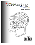
User Manual Edition Notes Edition Notes Trademarks Copyright Notice Manual Usage The COLORado™ Zoom Tour User Manual Rev. 07 covers the description, safety precautions, installation, programming, operation, and maintenance of the COLORado™ Zoom Tour. CHAUVET® released this edition of the COLORado™ Zoom Tour User Manual in August 2011. CHAUVET® is a registered trademark of CHAUVET & Sons Inc. (d/b/a CHAUVET® or Chauvet). The CHAUVET® logo in its entirety including the Chauvet name and the dotted triangle, and all other trademarks on this manual pertaining to services, products, or marketing statements (example: It’s Green Thinking™) are owned or licensed by CHAUVET®. Any other product names, logos, brands, company names, and other trademarks featured or referred to within this document are the property of their respective trademark holders. CHAUVET® owns the content of this user manual in its entirety, including but not limited to pictures, logos, trademarks, and resources. © Copyright 2011 CHAUVET®. All rights reserved. Electronically published by CHAUVET® in the United States of America. CHAUVET® authorizes its customers to download and print this manual for professional information purposes only. CHAUVET® expressly prohibits the usage, copy, storage, distribution, modification, or printing of this manual or its content for any other purpose without its written consent. Document Printing For better results, print this document in color, on letter size paper (8.5 x 11 inches), double sided. If using A4 paper (210 x 297 mm), configure your printer to scale the content accordingly. Intended Audience Any person in charge of installing, operating, and/or maintaining this product should read the guide that shipped with it as well as this manual in their entirety before installing, operating, or maintaining this product. Disclaimer Document Revision CHAUVET® believes that the information contained in this manual is accurate in all respects. However, CHAUVET® assumes no responsibility for any error or omissions in this document. CHAUVET® reserves the right to revise this document and to make changes from time to time in the content hereof without obligation of CHAUVET® to notify any person or company of such revision or changes. This does not constitute in any way a commitment by CHAUVET® to make such changes. CHAUVET® may issue a revision of this manual or a new edition of it to incorporate such changes. The COLORado™ Zoom Tour User Manual Rev. 07 supersedes all previous versions of this manual. Please discard any older versions of this manual you may have, whether in printed or electronic format, and replace them with this version. Author Date Editor Date D. Couppe 8/24/11 B. Pillow 8/29/11 COLORado™ Zoom Tour User Manual Rev. 07 Table of Contents Table of Contents 1. Before You Begin ................................................................................................ 1 What Is Included ................................................................................................................. 1 Unpacking Instructions ........................................................................................................ 1 Typographic Conventions ................................................................................................... 1 Icon Meaning....................................................................................................................... 1 Product at a Glance ............................................................................................................ 1 Safety Notes........................................................................................................................ 2 Expected LED Lifespan ...................................................................................................... 2 2. Introduction ......................................................................................................... 3 Product Description ............................................................................................................. 3 Features .............................................................................................................................. 3 Additional Features...................................................................................................................... 3 Product Overview ................................................................................................................ 4 Product Dimensions ............................................................................................................ 5 3. Setup .................................................................................................................... 6 AC Power ............................................................................................................................ 6 AC Plug ....................................................................................................................................... 6 Power Linking .............................................................................................................................. 6 DMX Linking ........................................................................................................................ 7 DMX Modes ................................................................................................................................. 7 Master/Slave Connectivity ........................................................................................................... 7 Mounting ............................................................................................................................. 8 Orientation ................................................................................................................................... 8 Rigging ........................................................................................................................................ 8 4. Operation ............................................................................................................. 9 Control Panel Description ................................................................................................... 9 Control Options ................................................................................................................... 9 Programming....................................................................................................................... 9 DMX Personality .......................................................................................................................... 9 DMX Control .............................................................................................................................. 10 Static Color ................................................................................................................................ 10 Auto Programs........................................................................................................................... 10 Edit Customs ............................................................................................................................. 10 Master/Slave.............................................................................................................................. 11 Color Settings ............................................................................................................................ 11 Dimmer Curves.......................................................................................................................... 11 Control Panel Lock .................................................................................................................... 12 Program Upload ........................................................................................................................ 12 Reset ......................................................................................................................................... 13 Whites Setting ........................................................................................................................... 13 White Calibration ....................................................................................................................... 13 TOUR Notes...................................................................................................................... 14 Master Dimmer .......................................................................................................................... 14 Red, Green, Blue and White Color Selection............................................................................ 14 Color Macros ............................................................................................................................. 14 Strobe ........................................................................................................................................ 14 Auto/Custom/Fan....................................................................................................................... 14 Dimmer Speed........................................................................................................................... 14 Zoom Selection.......................................................................................................................... 14 Zoom Reset ............................................................................................................................... 14 Menu Map ......................................................................................................................... 15 COLORado™ Zoom Tour User Manual Rev. 07 -i- Table of Contents DMX Values ...................................................................................................................... 16 Tour ........................................................................................................................................... 16 Tour (Cont.) ............................................................................................................................... 17 ARC1 ......................................................................................................................................... 17 ARC1 + D .................................................................................................................................. 17 ARC2 ......................................................................................................................................... 17 ARC2 + D .................................................................................................................................. 17 ARC2 + S .................................................................................................................................. 18 HSV ........................................................................................................................................... 18 5. Technical Information ....................................................................................... 19 Product Maintenance ........................................................................................................ 19 Troubleshooting Guide ...................................................................................................... 20 Returns Procedure ............................................................................................................ 21 Claims ............................................................................................................................... 21 Contact Us ........................................................................................................................ 21 Technical Specifications ................................................................................................... 22 -ii- COLORado™ Zoom Tour User Manual Rev. 07 Before You Begin 1. Before You Begin What Is Included One COLORado™ Zoom Tour One Gel Frame One NEUTRIK® powerCON® to Edison Plug Input Power Cord 5° Color Blending Filter One Safety Cable One Warranty Card One Quick Reference Guide Unpacking Instructions Immediately upon receiving this product, carefully unpack it and check the container in which you received it. Make sure that you have received all the parts indicated above and that they are all in good condition. If the material inside the container (this product and any other accessory included with it) appears damaged from shipping, or if the container shows signs of mishandling, notify the shipper immediately. In addition, retain the container and all the packing material for inspection. See the Claims section in the Technical Information chapter for more information. Typographic Conventions Convention 1~512 50/60 COLORado™ 1 <SET> Settings MENU > Settings 1~10 Yes/No ON Icon Meaning Icon Meaning A range of values in the text A set of mutually exclusive values in the text The name of another publication, manual, or section A button on the product’s control panel A product function or a menu option A sequence of menu options A range of menu values from which to choose in a menu A set of two mutually exclusive menu options in a menu A unique value to be entered or selected in a menu Meaning This icon indicates critical installation, configuration, or operation information. Failure to comply with this information may render the product partially or completely inoperative, damage third-party equipment, or cause harm to the user. This icon indicates important installation or configuration information. Failure to comply with this information may prevent the product from functioning correctly. This icon indicates useful, although non-critical information. The term “DMX” used throughout this document refers to the USITT DMX512-A transmission protocol. Product at a Glance Use on Dimmer Outdoor Use Sound Activated DMX Master/Slave COLORado™ Zoom Tour User Manual Rev. 07 Auto Programs Auto-ranging Power Supply Replaceable Fuse User Serviceable Duty Cycle -1- Before You Begin Safety Notes It is important to read all these notes before starting to work with this product. The Safety Notes include important safety information about the installation, usage, and maintenance of this product. There are no user serviceable parts inside this product. Any reference to servicing you may find from now on in this User Manual will only apply to properly CHAUVET® certified technicians. Do not open the housing or attempt any repairs unless you are certified to do so. Please refer to all applicable local codes and regulations for the proper installation of this product. Personal Safety Mounting and Rigging Power and Wiring Operation Avoid direct eye exposure to the light source while the product is on. Always disconnect this product from its power source before servicing. Always connect this product to a grounded circuit to avoid the risk of electrocution. Do not touch this product’s housing when operating because it may be very hot. This product is for indoor use only! To prevent risk of fire or shock, do not expose this product to rain or moisture. Make sure there are no flammable materials close to this product while operating. When hanging this product, always secure it to a fastening device using a safety cable (included). Always make sure that you are connecting this product to the proper voltage, as per the specifications in this manual or on the product’s sticker. Never connect this product to a dimmer pack or rheostat. Never disconnect this product by pulling or tugging on the power cable. Do not operate this product if you see damage on the housing, lenses, or cables. In any of these cases, have the damaged parts replaced by an authorized technician at once. Do not cover the ventilation slots when this product is operating to avoid internal overheating. The maximum ambient temperature (Ta) is 104° F (40° C). Do not operate this product at a higher temperature. In case of a serious operating problem, stop using this product immediately! In the unlikely event that your CHAUVET® product may require service, please contact CHAUVET® Technical Support. Expected LED Lifespan -2- LEDs gradually decline in brightness over time, mostly because of heat. Packaged in clusters, LEDs exhibit higher operating temperatures than in ideal, single LED conditions. For this reason, using clustered LEDs at their fullest intensity significantly reduces the LEDs’ lifespan. Under normal conditions, this lifespan can be of 40,000 to 50,000 hours. If extending this lifespan is vital, lower the operational temperature by improving the product’s ventilation and reducing the external temperature. In addition, limiting the overall projection intensity may also help to extend the LEDs’ lifespan. COLORado™ Zoom Tour User Manual Rev. 07 Introduction 2. Introduction Product Description Features Additional Features The COLORado™ Zoom Tour is a RGBW LED wash light. This product consists of a single module that houses the internal power supply, the control panel, the LED drivers, the LED boards, and motorized moving lenses, as well as the power and signal connectors. The COLORado™ Zoom Tour features a variable zoom, which enables the user to change the beam angle of the unit via DMX or control panel, and one mounting bracket that doubles as a floor mount and hanging support bracket. 3, 4, 5, 6, or 12-channel DMX control Operating modes: 3-channel: RGB 3-channel: HSV 4-channel: RGB, dimmer 4-channel: RGBW 5-channel: RGBW, dimmer 6-channel: RGBW, dimmer, strobe 12-channel: RGBW, dimmer, color macro, strobe, auto/custom programs, auto speed, dimmer speed, zoom, zoom reset Motorized Zoom RGBW static color mixing with or without DMX control Color temperature presets (3,200~10,000 K) Built-in automated programs Custom programs Recall auto or custom programs via control panel, DMX, or master/slave Color Calibration Five distinct dimming curves Additional power output: max 11 units @ 120 V, 22 units @ 208 V, 25 units @ 230 V NEUTRIK® PowerCon® power input and output connector 3 pin and 5 pin DMX input and output connectors LCD display with password protection COLORado™ Zoom Tour User Manual Rev. 07 -3- Introduction Product Overview Power in / power out Dmx in / DMX out Bottom View Double-bracket yoke Front View -4- COLORado™ Zoom Tour User Manual Rev. 07 Introduction Product Dimensions COLORado™ Zoom Tour User Manual Rev. 07 -5- Setup 3. Setup AC Power The COLORado™ Zoom Tour has an auto-ranging power supply that can work with an input voltage range of 100~240 VAC, 50/60 Hz. Make sure that you are connecting this product to the proper voltage, as per the specifications in this manual or on the product’s sticker. Always connect this product to a protected circuit with an appropriate electrical ground to avoid the risk of electrocution or fire. To determine the power requirements for the COLORado™ Zoom Tour, refer to the label affixed to the side of the product. Alternatively, you may refer to the Technical Specifications chart in the Technical Information chapter of this manual. The listed current rating indicates the maximum current draw during normal operation. For more information, you may download the Sizing the Circuit Breakers document from the CHAUVET® web site: www.chauvetpro.com Never connect this product to a rheostat (variable resistor) or dimmer circuit, even if the rheostat or dimmer channel serves only as a 0 to 100% switch. AC Plug Power Linking -6- The COLORado™ Zoom Tour comes with a power input cord terminated with a Neutrik® powerCON® A connector on one end and an Edison plug on the other end (US market). If the power input cord that came with your product has no plug or you need to change the Edison plug, use the table below to wire the new plug. Connection Wire (US) Wire (Europe) Screw Color AC Live Black Brown Yellow or Brass AC Neutral White Blue Silver AC Ground Green/Yellow Green/Yellow Green The COLORado™ Zoom Tour supports power linking for up to 11 other COLORado™ Zoom Tour units at 120 VAC. This product comes with a power input cord, but no power linking cord. However, a power linking cable is available as an option. COLORado™ Zoom Tour User Manual Rev. 07 Setup DMX Linking You may link the COLORado™ Zoom Tour to a DMX controller using a standard DMX serial connection. If using other DMX compatible units with this product, you can control them individually with a single DMX controller. If you are not familiar with the DMX standard, or if you need information about the DMX cables needed to link this product to a DMX controller, download the DMX Primer document from the CHAUVET® web site: www.chauvetpro.com. DMX Modes The COLORado™ Zoom Tour uses the standard DMX data connection for its TOUR, ARC1, AR1D, ARC2, AR2D, AR2S, and HSV DMX modes. You will find information about these DMX mode(s) in the Introduction chapter (brief description), the Operation chapter (configuration details), and the DMX Values section (individual channel values). Master/Slave Connectivity The Master/Slave mode allows a COLORado™ Zoom Tour (the “master unit”) to control one or more COLORado™ Zoom Tours (the “slave units”) without a DMX controller. A COLORado™ Zoom Tour becomes the master unit when running an Auto or Custom program, or by being in STATIC mode. You must configure the slave units to operate in “SLAVE” mode from their respective control panels. During the Master/Slave operation, the slave units will operate in unison with the master unit. DO NOT connect a DMX controller to the unit’s operating in Master/Slave mode. Otherwise, the signals from the DMX controller may interfere with the signals from the master unit. The Operation chapter of this manual provides detailed instructions on how to configure the Master and Slave units. COLORado™ Zoom Tour User Manual Rev. 07 -7- Setup Mounting Before mounting this product, read and follow the safety recommendations indicated in the Safety Notes section (page 2 of this manual). Orientation Always mount this product in a safe position making sure there is adequate room around it for ventilation, configuration, and maintenance. Rigging The COLORado™ Zoom Tour consists of the double-bracketed yoke and the body of the fixture. CHAUVET® recommends following the general guidelines below when mounting this product. When selecting an installation location, consider ease of access to this product for operation, programming adjustments, and routine maintenance. Make sure to mount this product away from any flammable material as indicated in the Safety Notes section. Never mount the product in places where rain, high humidity, extreme temperature changes, or restricted ventilation may affect it. If hanging this product, make sure that the location where you are mounting it can support its weight. Please refer to the Technical Specifications section of this manual for the weight requirement of this product. Procedure The COLORado™ Zoom Tour comes with a double-bracketed yoke to which you can attach mounting clamps or the yolk can serve as floor stand. You must supply your own mounting clamps. Make sure the clamps are capable of supporting the weight of this product. You will have to use at least one mounting point per unit. Clamp Safety Cable Product Mounting Diagram Doublebracketed yoke Overhead Mounting -8- Floor Mounting COLORado™ Zoom Tour User Manual Rev. 07 Operation 4. Operation Control Panel Description Control Options Programming DMX Personality Button Function <MENU> Exits from the current menu or function <ENTER> Enables the currently displayed menu or sets the currently selected value into the current function <UP> Navigates upward through the menu list and increases the numeric value when in a function <DOWN> Navigates downward through the menu list and decreases the numeric value when in a function You can set the COLORado™ Zoom Tour start address in the 001~512 DMX range. This allows for the control of up to 42 units in the 12-channel TOUR personality. Refer to the Menu Map on page 15 to learn how the menu options relate to each other. The Menu Map has a Main Level and a variable number of programming levels for each option. To go to an option in the Main Level, press <MENU> repeatedly until the option appears on the display. Press <ENTER> to select. You will go to the first programming level for that option. To select an option or value within the current programming level, press <UP> or <DOWN> until shown on the display. Press <ENTER> to select. If there is another programming level, you will see the level’s first option. If not, you will see the selected value. To exit to the previous menu level, press <MENU>. This setting allows the user to choose a particular DMX personality. 1. Go to PERS. 2. Select the desired personality (TOUR, ARC1, AR1D, ARC2, AR2D, AR2S, or HSV). See the DMX Values section for the highest starting address you can select for each personality. Make sure that the starting addresses on the various units do not overlap due to the new personality setting. See the DMX Values section. COLORado™ Zoom Tour User Manual Rev. 07 -9- Operation DMX Control In this mode, each unit will respond to a unique starting address from the DMX controller. All units with the same starting address will respond in unison. 1. Select a DMX personality as shown in DMX Personality. 2. Set the running mode: a. Go to RUN. b. Select DMX. 3. Set the starting address: a. Go to DMX. b. Select the starting address (001~512). The highest recommended starting address for each DMX mode is as follows: DMX Mode TOUR ARC1 AR1D Static Color Auto Programs DMX Address 501 510 509 DMX Mode ARC2 AR2D AR2S DMX Address 509 508 507 DMX Mode HSV DMX Address 510 The Static Color mode allows for permanent RGBW color mixing without a DMX controller. 1. Go to STAT. 2. Select the desired color (R., G., B., W., or Z.). 3. Select the desired color and zoom value (0~255). 4. Select (S.) 5. Select the desired frequency (0~20). Auto programs allow for dynamic RGBW color mixing without a DMX controller. 1. Go to AUTO. 2. Select the desired auto (AT. 01~10) or custom program (PR. 01~10). You cannot edit any of the auto programs (AT. 01~10). However, you can edit the custom programs (PR. 01~10). See Edit Customs for details. Edit Customs -10- This setting allows the programming of up to 30 scenes for each of the 10 customizable programs, including colors and effects. 1. Go to EDIT. 2. Select the desired custom program (PR. 01~10). 3. Select the desired scene (SC. 01~30). 4. Select the desired color or effect (R, G, B, W, Z, S, T, or F). 5. Select the color or effect value (000~255 for colors, zoom, and timers, or 00~20 for strobe). 6. Repeat for the other colors or effects. 7. Return to the scene level (step 3). 8. Repeat the settings of colors and effects for the other scenes. COLORado™ Zoom Tour User Manual Rev. 07 Operation Master/Slave The Master/Slave mode allows a group of COLORado™ Zoom Tours (the slave units) to simultaneously duplicate the output of another COLORado™ Zoom Tour (the master unit) without a DMX controller. 1. Set each of the slave units: a. Go to RUN. b. Select SLAV. 2. Set the master unit: a. Set the running mode to DMX as explained in DMX Control. b. Select an auto or custom program as explained in Auto Programs, or a static mix of colors. The master unit is the one that runs a program, whether Auto, Custom, or Static mode. Do not connect a DMX controller to the units configured for Master/Slave operation. The master unit should be the first in the DMX string. Color Settings The COLOR setting determines how the COLORado™ Zoom Tour generates the white color based on various RGB settings. 1. Go to SET. 2. Select COLO. 3. Select OFF, RGBW, or UC. OFF: When the RGB faders are all set to 255, the output is maximum, although the resulting white color may not be balanced. RGBW: When the RGB faders are all set to 255, the resulting output is defined by the configured white color (see White s Settings). UC: When the RGB faders are all set to 255, the output matches that of less efficient products (Universal Color). Dimmer Curves This setting determines how fast the output of the COLORado™ Zoom Tour changes when the operator modifies the values of the Red, Green, Blue, White, and Dimmer faders. This setting gives the user four different options to simulate the dimming curve of an incandescent lighting product. 1. Go to SET. 2. Select DIM. 3. Select a dimmer curve (OFF, DIM1, DIM2, DIM3, or DIM4). OFF: The output is proportional (linear) to the Dimmer and RGBW channel values. DIM1~4: The output follows the Dimmer and RGBW channel values based on the corresponding dimmer curve. DIM1 is the fastest and DIM4 is the slowest. COLORado™ Zoom Tour User Manual Rev. 07 -11- Operation Control Panel Lock This setting allows the user to activate or disable the control panel lock, which keeps nonauthorized personnel from changing the product’s settings. 1. Go to KEY. 2. Select ON or OFF. When the control panel lock is active, the product will prompt the user to enter the password after 30 seconds of control panel inactivity or after turning on the product. After being prompted to enter the password: Press <UP>, <DOWN>, <UP>, <DOWN>, and <ENTER>. Program Upload This option allows the user to copy the custom programs of one COLORado™ Zoom Tour unit onto other COLORado™ Zoom Tour units by using the Master/Slave method. 1. Configure and connect the units in a Master/Slave arrangement, where the master unit has the custom programs you want to transfer to the slave units. 2. At the master unit, go to SET. 3. Select UPLD. 4. When PASS shows, press <ENTER>. 5. Enter the master access password as shown in Control Panel Lock. 6. When SEND shows, press <ENTER> to start the upload. 7. Wait for the upload process to finish (the display will show END/MAIN) before continuing or turning the units off. The master and slave units will light up to provide the status of the process, as follows: Yellow indicates that the upload process is running. Green indicates that the upload process completed successfully. Red indicates that the upload process failed due to an error. Recheck all cable connections and restart the process. If the issue persists, contact Chauvet Technical Support. DO NOT upload the program from a COLORado™ Zoom Tour to a different product. You could render the other unit inoperative. -12- COLORado™ Zoom Tour User Manual Rev. 07 Operation Reset Default Values Whites Setting White Calibration This setting allows the user to reset the COLORado™ Zoom Tour to its default values, including the custom programs. 1. Go to SET. 2. Select REST. 3. When PASS shows, press <ENTER>. 4. Enter the master access password as shown in Control Panel Lock. 5. Wait for the reset process to finish. Parameter STAT AUTO ADDR RUN PERS DIM Default Value R/G/B.000 AT.01 D.001 DMX TOUR DIM4 Parameter COLO EDIT CAL1 CAL2 KEY Default Value UC PR.01/SC.01 WH.01 R/G/B.255 OFF This setting allows the user to select and edit the temperature of the white colors used in channel 6 (Macros) when in the TOUR mode. It also allows the user to define the maximum RGB values when RGB to White (RGB.W) is active. 1. Go to CAL1. 2. Select a white color (WH. 1~11). 3. Select a color (R., G., B., or W.). 4. Select a color value (0~255). 5. Repeat for the other colors. This setting allows the user to select the white color shown by the COLORado™ Zoom Tour when the color setting is RGBW and the DMX controller’s Red, Green, and Blue faders are set to 255. 1. Go to CAL2. 2. Select a color (R., G., or B.). 3. Select a color value (0~255). 4. Repeat for the other colors When selecting CAL2 > RGBW you will only be able to define the values of R. (red), G. (green), and B. (blue). The values of R. (red), G. (green), and B. (blue) configured from CAL2 > RGBW will define the color temperature shown when the RGB faders are set to 255 if SET > COLO > RGBW is active. COLORado™ Zoom Tour User Manual Rev. 07 -13- Operation TOUR Notes Master Dimmer Red, Green, Blue and White Color Selection Color Macros These notes intend to clarify the way the TOUR DMX personality works. Channel 1 controls the intensity of the currently projected color. When the slider is at the highest position (100%), the intensity of the output is at its maximum. Channels 2 through 5 control the intensity ratio of each of the Red, Green, Blue, and White LEDs. When the slider is at the highest position (100%), the intensity of each color is at its maximum if SET > COLO is OFF. You can combine channels 2 through 5 to create over one trillion colors. Channel 6 selects the required Color Macro. Channel 6 has priority over channels 2 through 5. Channel 1 controls the intensity of the Color Macro. Strobe Channel 7 controls the strobe frequency (not the intensity) of channels 2 through 6. Channel 7 can strobe channels 2 through 7 when not running macros, allowing the individual faders (RGB and W) as well as channel 1 (D) to control the output intensity. Channel 7 can strobe channel 6 when running macros, allowing channel 6 to select the macro and channel 1 to control the output intensity. Auto/Custom/Fan Channel 8 selects the preset auto programs AT. 01~10 or the custom programs PR. 01~10. When activating the custom Auto programs PR. 01~10, it is possible to control the Step Time and Fade Time using channels 2 and 3 respectively. Channel 9 has priority over channels 2 through 7. Channel 9 controls the speed at which each auto programs plays. Dimmer Speed Zoom Selection Zoom Reset -14- Channel 10 selects the dimmer mode and speed. When DIMMER is set to OFF, the changes in the RGBW and Master Dimmer faders are linear. Otherwise, DIM1 is the fastest dimmer curve, while DIM4 is the slowest. Channel 11 controls the zoom function. Channel 12 resets the zoom function to the starting position. COLORado™ Zoom Tour User Manual Rev. 07 Operation Menu Map Main Level STATIC AUTO Programming Levels R. G. B. W. Z. S. AT. PR. DMX Description 000~255 0~20 1~10 001~512 DMX SLAV RUN TOUR PERS UPLOAD REST DIM SET ARC1 AR1.D ARC.2 AR2.D AR2.S HSV Enter password Enter password OFF DIM1~4 BLAK DERR COLR EDIT CALIB1 CALIB2 KEY R. G. B. PR. SC. W. (01~10) (01~30) Z. S. T. F. R. G. WH 1~11 B. W. R. RGBW G. B. ON/OFF COLORado™ Zoom Tour User Manual Rev. 07 SAVE OFF RGBW UC 000~255 0~20 Combines Red, Green, Blue, and White to generate a custom color (0~100%) Changes the beam angle Strobe frequency (0~20 Hz) Choose from 10 automatic programs Choose from 10 customizable programs Sets the DMX starting address Receives signals from DMX controller Receives signals from Master unit 12-channel: RGBWA, D, A/C, AS, DS, Macro, S, Z, ZR 3 channel: RGB 4-channel: RGB, D 4-channel: RGBW 5-channel: RGBW, D 6-channel: RGBW, D, S 3 channel: HSV Transfers custom programs Defaults fixture No dimmer Dimmer curve All LED’s turn off when DMX signal is lost All LED’s stay on the last command used when the DMX signal is lost. RGB set to “255”= max. output RGB set to “255” = balanced white Universal color balance Combines Red, Green, Blue, White, and Zoom, as well as strobe and timers to create the scenes of a custom program 000~255 000~255 Modifies the color macros used in channel 6 of the TOUR personality 000~255 Defines the color temperature used when COLOR is set to RGB to W. Turns the password on or off -15- Operation DMX Values Tour Channel Function Value Percent/Setting Dimmer Red Step Time Green Step Time 000 255 4 Blue 000 255 0~100% 0~100% When CUS. 01-10 in CH. 8 is activated 0~100% When CUS. 01-10 in CH. 8 is activated 0~100% 5 White 000 255 0~100% 6 Color Macro + White Balance 000 010 011 030 031 050 051 070 071 090 091 110 111 130 131 150 151 170 171 200 201 205 206 210 211 215 216 220 221 225 226 230 231 235 236 240 241 245 246 250 250 255 No Function R: 100% G: Up R: Down G: 100% R: 0% G: 100% R: 0% G: Down R: Up G: 0% R: 100% G: 0% R: 100% G: Up R: Down G: Down R: Down G: Down White 1: 3,200 K White 2: 3,400 K White 3: 4,200 K White 4: 4,900 K White 5: 5,600 K White 6: 5,900 K White 7: 6,500 K White 8: 7,200 K White 9: 8,000 K White 10: 8,500 K White 10: 10,000 K 7 Strobe 000 010 011 255 No Function 0~20 Hz Auto + Custom Programs 000 020 021 030 031 040 041 050 051 060 061 070 071 080 081 090 091 100 101 110 111 120 121 130 131 140 141 150 151 160 161 170 171 180 181 190 No function Auto 1 Auto 2 Auto 3 Auto 4 Auto 5 Auto 6 Auto 7 Auto 8 Auto 9 Auto 10 Custom 1 Custom 2 Custom 3 Custom 4 Custom 5 Custom 6 Custom 7 1 2 3 8 000 255 000 255 B: 0% B: 0% B: Up B: 100% B: 100% B: Down B: Up B: 100% B: 100% W: 100% Continues on the next page -16- COLORado™ Zoom Tour User Manual Rev. 07 Operation Continued from previous page Tour (Cont.) Channel Function 191 200 201 210 211 220 221 255 Custom 8 Custom 9 Custom 10 No function Auto Speed 000 255 Only when CH. 8 is 021~120 10 Dimmer Speed 000 009 010 029 030 069 070 129 130 189 190 255 Dimmer speed as per Control Panel Linear dimmer Non-linear dimmer 1 (fastest) Non-linear dimmer 2 Non-linear dimmer 3 Non-linear dimmer 4 (slowest) 11 Zoom 000 255 0~100% 12 Zoom Reset 000 200 201 220 221 255 No function Zoom reset No function 9 ARC1 + D ARC2 ARC2 + D Percent/Setting Auto + Custom Programs 8 (Cont.) ARC1 Value Channel Function Value Percent/Setting 1 Red 000 255 0~100% 2 Green 000 255 0~100% 3 Blue 000 255 0~100% Channel Function Value Percent/Setting 1 Master Dimmer 000 255 0~100% 2 Red 000 255 0~100% 3 Green 000 255 0~100% 4 Blue 000 255 0~100% Channel Function Value Percent/Setting 1 Red 000 255 0~100% 2 Green 000 255 0~100% 3 Blue 000 255 0~100% 4 White 000 255 0~100% Channel Function Value Percent/Setting 1 Master Dimmer 000 255 0~100% 2 Red 000 255 0~100% 3 Green 000 255 0~100% 4 Blue 000 255 0~100% 5 White 000 255 0~100% Continues on the next page COLORado™ Zoom Tour User Manual Rev. 07 -17- Operation Continued from previous page ARC2 + S Channel HSV Value Percent/Setting 000 255 0~100% 2 Red 000 255 0~100% 3 Green 000 255 0~100% 4 Blue 000 255 0~100% 5 White 000 255 0~100% 6 Strobe 000 009 010 255 No Function 0~20 Hz Channel 1 -18- Function Master Dimmer 1 Function Hue Value 000 255 Percent/Setting 0~100% 2 Saturation 000 255 0~100% 3 Value 000 255 0~100% COLORado™ Zoom Tour User Manual Rev. 07 Technical Information 5. Technical Information Product Maintenance To maintain optimum performance and minimize wear, the user should clean this product frequently. Usage and environment are contributing factors in determining the cleaning frequency. As a rule, the user should clean this product at least twice a month. Dust build up reduces light output performance and can cause overheating. This can lead to reduced light source life and increased mechanical wear. To clean a COLORado™ Zoom Tour, follow the recommendations below: Unplug the unit from power. Wait until the unit is cool. Use a vacuum (or dry compressed air) and a soft brush to remove dust collected on the external vents and accessible internal components. Clean all external glass surfaces with a mild solution of non-ammonia glass cleaner or isopropyl alcohol. Apply the solution directly to a soft, lint-free cotton cloth or a lens cleaning tissue. Drag any dirt or grime to the outside of the glass surface. Gently polish the glass surfaces until they are free of haze and lint. Always dry the external glass surfaces carefully after cleaning them. COLORado™ Zoom Tour User Manual Rev. 07 -19- Technical Information Troubleshooting Guide Symptom Fixture does not light up The wrong LEDs light up when using DMX The wrong LEDs light up when using DMX Circuit breaker/fuse keeps tripping/blowing Unit does not power up Unit does not respond to wired DMX or responds erratically Cause(s) Action(s) Dimmer fader set to “0” All color faders set to “0” All colors in STATIC are set to “0” No power Faulty internal power supply Faulty main control board Increase the value of the dimmer channel Increase the value of the color channels Increase the values of the colors Verify external power circuit and wiring Wrong personality Change the personality Wrong DMX address Change the DMX address Wrong personality Change the personality Wrong DMX address Change the DMX address Excessive circuit load Short circuit along the power wires No power Loose or damaged power cord Faulty internal power supply Wrong DMX addressing Damaged DMX cables Wrong polarity on the controller Loose DMX cables Non DMX cables Bouncing signals Long cable / low level signal Reduce total load placed on the electrical circuit Check electrical wiring Check for voltage on outlet Check power cord Send unit for repair Check unit addressing Check DMX cables Check polarity switch settings on the controller Check cable connections Use only DMX compatible cables Install terminator as suggested Install an optically coupled DMX splitter before a long section of cable or right after the unit with the strong signal Install an optically coupled DMX splitter after unit #32 Keep DMX cables separated from power cables or fluorescent/black lights Send unit for repair Too many units Interference from AC wires Faulty Display/Main/DMX interface board Send unit for repair If you still experience technical problems after trying the above solutions or if you need to send the unit for repair, contact CHAUVET® Technical Support. -20- COLORado™ Zoom Tour User Manual Rev. 07 Technical Information Returns Procedure The user must send the merchandise prepaid, in the original box, and with its original packing and accessories. CHAUVET® will not issue call tags. Call CHAUVET® and request a Return Merchandise Authorization (RMA) number before shipping the product. Be prepared to provide the model number, serial number, and a brief description of the cause for the return. The user must clearly label the package with a Return Merchandise Authorization (RMA) number. CHAUVET® will refuse any product returned without an RMA number. DO NOT write the RMA number directly on the box. Instead, write it on a properly affixed label. Once you have received the RMA number please include the following information on a piece of paper inside the box: Your name Your address Your phone number The RMA number A brief description of the problem Be sure to pack the product properly. Any shipping damage resulting from inadequate packaging will be the customer’s responsibility. As a suggestion, proper FedEx packing or double boxing is the method Chauvet® recommends. CHAUVET® reserves the right to use its own discretion to repair or replace returned product(s). Claims Contact Us The carrier is responsible for any damage incurred during shipping to this product or any part that shipped with it. Therefore, if the received merchandise appears to have damages caused during shipping, the customer must submit the damage report and any related claims with the carrier, not CHAUVET®. The customer must submit the report upon reception of the damaged merchandise. Failure to do so in a timely manner may invalidate the customer’s claim with the carrier. For other issues such as missing components or parts, damage not related to shipping, or concealed damage, the customer must make claims to CHAUVET® within seven (7) days of receiving the merchandise. World Headquarters United Kingdom & Ireland CHAUVET® CHAUVET® Europe Ltd. General Information Address: Voice: Fax: Toll free: General Information 5200 NW 108th Avenue Sunrise, FL 33351 (954) 929-1115 (954) 929-5560 (800) 762-1084 (954) 929-1115 (Press 4) (954) 756-8015 [email protected] Email: [email protected] World Wide Web World Wide Web www.chauvetpro.com COLORado™ Zoom Tour User Manual Rev. 07 Voice: Fax: Unit 1C Brookhill Road Industrial Estate Pinxton, Nottingham, UK NG16 6NT +44 (0)1773 511115 +44 (0)1773 511110 Technical Support Technical Support Voice: Fax: Email: Address: www.chauvetlighting.co.uk -21- Technical Information Technical Specifications Dimensions and Weight Length Width Height Weight 8.0 in (203 mm) 9.8 in (250 mm) 13.1 in (334 mm) 14.5 lbs (6.6 kg) Note: Dimensions in inches rounded to the nearest decimal digit. Electrical Light Source Photo Optic Thermal DMX Ordering -22- Power Supply Type Range Voltage Selection Switching (internal) 100~240 V, 50/60 Hz Auto-ranging Parameter 120 V, 60 Hz 230 V, 50 Hz Consumption Operating current Power linking units Fuse/Breaker 126 W 1.2 A 11 N/A 122 W .54 A 25 N/A Power I/O US/Worldwide Europe Power input connector Power output connector Power cord plug Neutrik® powerCON® A Neutrik® powerCON® B Edison (US) Neutrik® powerCON® A Neutrik® powerCON® B Local plug Type Power Current Lifespan LED 2&3W 804 mA 50,000 hours Color Quantity Red Green Blue White 10 10 10 7 Parameter Illuminance @ 5 m Beam angle Field angle 3520 lx 8~30º 12~44º Max. External Temperature Cooling System 104° F (40° C) Convection I/O Connectors Connector Type Channel Range 3- and 5-pin XLR Sockets 3, 4, 5, 6, 12 Product Name Item Code Item Number COLORado™ Zoom Tour 01030306 COLORADOZOOMTOUR COLORado™ Zoom Tour User Manual Rev. 07 CHAUVET® 5200 NW 108th Avenue Sunrise, FL 33351 (USA) (800) 762-1084 – (954) 929-1115 FAX (954) 929-5560 www.chauvetlighting.com. COLORado™ Zoom Tour User Manual Rev. 07 August 2011