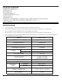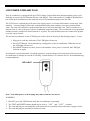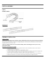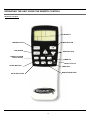
1
Portable Air Conditioner with
Heat Pump Technology
Operating Instructions
3092402
Model No.: HCB-P13HP-D
Reference No.: BPD13HP
V140217
Thank you for choosing a Soleus Air Portable Air Conditioner with Heat Pump Technology. This
owner’s manual will provide you with valuable information necessary for the proper care and
maintenance of your new product. Please take a few moments to thoroughly read the instructions and
familiarize yourself with all the operational aspects of your new Soleus Air Portable Air Conditioner
with Heat Pump technology.
For your own records, please attach a copy of your sales receipt to this manual. Also, write the store
name/location, date purchased, and serial number below:
Store Name: ____________________________________________________
Location: ______________________________________________________
Date Purchased: _________________________________________________
Serial Number (located on back of unit): ______________________________
IMPORTANT INSTRUCTIONS
Before installing and using your portable air conditioner, please read this owner’s manual carefully. Store this
manual in a safe place for future reference.
1) Always place the unit on a level surface.
2) Never use or store gasoline or other flammable vapor or liquid near this unit unless instructed by this manual.
3) Maintain at least 10 inches (25 cm) clearance space around this unit. Do not block or cover air inlet or outlet grilles.
4) The unit must be connected to a correctly grounded power supply.
5) Do not start or stop the unit by inserting or pulling out the power plug.
6) Do not use an adapter plug or extension cord.
7) Do not use the unit in the immediate surroundings of a bath, a shower or a swimming pool.
8) Do not insert anything into the air outlet. Do not obstruct air inlet or outlet grills unless instructed by this manual.
9) Do not let children play near this unit.
10) Always inspect the cord for signs of damage before use. If the power cord is damaged, it must be replaced by the
manufacturer or a qualified service technician.
11) When cleaning the unit, always turn the unit off and unplug the power cord.
12) When the unit is not in use, always remove the venting kit from window.
13) Do Not Mix Old And New Batteries. Do Not Mix Alkaline, Standard (Carbon - Zinc), Or Rechargeable (Nickel Cadmium) Batteries.
14) When changing between heating and cooling mode there will be a 3-5 minute delay for the compressor to start.
During this time, the refrigerant inside the portable air conditioner will return to the compressor to start heating or
cooling your area.
2
PACKAGE CONTENTS
Portable Air Conditioner (1)
Exhaust Hoses (2)
Hose Adapters (2)
Window Kit Adapter (2)
Air Intake and Outlet Covers (2)
Remote Control (1)
AAA Batteries (2)
Window Kit - 4 Sliding Panels (1 dual hose panel, 1 single hose panel, 2 extension panels)
Air Intake Vent for Single Hose Installation (Additional Accessory) (1)
Owner’s Manual (1)
SPECIFICATIONS
•
The cooling capacity is measured at an ambient temperature of DB 86 °F, WB 78 °F.
•
Noise level is measured at a distance of 3.28 ft away from the front of the unit, when the unit is in cooling mode.
•
Power consumption is measured when the fan runs at the highest speed setting.
•
These specifications are for reference only. For actual data, please refer to the rating label on the back of the unit.
•
If the environment temperature is higher than the max operating temperature or lower than the minimum operating temperature,
the air conditioner may not work properly.
MODEL
HCB-P13HP-D
REFERENCE NUMBER
BPD13HP
COOLING CAPACITY
13,000 BTU/H
HEATING CAPACITY
12,500 BTU/H
DEHUMIDIFIER CAPACITY
60 pts/Day
POWER
COOLING
1390W
HEATING
1180W
AIR FLOW VOLUME
225 CFM
POWER SOURCE
115 V~ 60 HZ
11 AMP / 12.5 AMP
HEATING / COOLING
SOUND PRESSURE LEVEL
50 dB(A) at the lowest fan speed
NET WEIGHT
88 Lbs
OPERATING
TEMP
COOLING
60.8℉-107.6℉
HEATING
23℉-89.6℉
PRODUCT DIMENSIONS
19” W ×18.5” D ×32.25” H
REFRIGERANT
R-410A
3
LCDI POWER CORD AND PLUG
This air conditioner is equipped with an LCDI (Leakage Current Detection and Interruption) power cord
and plug as required by US National Electric Code 440.65. This cord consists of a length of shielded flexible cord with no termination on the load side and a LCDI attachment plug on the line side.
The LCDI power cord and plug will remove the supply source via electrical disconnect (circuit trip) if the
nominal current leakage between the cord shield and either load conductor exceeds a predetermined
value. The cord will remain de-energized until the devise has been manually reset. This is intended to reduce the risk of a fire in the power cord or combustible materials nearby. The cord shields are not grounded
and they must be considered a shock hazards if exposed. The cord shield must not be connected to ground
or to any exposed metal.
The test and reset buttons on the LCDI Plug are used to check if the plug is functioning properly. To test:
1. Plug power cord into wall outlet. The LED light will turn on.
2. Press TEST Button, circuit should trip, cutting power to the air conditioner. When this occurs,
the LED light will turn off.
3. Press RESET button to restore power to the machine. Once power is restored, the LED light
will turn on again.
If test button is pressed and unit can still be turned on, current leakage has been detected. Do not use the
air conditioner or attempt to reset the LCDI Plug. Contact Soleus Air Customer Service for troubleshooting
recommendations.
LED LIGHT
Note: Your units power cord and plug may differ from the one shown.
WARNING:
1.
2.
3.
4.
DO NOT press the TEST button while the air conditioner is operating.
The TEST and RESET buttons should not be used as “ON” and “OFF” switches.
The cord and plug are not intended to offer protection to externally connected loads or supply circuits.
The cord and plug are intended for indoor use only.
4
PARTS & ASSEMBLY
PARTS
EXHAUST HOSES
WINDOW KIT
ASSEMBLY & INSTALLATION
INSTALLATION
When the unit is operating as an air conditioner, heater, or dehumidifier, the unit draws in fresh outdoor air and exhausts
hot air (in AC or dehumidifier mode) or cool air (in Heat mode) out of the room to complete the air exchange. When the
unit is operating in fan mode, no outdoor air exchange takes place. The window kit and exhaust hose do not need to be
installed when the unit is used as a fan.
NOTE: The supplied window kit can be installed in sliding windows and sliding glass doors up to 8 ft. long
(approximate length).
MOUNTING THE EXHAUST HOSES
• Choose a suitable location, near a grounded electrical outlet and suitable window or door. Remove
packaging and locate components.
• Extend both ends of the exhaust hoses approximately 6 inches.
• Screw the window kit adapter onto one end of the exhaust hose clockwise. Screw the hose adapter onto
the other end of the exhaust hose clockwise. Repeat on the other exhaust hose.
• Remove outlet covers from the back of the unit by screwing them counter-clockwise, then lifting up.
• Mount the exhaust hoses onto the back of the unit by locking the hose adapters into place.
5
DUAL HOSE WINDOW KIT INSTALLATION - To quickly and efficiently cool a large area.
NOTE: The air conditioner in the images below may differ from the air conditioner you purchased. These
images are for your reference and show how to connect any Soleus Air dual hose air conditioner.
When using to a sliding door, it is recommend to make
the air outlet up to air inlet.
6
WINDOW KIT ASSEMBLY
1.Parts:
A) 2 Track Screws
B) 2 Wing Nuts
C1 & C2) 2 Hose Panels, one with Two Exhaust Hose Openings
D) 1 Sliding Track Panel
5. Next, take the other Hose Panel (C2) and connect it
to Hose Panel (C1) by placing the Sliding Track
Panel (D) over the Track Screw (A) on Hose Panel
(C2).
2. Assembly:
First, take the Track Screws (A) and screw one into
each of the small holes found on the Hose Panels
(C1 & C2).
6. The Hose Panels (C1 &C2) should now be
connected using the Sliding Track Panel (D).
3. Next, take the Wing Nuts (B) and tighten them
around each of the Track Screws (A). Do not tighten
the Wing Nuts (B) all the way; make sure they are
somewhat loose.
7. To complete the assembly, tighten the wing Nuts
(B) installed earlier. The finished Window Kit should
resemble the image seen below.
4. Now, place the Sliding Track Panel (D) over
the Track Screw (A) on Hose Panel (C1).
7
SINGLE HOSE EXHAUST & WINDOW KIT INSTALLATION
When you want quick spot cooling, install the PH4-13R-01 using the single hose window kit installation.
For Single Hose Installation
Install only the left exhaust hose over the circular air outlet (this outlet will be on the left side of the unit when
you are facing the back of the unit). Cover the right circular air intake using the exhaust intake cover. After
installing the hose remove the square air intake cover on the back of the unit and install the square air intake
vent with removable/washable filter.
Exhaust Hose installed
onto circular air outlet
on left side
Exhaust cover installed
over circular air intake on
right side
Air Intake Vent*
Air Intake Cover
*Additional Accessory
For Single Hose Window Kit Installation
To install the window kit, follow the same directions on page 6 for dual hose installation, but instead of using
the dual hose window kit panel, use the single hose panel pictured below.
Single Hose Window Kit Panel
8
CONTROL PANEL, DISPLAY, & OPERATING INSTRUCTIONS
CONTROL PANEL & MULTI-COLOR DISPLAY
TEMP & TIMER SELECTION
CONTROL PANEL
FAN SPEED BUTTON
SWING BUTTON
POWER BUTTON
TIMER BUTTONS
MODE BUTTON
TEMP SELECT
MULTI-COLOR DISPLAY
AUTO
A/C
DEHUM.
FAN
FAN SPEED
HEAT
TEMPERATURE
AND TIMER
INDICATOR
OSCILLATION ON/OFF
SLEEP MODE
ON/OFF
BUCKET FULL
TIMER ON
TIMER OFF
COMPRESSOR ON/OFF
9
OPERATING INSTRUCTIONS
CONTROL PANEL BUTTONS (Refer to the images on page 9)
1) Power On and Off - Press the POWER button once to manually turn the unit on. Press the POWER
button once more to turn the unit off.
2) Mode Selection - Press the MODE Button repeatedly to cycle between the different modes: Auto mode,
Air Conditioner, Dehumidifier, Fan only, and Heater.
3) Fan Speed Control - Press the FAN SPEED Button to cycle through the different fan speeds: High,
Medium, and low. The fan speed can be visually distinguished by the speed of the fan icon on the front
panel. There is an additional auto speed setting that is enabled in only heating and cooling modes. This
speed is next setting after low when pressing the speed control button. The speeds will cycle through in this
order: High, Medium, Low, Auto. Each change in speed will be associated with a “beep” sound from the
unit.
4) Temperature - Select the desired temperature by pressing either ▼ or ▲ key when using the unit in
cooling or heating mode. The temperature indicator flashes to display the desired temperature setting. After
the temperature is set, the unit will display this temperature setting until it is changed by the user. The
Multi-color display shows temperature in Celsius or Fahrenheit. Pressing the ▼and ▲ buttons
simultaneously will change the temperature select between °F and °C.
5) Timer - To program the timer, press the TIMER ON button until the display shows a flashing “
”.
Press the ▲ or ▼ buttons to change the clock to the desired time for the unit to automatically turn on.
Press the TIMER OFF button and the display on the unit will flash “
”. Press the ▲ or ▼
buttons to change the clock to the desired time for the unit to automatically turn off. The TIMER OFF
indicator will flash for 3 seconds to activate the times you programmed.
NOTE: The timer will also remember your settings when it is set. If you set the timer while in Air
Conditioning mode, the timer will automatically turn the unit on and off in air conditioning mode according to
the desired programmed times. The timer will also remember the temperature settings, fan speed, and
oscillation setting. The timer works when the unit is in Air Conditioner mode, Heating mode, Dehumidifier
mode, Fan mode, and Auto mode
OPERATING THE UNIT USING THE CONTROL PANEL
Air Conditioner Mode
1) Install the exhaust hoses and window kit properly (see pages 6,7 & 8).
2) Plug the Power Cord into an electrical outlet.
3) Turn on the unit by pressing the POWER button on the control panel.
4) Press the Mode button until the “
” icon appears on the Multi-color display
5) Press the ▲ or ▼ buttons until the desired room temperature appears on the control panel
°
°
°
°
display. The temperature ranges from 61 F - 88 F (16 C - 31 C).
6) Select the desired fan speed by pressing the FAN SPEED button.
10
NOTE: During hot days, the unit will cool the room most efficiently by setting the temperature at the lowest
setting and the fan speed on high. Reducing the length of the exhaust duct, insulating the exhaust hose and
window kit, and keeping direct sunlight to a minimum will also improve the cooling efficiency.
NOTE: When the unit is running on cooling mode, the exhaust hoses are required and must be
vented outside using the supplied window kit.
Dehumidifier Mode
1) Install the exhaust hoses and window kit properly (see pages 6,7 & 8).
2) Plug the Power Cord into an electrical outlet.
3) Turn on the unit by pressing the POWER Button on the control panel.
4) Press the MODE button until the “
” appears on the control panel display.
NOTE: The unit operates at low fan speed during dehumidifier mode. The unit cools room slightly during
the dehumidification. Keep the windows and doors closed to aid the effectiveness of the unit in removing the
moisture from the room.
NOTE: When the unit is running on dehumidifier mode, the exhaust hoses are required and must
be vented outside using the supplied window kit.
°
NOTE: The unit will not perform in dehumidifier mode when the room temperature is lower than 61 F .
Fan Mode
1) Plug the Power Cord into an electrical outlet.
2) Turn on the unit by pressing the POWER button on the control panel.
3) Press the MODE button until the “
” icon appears on the control panel display.
4) Select the fan speed by pressing the FAN SPEED button.
5) To circulate more air, press the SWING button on the remote control. The louvers will oscillate which
moves the louvers up and down to increase air circulation.
NOTE: It is not necessary for the exhaust hoses and window kit to be installed to operate the unit in fan mode.
Heating Mode
1) Install the exhaust hoses and window kit properly (see pages 6,7 & 8).
2) Plug the Power Cord into an electrical outlet.
3) Turn on the unit by pressing the POWER button on the control panel.
4) Press the MODE button until the “
“ icon appears on the control panel display.
5) Press the ▼or ▲ buttons until the desired room temperature appears on the control panel display. The
°
°
°
°
temperature ranges from 61 F - 88 F (16 C - 31 C).
6) Select the fan speed by pressing the FAN SPEED button. It is recommended to set the fan speed to low.
NOTE: When heat mode is selected, the unit will shut down for 3-5 minutes, then start in heating mode.
NOTE: When the unit is running on heating mode, the exhaust hoses are required and must be
vented outside using the supplied window kit.
11
Auto Mode
1) Install the exhaust hoses and window kit properly (see pages 6,7 & 8).
2) Plug the Power Cord into an electrical outlet.
3) Turn on the unit by pressing the POWER button on the control panel.
4) Press the MODE button until the “
by pressing the FAN SPEED button.
” icon appears on the control panel display. Select the fan speed
°
NOTE: During AUTO mode, the unit operates in Heating mode when the room temperature is below 68 F,
°
°
Dehumidifier mode when the room temperature is between 68 F to 80 F. And Air Conditioner mode when
°
the room temperature is above 80 F.
Sleep Mode (This mode can only be selected when using the Remote control )
1) To set Sleep mode, make sure the unit is in Air Conditioner mode or Heating mode.
2) Press the SLEEP Button on the remote control. The “
” icon appears on the control panel display.
3) When in SLEEP mode, the fan will run on low to keep fan noise at a minimum.
°
4) When in Air Conditioner mode, the temperature setting will gradually increase to 2 F above the original set
temperature for 6 hours. After 6 hours the temperature setting will return to the set temperature.
°
5) When in Heating mode, the temperature setting will gradually decrease to 2 F below the original set
temperature for 6 hours. After 6 hours, the temperature setting will return to the set temperature.
6) When in Dehumidifier mode, the temperature will not change when Sleep mode is selected.
Compressor Indicator
The “
” icon will light up on the control panel display when the compressor turns on. The “
turn off when the compressor shuts off.
12
” icon will
Emergency Condensate Holding Tank
When the room temperature is low and the indoor humidity is high, the air conditioner may not be able to
evaporate some of the moisture fast enough. When this happens, the water will accumulate in an emergency
condensate tank inside the unit. Once the emergency condensate tank is full, the unit will automatically shut
off and the “
” will appear on the control panel display. To empty the condensate tank, unscrew the screw
plug at the bottom back of the unit. You will need a small pan, approximately 1” high to catch the water
coming out of the condensate tank. Once the condensate tank is drained, the unit will begin working within a
few minutes. The emergency condensate tank holds approximately 1.5 Liters of water. Another option is to
purchase a small hose from a hardware store that can fit around the 5/8” drain plug on the back of the unit and
drain the unit into a gravity drain or larger pan for continuous drainage.
To resume operation quickly, empty the water container according to the following steps:
1. Turn the unit off. Do not move the unit when the water container is full.
2. Place the drain pan accessory under the drainage port at the back of the unit.
3. Remove the screw plug from the drain hole. The condensate water will drain out automatically. When the
drain pan is full, screw the screw plug back onto the drainage hole to stop the water flow. Empty the drain
pan. Repeat until all the water is emptied.
Once the water container has been emptied, screw the plug back onto the drain hole. Do not allow the
water to drip continuously into the drain pan, as it might easily overflow.
SCREW PLUG
DRAIN HOLE
13
OPERATING THE UNIT USING THE REMOTE CONTROL
REMOTE CONTROL
LCD DISPLAY
MODE BUTTON
POWER BUTTON
FAN SPEED
TEMP SETTING
SWING (LOUVER
OSCILLATION)
TIMER ON
RESET BUTTON
SLEEP BUTTON
TIMER OFF
MINUTE SELECTER
HOUR SELECTER
14
REMOTE CONTROL OPERATING INSTRUCTIONS
1) Power On and Off - If the unit is already on, press the POWER (I/O) button on the remote while
pointing the remote away from the unit. This will turn the remote on. If the unit is off, now press the
POWER (I/O) button once to manually turn the unit on. Press the Power button once more to turn the unit
off. When you press the POWER button the upper right square on the remote control LCD Display will
light up. When in Air Conditioner, Heating, and Auto mode, the selected temperature will appear on the
remote control display. When the unit is in Fan mode and Dehumidifier mode you will see the “- -” icon
instead of the set temperature. This shows that temperature selection is not available when the unit is in
Fan or Dehumidifier mode.
2) Mode Selection - Press the MODE Button repeatedly to cycle between the different modes: Auto, Air
Conditioner, Dehumidifier, Fan only, and Heater mode. The upper left square on the Remote control
display will light up showing which mode is selected. In Air Conditioner mode the display will show
“COOL”, in Heating mode the display will show “HEAT”, in Dehumidifier mode the display will show
“DRY”, in Fan mode the display will show “FAN”, and in Auto mode the display will show “AUTO”.
3) Fan Speed - Press the FAN speed button to cycle through high, medium, and low fan speeds. The
display on the remote control will show High, Medium, Low, under the “SPEED” label on the remote
control LCD display. There is an additional auto speed setting that is enabled in only heating and cooling
modes. This speed is next setting after low when pressing the FAN speed button on the remote control.
The speeds will cycle through in this order: High, Medium, Low, Auto. Each change in speed will be
associated with a “beep” sound from the unit. The remote control will not display “AUTO” under the
speed label. Once Auto fan speed is selected the unit will beep and there will not be a fan speed displayed
on the remote control.
4) Temperature Setting - When the unit is in Air Conditioner or Heating mode you can select your desired
temperature. Press the ▲ or ▼ to select your desired temperature setting. The temperature on the LCD
display on the remote control will increase or decrease accordingly. Pressing the ▼and ▲ buttons
simultaneously will change the temperature select between °F and °C.
5) SLEEP MODE - See “SLEEP MODE” on page 12.
6) SWING - To turn on the oscillation, press the SWING button on the remote control. Once you press
SWING, the louvers on the unit will oscillate up and down. The bottom left square of the remote control
display will show the “
“ icon when oscillation (SWING) is selected.
7) TIMER - To program the timer, first press the T-ON button. Once T-ON is pressed the auto-on timer will
blink in the bottom right rectangle of the remote control display. Press the MIN and HOUR buttons to
change the clock to the desired time for the unit to automatically turn on. The minutes will increase by 10
with each press of the MIN button and the hours will increase by 1 with each press of the HOUR button.
Press the T-OFF button and the remote control display will flash the desired auto-off timer. Press the MIN
and HOUR buttons to change the clock to the desired time for the unit to automatically turn off. The timer
is set when the auto-off time stops flashing and the words “ON” and “OFF” are displayed next to the time.
8) CLOCK - To set the clock on the remote control, hold down either the MIN or HOUR button until the
displayed time flashes on the remote control display. Change the minutes by pressing the MIN button and
change the hours by pressing the HOUR button.
15
MAINTENANCE
Note: Make sure power is off and the power cord is not plugged into an electrical outlet prior to
performing any maintenance on the unit.
Clean or replace filter - If the air filter is blocked with a dust, the airflow volume may reduce. It is
recommended to clean the filter once every two weeks or as needed.
1) Remove the filter from the filter compartment on the back of the unit.
2) Wash the air filter by immersing it gently into warm water with a neutral detergent. Rinse the filter
and dry it thoroughly out of sunlight.
3) Slide the filter back into the filter compartment after it is thoroughly dried.
4) If the filter is torn or unusable, order a new filter by calling the customer service number on the
warranty page of this manual.
Clean the unit Housing
1) Keep the unit from being exposed directly to the sun to prevent color fading.
2) Clean the surface with a damp cloth and dry it with a soft towel.
Storing the Unit for an Extended Period of Time or Transporting the unit
1) Empty any excess water by unplugging the water drainage stop in the back of the unit (located at
the bottom).
2) Unplug the unit.
3) The unit should be stored in a cool dry place.
DISCLAIMER
ALL INFORMATION AND THE TECHNICAL SPECIFICATIONS PRESENTED IN THIS USER’S MANUAL ARE THE
PRESENTATION OF THE MANUFACTURER. SOLEUS HOME COMFORT HAS NOT CONDUCTED INDEPENDENT
TEST TO THE INFORMATION AND THE SPECIFICATIONS PRESENTED HEREWITHIN.
16
WARRANTY
One Year Limited Warranty
Soleus Home Comfort warrants the accompanying Soleus Air Portable Air Conditioner with Heat Pump to be free of
defects in material and workmanship for the applications specified in its operation instruction for a period of ONE (1)
year from the date of original retail purchase in the United States.
If the unit exhibits a defect in normal use, Soleus Home Comfort will, at its option, either repair or replace it, free of
charge within a reasonable time after the unit is returned during the warranty period.
As a condition to any warranty service obligation, the consumer must present this Warranty Certificate along with a
copy of the original purchase invoice.
THIS WARRANTY DOES NOT COVER:
• Damage, accidental or otherwise, to the unit while in the possession of a consumer not caused by a defect in
material or workmanship.
• Damage caused by consumer misuse, tampering, or failure to follow the care and special handling provisions
in the instructions.
• Damage to the finish of the case, or other appearance parts caused by wear.
• Damage caused by repairs or alterations of the unit by anyone other than those authorized by Soleus Home
Comfort.
• Freight and Insurance cost for the warranty service.
ALL WARRANTIES, INCLUDING ANY IMPLIED WARRANTY OF MERCHANT ABILITY ARE LIMITED TO
ONE-YEAR DURATION OF THIS EXPRESS LIMITED WARRANTY. SOLEUS HOME COMFORT
DISCLAIMS ANY LIABILITY FOR CONSEQUENTIAL OR INCIDENTAL DAMAGES AND IN NO EVENT
SHALL SOLEUS HOME COMFORT'S LIABILITY EXCEED THE RETAIL VALUE OF THE UNIT FOR
BREACH OF ANY WRITTEN OR IMPLIED WARRANTY WITH RESPECT TO THIS UNIT.
This warranty covers only new products purchased from our authorized dealers or retailers. It does not cover used,
salvaged, or refurbished products.
As some states do not allow the limitation or exclusion of incidental or consequential damages, or do not allow
limitation on implied warranties, the above limitations and exclusions may not apply to you. This warranty gives you
specific legal rights, and you may also have other rights that vary from state to state.
For Technical Support and Warranty Service
Please Call (888) 876-5387
Or Write To:
Soleus Home Comfort
17911 East Ajax Circle
City of Industry, CA 91748
www.soleushomecomfort.com
17