1
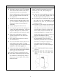
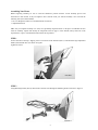
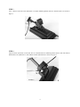
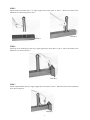
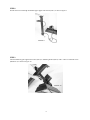
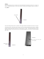
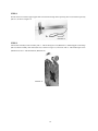
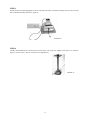
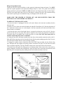
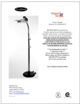
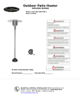
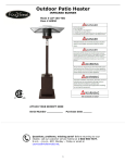
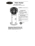
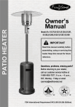
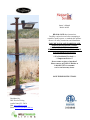
Owner’s Manual
Model: 60803
READ & SAVE these instructions
Carefully read and review before attempting to
assemble, install, operate, or maintain this product.
Observe all safety instructions and information.
FAILURE TO FOLLOW WARNINGS AND
OPERATIONAL INSTRUCTIONS
CONTAINED IN THIS MANUAL CAN
RESULT IN SEVERE PROPERTY DAMAGE
AND OR PERSONAL INJURY.
***For Residential Use Only***
***Important Notice***
Do not return to place of purchase!!
Please contact our Toll Free Hotline at
1-866-985-7877 for customer
service and warranty issues.
SAVE THESE INSTRUCTIONS
Distributed by:
Well Traveled Living
Amelia Island, FL 32034
Web: www.wtliving.com
Email: [email protected]
Safety Guidelines
Read this manual carefully to become knowledgeable about your heater and how to use it properly.
To help recognize this information, observe the following symbols.
Indicates a potentially hazardous situation which, if Indicates a potentially hazardous situation, if not
avoided, COULD result in serious injury or death.
not avoided, WILL result in serious injury or death.
Indicates a potentially hazardous situation which, if Indicates important information that if not followed,
not avoided, MAY cause moderate injury or damage to may cause damage to the equipment.
the equipment.
1
.
Risk of Fire.
There is always a risk of fire when working with a heater. Keep it away from
flammable liquids and any material that could easily catch fire.
2.
Risk of Fire.
3.
If the heater falls, this unit might start a fire.
Hot or Burn Hazard.
This unit may be hot at any time during its use especially around the head
and heating element.
4.
Electrical Hazard.
Disconnect all electric power before working on the unit.
There is a chance
of electric shock if you work on this unit with it still plugged into the wall.
5.
Electric Shock.
This unit uses electricity to operate. Do not use this heater around water or if the
cord has been damaged.
•
•
Improper treatment of the heater can damage it and also shorten its life span.
To prevent electrical shock follow electrical plug requirements on page 11 of this manual.
2
This appliance MUST be grounded.
* When using outdoors, we recommend using a certified GFI (Ground Fault Interrupt)
outlet to protect against electrical shock.
* All installations must be in accordance with I.E.E. safety regulations or the equivalent.
* Avoid the use of an extension cord with this appliance.
* Do not place any objects such as furniture, papers, clothing or curtains closer than 3 feet
to the front and sides of the heater.
PARTS LIST
1- IR Head unit w/Protective Shield with:
* Tilt Switch (safety cut off)
* On/Off Switch (PULL for ON, PUSH for OFF)
* Angle Adjustment Bar
* 1500 Watt quartz halogen bulb
* Swivel Bracket
* 15.5 foot, 14 AWG grounded electrical cord
2 – Mounting Bracket – attaches head unit to
telescopic pole
3 – Upper support tube section for telescopic body
4 – Telescopic Body – includes 2 sections (4-1 and
4-2) with 2 easy release clamp collars (4-3)
to allow for easy adjustment
5 – Adjustable table
6 – Top cover finishing piece
7 – Rounded end bracket
8 – L-shaped bracket
9 – Support Collar for telescopic body
10 – Base assembly with wheel assembly
11 – Protective vinyl cover (for use ONLY when
heater has completely cooled)
ALSO INCLUDED (not pictured):
Hardware packet :
Letter
Name
M6*12 Oval Head Screw
A
M4 Flat Washer
B
M4*10 Round Head Screw
C
M8*22 Hexagon Screw
D
M8 Flat Washer
E
M6*20 Oval Head Screw
F
M8*16 Hexagon Screw
G
3
Quantity
24 pieces
2 pieces
3 pieces
4 pieces
4 pieces
2 pieces
3 pieces
CAUTION!
Important Instructions
1. Read all instructions before using this heater.
2. This heater is hot when in use. To avoid burns,
do not let bare skin touch hot surfaces. Keep
combustible materials, such as furniture,
pillows, bedding, papers cloths, and curtains at
least 3 feet (0.9m) from the front, sides and
rear of the heater.
3. DO NOT leave heater unattended. Extreme
caution is necessary when any heater is used
by, or near, children or disabled persons, and
whenever the heater is left operating and
unattended.
4. Always unplug heater when not in use.
5. Do not operate any heater with a damaged cord
or plug, if the heater malfunctions, or has been
dropped or damaged in any manner. Return
heater to authorized service facility for repairs.
6. Heater can be used indoors or outdoors.
Operate a minimum of 3 feet (0.9m) from
people or objects.
7. Never operate heater near water or where it
can be knocked over.
8. Do not run cord under carpeting. Do not cover
cord with throw rugs, runners, or similar
coverings. Arrange cord away from traffic area
and where it will not be tripped over.
9. To disconnect heater, switch to OFF position
(push in switch located on head unit) and then
remove plug from electrical outlet.
10. Connect to properly grounded outlets only.
11. Do not insert or allow foreign objects to enter
any ventilation or exhaust opening; doing so
may cause an electrical shock or fire, or may
damage the heater.
12. To prevent a possible fire, do not block air
intakes or exhaust in any manner. Do not use on
soft surfaces, like a bed, where openings may
become blocked.
13. A heater has hot and sparking parts inside. Do
not use it in areas where gasoline, paint, or
flammable liquids are used or stored.
14. Use this heater only as described in this manual.
Any other use not recommended by the
manufacturer may cause fire, electrical shock,
or injury to persons.
15. Avoid the use of an extension cord because the
extension cord may overheat and cause a risk
of fire. However, if you must use an extension
cord, use either a 12 gauge or 14 gauge wire
which is rated not less than 1900 watts. The
recommended length for a 14 gauge is 0-50
feet but if you must use a longer cord, use a 12
gauge NO LONGER than 100 feet.
16. This unit comes equipped with a Safety Tilt
Switch mechanism. Power will shut off
automatically should the unit be accidentally
knocked over or tilted past 15 degrees. To
reset, unplug the unit from wall outlet,
reposition on a flat, level surface and plug in
again.
17. SAVE THESE INSTRUCTIONS for future
reference.
4
Assembling Your Heater
Before beginning assembly, be sure to read and familiarize yourself with the overall assembly process and
instructions in this manual. It may be helpful to have someone assist you with the assembly. You will need the
following tools (NOT INCLUDED):
** #2 or #3 Philips Screwdriver (or standard slotted screwdriver)
** Adjustable Wrench
Make sure you complete assembly on a clean, level, preferably carpeted location. A flat piece of cardboard will also
work for assembly. Unpack and identify all components listed on page 3 of this manual and lay them out on the
carpeted floor or piece of cardboard and then follow the steps below:
STEP 1
Loosen and remove the top 2 Tapping screws on each side of the head unit (Part 1) and attach the angle adjustment
handle (included with Part 1) as shown in Figure 1.
Tighten the screws.
FIGURE 1
STEP 2
Using Mounting bracket (Part 2), thread entire electrical cord through the Mounting bracket as shown in Figure 2.
FIGURE 2
5
STEP 3
Use 4 – M6*12 Oval head screws (Hardware A) to attach Mounting bracket (Part 2) to head unit (Part 1) as shown in
Figure 3.
FIGURE 3
STEP 4
Align tilt switch (black box on head unit, Part 1) to threaded holes on Mounting bracket (Part 2) and insert M4*10
Round head screws (Hardware C) with M4 Flat washers (Hardware B) as shown in Figure 4.
FIGURE 4
6
STEP 5
Attach Round end bracket (Part 7) to Upper support tube section (Part 3) with 4 – M6*12 Oval head screws
(Hardware A) as shown in Figures 5 and 6.
FIGURE 6
FIGURE 5
STEP 6
Attach Top cover finishing piece (Part 6) to Upper support tube section (Part 3) with 4 – M6*12 Oval head screws
(Hardware A) as shown in Figure 7.
FIGURE 7
STEP 7
Attach L-shaped bracket (Part 8) to Upper support tube section (Part 3) with 2 – M6*20 Oval head screws (Hardware
G) as shown in Figure 8.
FIGURE 8
7
STEP 8
Thread electrical cord through assembled Upper support tube section (Part 3) as show in Figure 9.
FIGURE 9
STEP 9
Attach assembled Upper support tube section (Part 3) to Mounting bracket (Part 2) with 4 – M6*12 Oval head screws
(Hardware A) as shown in Figure 10.
FIGURE 10
8
STEP 10
Locate Telescopic Body section 4-2 (NOTE: It has a small machined hole at the bottom of the section—see Figure 11)
and slide Adjustable Table (Part 5) over the end of section 4-2 making sure the adjustable clamps on the table are
facing DOWN.
SMALL HOLE
FIGURE 11
Now locate Telescopic Body section 4-1 (NOTE: It has a large round hole at the bottom of the section—see Figure
12) and slide section 4-1 down into section 4-2 until you can see the small machined hole from section 4-2 through
the large round hole at the bottom of section 4-1 as shown in Figure 13. Insert 1 – M4*10 Round Head Screw into the
small hole and tighten. This will prevent section 4-2 from sliding completely out of section 4-1 when the assembled
pole is lifted.
FIGURE 13
Insert
tighten
LARGE HOLE
FIGURE 12
9
screw
here
and
STEP 11
Thread electrical cord from Upper support tube section down through Telescopic body (Part 4-2) and Telescopic body
(Part 4-1) as shown in Figure 14.
FIGURE 14
STEP 12
Attach wheel assembly to base assembly with 3 – M8*16 Hexagon screws (Hardware I). Mount Support collar flange
(Part 9) to Base assembly with wheels (Part 10) as shown in Figure 15, and secure with 4 – M8*22 Hexagon screws
(Hardware D) and 4 -- M8 Flat Washers (Hardware E) .
FIGURE 15
10
STEP 13
Thread electrical cord through Support collar for telescopic base (Part 9) and Base assembly (Part 10) and out of the
hole on the Base assembly as shown in Figure 16.
FIGURE 16
STEP 14
Carefully lift assembled pole and head unit and insert lower end of pole into Support collar (Part 9) as shown in
Figure 17. Secure with 8 – M6*12 Oval head screws (Hardware A).
FIGURE 17
11
OPERATING INSTRUCTIONS
CAUTION!
This appliance MUST be grounded.
* When using outdoors, we recommend using a certified GFI (Ground Fault Interrupt)
outlet to protect against electrical shock.
* ALL installations must be in accordance with I.E.E. safety regulations or equivalent.
* Avoid the use of an extension cord with this appliance. If one is used, it must meet the requirements
as outlined in #15, “Important Instructions” on page 4 of this manual.
* Do not place any objects such as furniture, papers, clothing, or curtains closer than 3 feet to the front,
top or sides of this heater.
* ALWAYS unplug the heater when it is not in use.
For optimal performance and safety concerns, we HIGHLY recommend that the Infrared Heating
System be operated at a minimum of 95” in height or the maximum extended length of the telescopic
body sections. You should only lower the height of the unit for storage purposes when it has
completely cooled and is not in operation.
To adjust the IR telescopic body:
Pull up on the release levers of the tightening clamps and adjust tension using
the tension knobs. Raise and lower the telescopic sections and/or swivel
to desired position and then push in clamp levers to secure. DO NOT
over tighten tension knobs. There should only be a moderate amount
of tension to maintain the telescopic position of your heater.
Step 1
Before turning on your Infrared Heating System, check to make sure the “On/Off” switch located on
the tilt switch (black box) of the head unit is pulled OUT or in the ON position (note: to turn the heater
“Off”, push in the switch). Next, extend all 3 telescopic sections to their maximum extended length.
Release clamp levers and pull up on each of the sectional steel tubes until each tube stops. Then push
in clamp levers to secure sections in place. Adjust the tension knobs as needed to maintain height
position.
Step 2
The Infrared Heating System comes equipped with a heavy duty, 14 AWG gauge wire
and grounded plug. This appliance must be used with an outlet that has been installed
and grounded in accordance with local codes and ordinances. Make sure the heater is
connected to an outlet having the same configuration as shown in the figure shown to
the right. DO NOT use an adapter with this product. Check with a licensed electrician if
the grounding instructions are not understood completely or if the wall outlet does not
match the plug.
Step 3
Your Mojave Sun, Infrared Heating System is ready to enjoy. Plug the appliance in and enjoy the
warmth!
12
Specifications
Model:
Voltage:
Amps:
Wattage:
Lamp Type:
Minimum Operational Height:
Assembled Weight:
Head Unit Dimensions:
Heater Assembled Dimensions:
60803
120 volts
12.5 amps
1500 watts
Quartz Halogen
7 ft., 11 in. (95 in.)
69 lbs.
25.6” x 21.6” x 18.1”
15.75” diameter base, 95” height
Storage
* Always UNPLUG the unit when not in use.
* Once the head unit has completely cooled, store the heater with the protective vinyl cover on the
head unit.
* When heater is not in use for an extended period of time, store in a covered location that is dry and
out of the weather. Make sure the heater is stored in a location that is out of the way of people and pets
that may accidentally knock the heater over or damage the appliance. Before storing the heater, make
sure the electrical cord is coiled and out of the way.
* When storing, ALWAYS lower the telescopic pole to its lowest level. This will make it easier to
store and reduce the risk of any accidental tipping over of the heater.
Maintenance
Your Infrared Heating System is virtually maintenance free! A minute to wipe down exposed surfaces
is all it takes to maintain your heater.
* Head unit and shield: Use a non-abrasive cleaner and a soft cloth to wipe off debris and dirt from the
exposed surfaces. NEVER spray liquids or cleaners into the housing area where the halogen lamp
is located. Do not try to disassemble of clean the inner cavity where the halogen lamp is located. For
any maintenance on the head unit, please call the toll free customer service hotline.
* Telescopic pole and curved arm components: These can easily be wiped clean using a non-abrasive
cleaner and a soft cloth.
* Base with wheel assembly: Use non-abrasive cleaner and a soft cloth. Any scratches, chips or rust
spots can be touched up using an exterior matte finish paint.
13
Halogen Lamp Replacement
Contact the toll free customer hotline to order approved replacement lamps and parts. Use ONLY
approved original equipment and replacement halogen lamps to ensure safe, proper and maximum
output operation of your heater. NOTE: Do NOT touch the new halogen lamp with your bare fingers.
Oils from your hand could reduce the life of the lamp by causing a heat spot. We recommend using
clean cotton or plastic gloves to handle the lamp. A clean paper towel will also work.
MAKE SURE THE HEATER IS TURNED OFF AND DISCONNECTED FROM THE
ELECTRICAL OUTLET BEFORE YOU BEGIN!!!!
TO REPLACE THE HALOGEN LAMP:
1. Be sure the heater is unplugged from the wall outlet. Remove the head unit assembly from the
telescopic pole.
2. Remove 8 screws from each end of the head unit and pull off end plates (#2). Note the placement of
the 2 small sheet metal screws on each end plate. Also note end plate side with beveled holes faces
outward when re-assembled.
3. Pull out and remove the left and right front air vent panels and protective wire grill (#3). Note the
position of end clips on vent panel. They must be aligned as close to the end connectors of lamp tube
as possible when re-assembled. Pull or push into place as needed. DO NOT allow metal parts to
touch the actual lamp tube when re-assembled.
4. Gently pull out entire old lamp assembly from the clips at the terminal connection ends (#4 & 5).
Slide and lift the connection ends out from the friction clips by gently pushing apart the clips. Unscrew
wire leads from terminal. Remove entire old lamp assembly.
5. Using gloves, gently re-insert connection ends of the NEW lamp assembly into the friction clips
(#4). Pull apart the clips slightly and gently push the connectors into place. Do not allow the metal
clips to touch the lamp tube. The clips should be about at the center point of the end connectors.
6. Re-install the safety grill (fits along grooves in housing body), then re-insert the vent panels by
gently pushing the end clips into housing body. Align clip ends close to the lamp end connectors and
push into place. Re-attach end plates making sure the side with beveled holes faces out.
14
Troubleshooting
Problem
Unit fails to turn on.
Solution
Check electrical plug connection at wall outlet for a complete, snug fit.
Check to make sure the “On/Off” switch located on tilt switch is pulled
OUT or in the “On” position.
Check GFI and reset circuit breaker if needed.
If unit is plugged into a wall outlet wired to an On/Off switch, make sure
switch is in On Position.
Reset safety tilt switch. Unplug unit from wall outlet and re-position on
flat, level surface. Plug heater back into outlet.
Damaged halogen bulb. Call customer service hotline.
Telescopic pole slips down.
Tighten black tension knobs on clamp collars.
Telescopic pole is unsteady.
Tighten screws on support collar at base.
Telescopic pole will not adjust.
Electrical cord may be kinked. Gently pull end of cord until taut.
Head unit is loose or unsteady.
Tighten screws on mounting bracket.
Head unit is hard to adjust.
Loosen connecting bolts/nuts at adjustment bracket.
Smoke appears from head unit.
Unplug IMMEDIATELY and call customer service hotline.
Weak output from halogen lamp.
Life span of lamp has been reached or damaged lamp. Call customer
service hotline for assistance.
NOTE: This product comes with a limited one year warranty.
After the warranty period, you may purchase replacement bulbs
from www.patiomarket.com at the lowest cost available.
15
Distributed By: Well Traveled Living 716 S 8th Street Amelia Island, FL 32034 Toll Free: 866‐WTL‐SUPP Web: www.wtliving.com Email: [email protected] 1 YEAR LIMITED WARRANTY – Customers in the Continental US
All components are warranted for a period of 1 year after date of purchase by the original owner against defects in
materials and workmanship under normal use. This warranty does NOT cover normal wear and weathering, assembly
and/or maintenance OR use in a commercial application. At Well Traveled Living’s sole discretion, products under
warranty will be repaired and/or replaced at no charge to the customer. Any returns sent back to Well Traveled Living
must be sent via prepaid freight and in the original retail packaging.
For warranty service contact Well Traveled Living at the address, phone numbers or internet site and email listed in this
owner’s manual. Be sure to have your sales receipt, date of purchase and catalogue/model numbers available when
calling. All warranty service will be coordinated by the Well Traveled Living’s, Amelia Island, Florida service center.
This warranty is extended only to the original purchaser. Proof of purchase will be required before warranty service is
rendered. The sales receipt is the only valid proof of purchase. This warranty only covers failures due to defects in
materials or workmanship which occur during normal use. Failures and/or damage which result from accident, negligence,
misuse, abuse, neglect, mishandling, alteration or modification, failure to maintain, improper assembly or maintenance,
service by unauthorized agency or use of unauthorized components or damage that is attributable to acts of God are NOT
covered.
***THERE ARE NO EXPRESS WARRANTIES EXCEPT AS LISTED ABOVE***
***PURCHASER ASSUMES ALL RISKS IN THE ASSEMBLY AND OPERATION OF THIS UNIT***
***FAILURE TO FOLLOW WARNINGS AND OPERATIONAL INSTRUCTIONS CONTAINED IN THIS MANUAL CAN
RESULT IN SEVERE PROPERTY DAMAGE AND/OR PERSONAL INJURY***
IN NO EVENT WILL WELL TRAVELED LIVING, OR ITS DIRECTORS, OFFICERS OR AGENTS BE LIABLE TO THE
PURCHASER OR ANY THIRD PARTY, WHETHER IN CONTRACT, IN TORT, OR ON ANY OTHER BASIS, FOR ANY
INDIRECT, SPECIAL, PUNITIVE, EXEMPLARY, CONSEQUENTIAL, OR INCIDENTAL LOSS, COST, OR DAMAGE
ARISING OUT OF OR IN CONNECTION WITH THE SALE, MAINTENANCE, USE, OR INABILITY TO USE THE
PRODUCT, EVEN IF WELL TRAVELED LIVING OR ITS DIRECTORS, OFFICERS OR AGENTS HAVE BEEN
ADVISED OF THE POSSIBILITY OF SUCH LOSSES, COSTS OR DAMAGES, OR IF SUCH LOSSES, COSTS, OR
DAMAGES ARE FORESEEABLE. IN NO EVENT WILL WELL TRAVELED LIVING, OR ITS OFFICERS, DIRECTORS,
OR AGENTS BE LIABLE FOR ANY DIRECT LOSSES, COSTS OR DAMAGES THAT EXCEED THE PURCHASE
PRICE OF THE PRODUCT.
SOME JURISDICTIONS DO NOT ALLOW THE EXCLUSION OR LIMITATION OF INCIDENTAL OR CONSEQUENTIAL
DAMAGES, SO THE ABOVE LIMITATION OR EXCLUSION MAY NOT APPLY TO THE PURCHASER.
This limited warranty gives you specific legal rights and you may also have other rights which vary from jurisdiction to
jurisdiction. The provisions of the United Nations Convention on Contracts for the Sales of Goods shall not apply to this
limited warranty or the sale of products covered by this limited warranty.
***IMPORTANT NOTICE*** ‐Do NOT return to place of purchase‐ For customer service and warranty issues contact our Customer Service Center at: (866)‐985‐7877 OR Email: [email protected] Customer Service Hours: Mon. – Fri. 9:00 a.m. – 6:00 p.m. (EST) Fire Sense®, Mojave Sun ™, and Well Traveled Living® are registered trademarks of Well Traveled Imports, Inc®. All assembly instruction presentations are the property of Well Traveled Imports, Inc.® and are protected by U.S. copyrights and trademarks. All rights reserved.