1
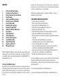
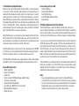
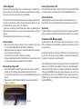
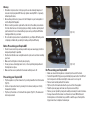
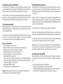
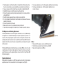
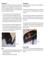
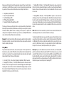
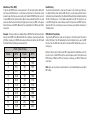
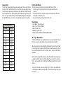
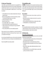
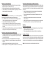
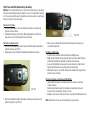
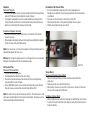
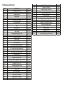
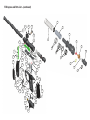
OWNER’S MANUAL CONTENTS 1. 2. 3. 4. 5. 6. 7. 8. 9. 10. 11. 12. 13. 14. 15. 16. 17. 18. Rules for Safe Marker Handling Introduction and Specifications Battery Replacement and Life Indicator Basic Operation Compressed Air/Nitrogen Supply Installing a Loader and Paintballs Firing the Empire AXE Break Beam Eyes Operation Unloading the Empire AXE Regulator and Velocity Adjustments Programming Trigger Adjustments General Maintenance Storage and Transportation Assembly/Disassembly Trouble Shooting Guide Diagrams and Parts List Warranty Information Read the full Operator’s Manual for technical information, usage instructions, and maintenance tips for your Axe marker. The full manual can be found on the CD enclosed with the marker or by contacting Paintball Solutions at 1-800-220-3222 or at www.paintballsolutions.com. 1. Rules for Safe Marker Handling Important: Never carry your Empire AXE uncased when not on a playing field. The nonpaintball playing public and law enforcement personnel may not be able to distinguish between a paintball marker and firearm. For your own safety and to protect the image of the sport, always carry your Empire AXE in a suitable marker case or in the box in which it came in. Safety and safe marker handling are the most important aspects of paintball sports. Please practice each of the following steps with an unloaded marker before attempting to operate your marker with an air source and paintballs. Read this entire manual before loading, or installing an air cylinder, or in any way attempting to operate the marker *READ OWNER’S MANUAL BEFORE USING* • Treat every marker as if it were loaded. • Never look down the barrel of a paintball marker. • Keep your finger off the trigger until ready to shoot. • Never point the marker at anything you don’t wish to shoot. • Keep the marker off until ready to shoot. • Keep the barrel-blocking device in/on the marker’s barrel when not shooting. • Always remove paintballs and air source before disassembly. • After removing air source, point marker in safe direction and discharge until marker is degassed. • Store the marker unloaded and degassed in a secure place. • Follow warnings listed on the air source for handling and storage • Do not shoot at fragile objects such as windows. • Every person within range must wear eye, face, and ear protection designed specifically to stop paintballs and meeting ASTM standard F1776. • Always measure your marker’s velocity before playing paintball and never shoot at velocities in excess of 300 feet-per-second (91.44 meters). • Remember that the ultimate safety device is you, the operator. This is not a toy. Misuse may cause serious injury or death. Eye protection designed specifically for paintball must be worn by the user and persons within range. Recommend 18 years of age or older to purchase. Persons under 18 years of age must have adult supervision. For manuals and warranty details, go to: paintballsolutions.com For manuals in other languages (where applicable), go to: paintballsolutions.com 2. Introduction and Specifications Welcome to the world of the Empire AXE. The Empire AXE is a modern culmination in the pursuit of speed, technology, weight reduction, and overall performance. It started with radical imaginative concepts, which in turn inspired years of research and development, plus countless hours of testing and engineering. As a result, the Empire AXE features innovative electronic and pneumatic technologies that challenge the paradigm that formerly defined “how a high performance paintball marker should function”. The Empire AXE is precision engineered from aircraft-grade aluminum to meet the demands of the most competitive players, teams, and climates. The ultimate intent of the Empire AXE is to exceed your expectations. Empire Paintball expects you to play hard and play frequently and thus the Empire AXE was built with this in mind. All internal parts, wear, and contact surfaces have been heat treated or hard anodized. The toughest and most resilient materials and components have been used in the construction of this marker. The Empire AXE operates on low-pressure. The main operating pressure is 180–200 psi. The pressure can be nominally adjusted and monitored visually via the gauge on the bottom-line regulator. There is no secondary regulator to worry about. The Empire AXE uses .68 caliber, water-soluble paintballs or reballs, readily available at paintball pro-shops, commercial playing fields, and many sporting goods stores. Empire AXE Specifications • Model- Empire AXE • Barrel- 12” Ported Barrel • Caliber- .68 • Action- Semi Auto, PSP/Millen Ramping, and NXL Full Auto • Air Source- Compressed Air • Battery- One 9-Volt (Alkaline Only) • Cycle Rate- Up to 20 BPS with stock circuit board • Main Body Material- Aluminum • Weight- 36 ounces Included with your Empire AXE • 12” Barrel (.691 bore) • Spares and Allen Wrenches • Barrel-Blocking Device • One 9-Volt Alkaline Battery (installed) • Owners Manual 3. Battery Replacement and Life Indicator The Empire AXE requires a single 9-volt battery as the electronic power source. The use of brand-name batteries is recommended. The 9-volt battery is located in the front fore-grip. The battery is accessed through the removable left side panel on the front fore-grip. Confirm that the marker is off before changing or installing the battery. Loosen the screw on the left side of the fore grip by turning it counter-clockwise with a 5/64” Allen wrench and lift fore grip door off. If there is already a battery in the foregrip, carefully disconnect the battery from the battery harness, and then connect a fresh 9-Volt battery to the harness. Re-insert the battery and harness back into the battery compartment with the harness pointed down towards the bottom of the grip. Make sure that there are no abrupt kinks and the wires are comfortably placed. Do not force them into place. Then re-install the fore grip removable door. The Empire AXE also has a battery life indicator. If in standard operation and the LED flashes green, the battery is good; if the LED is flashes orange, the battery is fairly depleted and should be changed soon; if the LED is flashes red, then the battery is depleted and should be replaced immediately. Notes: • Some rechargeable batteries may be too large for the Empire AXE battery compartment. If they don’t fit, please don’t force them as this may cause damage. • The stock circuit board does not store user-defined settings. You must change the battery quickly to keep your user-defined setting. If the battery is not changed quickly the circuit board will revert to the factory default settings. 4. Basic Operation Safety and safe marker handling are the most important aspects of paintball sports. Please practice each of the following steps with an unloaded marker before attempting to charge your marker with compressed air and paintballs. • Keep your finger out of the trigger guard and away from the trigger; point the barrel of the marker in a safe direction at all times. Keep the marker turned off when not in use. The Empire AXE uses a power switch for its safety device. • Always use a barrel plug or barrel-blocking device. Always use ASTM-approved paintball-specific eye protection in any areas where paintball markers may be discharged. • Remember that the ultimate safety device is you, the operator. Barrel Installation • Make sure the marker is degassed, loader removed, no paintballs in the feed neck or breech, and the Empire AXE is turned off before installing barrel. • While pointing marker in a safe direction, place the threaded end of the barrel into the front opening of the marker body. • Turn the barrel clockwise until it stops (do not over tighten). • Install a barrel-blocking device which is included. This can be a barrel plug or other such device that prevents the accidental discharge of paintballs. Powering On your Empire AXE • To turn the Empire AXE on, locate the power button on the back side of the front fore-grip, in front of the trigger guard and directly under the LED (Fig. 4.1). • Push and hold the power button for 2 seconds and the LED light will turn green and then red. • Release button and the LED will intermittently flash green indicating that the marker is now turned on. (Fig. 4.1) Powering Off your Empire AXE Push and hold the power button on the front fore grip for 2 seconds and the LED will turn solid red and then green. Release button and the Empire AXE will turn off. Automatic Off feature The Empire AXE also has an automatic off feature. If you accidentally leave your Empire AXE powered up, it will shut itself off after approximately 1 hour of inactivity. Eye Function The Empire AXE board is pre-programmed to activate the eye system each time the marker is powered up. Read Section 8 (Break Beam Eyes Operation) for more details. 5. Compressed Air/Nitrogen Supply The Empire AXE is designed to work with compressed air/nitrogen only. Do not use CO2, as it will damage your Empire AXE. Low-pressure output compressed air tanks are recommended. Consult the place where you purchased your Empire AXE, or a recognized and competent air smith, for instruction in the safe handling of compressed-air cylinders before purchasing or connecting one to your Empire AXE. The Empire AXE utilizes a fully functional regulator at the bottom of the grip frame that doubles as an on/off ASA (air source adapter) or receiver for a standard threaded preset output compressed air systems. It is strongly recommended that a very high-flow “low-pressure” (400–450 psi) fixed-output system is utilized as an air source for your Empire AXE. Using a “high pressure” (750–850 psi) output compressed air tank is acceptable. If you are using an adjustable output regulator system, the output pressure should be 400–500 psi. Warning: • Remember compressed air or nitrogen systems can be extremely dangerous if misused or improperly handLED. Use only cylinders meeting D.O.T. or regionally defined specifications. • Never add any lubricants or greases into the fill adapter on your tank regulator or into the Empire AXE regulator. • When connecting a remote system with a slide check, the sudden pressurization from the slide check can force the poppet open briefly, sometimes pushing a ball past the detents. It is recommended that you pressurize your Empire AXE before loading paintballs into your loader. • Do not install compressed air or load paintballs into your Empire AXE until you feel completely confident with your ability to handle your Empire AXE safely. (Fig. 5.1) Before Pressurizing your Empire AXE • • • • • Check to make sure that you and anyone within range are wearing eye protection designed specifically for paintball. Double check that all screws are tightened and no parts are loose before installing your tank. Make sure the bolt guide is locked in place properly. Ensure you have a barrel plug, barrel sock, or other specifically designed barrel blocking device in place. Make sure there are no paintballs in the marker and the power is off. Pressurizing your Empire AXE • • • Flip the regulators on/off arm forward so it’s pointing toward the front of the marker (Fig. 5.1). Install a compressed air tank, by screwing it in clockwise; making sure it’s fully threaded into the ASA. Flip the on/off arm back so it’s flush with the regulator (Fig. 5.2). The marker will become pressurized. (Fig. 5.2) De-Pressurizing your Empire AXE • • • • • • • Make sure a barrel-blocking device is installed in/on the end of the barrel. Turn the Empire AXE off by pressing and holding the power button. The LED will turn from green to red. Observe the light to make sure it is no longer lit. Remove loader and all paintballs from marker. Flip the on/off arm forward and allow the gas to vent from the regulator. Read the pressure gauge and make sure the pressure reads 0 psi. Remove your air cylinder by slowly and carefully unscrewing it counter-clockwise. Air may remain within the marker once the tank is removed. While the barrel blocking device is still installed, turn your AXE on with the eyes off and pull the trigger a few times to deplete all remaining air. 6. Installing a Loader and Paintballs 8. Break Beam Eyes Operation The Empire AXE comes equipped to accept standard-gravity feed loaders as well as most agitating and force-feed loaders. Fit the loader directly into the feed neck. It might be necessary to adjust the feed necks clamping screw to your loader. The Empire AXE uses a break beam eye system to determine the presence or absence of a ball for the purposes of reduced paint breakage and optimum rates of fire. The Empire AXE board is pre-programmed to activate the eye system each time the marker is powered up. The Empire AXE uses .68 caliber, water-soluble paintballs, readily available at paintball pro-shops, commercial playing fields, and many sporting goods stores. The paintballs feed from the loader through the neck and into the breech of the marker. 7. Firing the Empire AXE Warning: Always keep your Empire AXE pointed in a safe direction! Everyone within firing range should always use paintball-approved eye and face protection in the presence of live paintball markers. Keep your finger out of the trigger guard and away from the trigger; point the barrel of your marker in a safe direction at all times during this process. Be sure your goggles are securely in place and make sure the Empire AXE is powered off. Firing your Empire AXE • Place an empty loader onto the marker. • Make sure that the loader is securely mounted and clamped in place. • Install a compressed air cylinder, pressurizing the marker. • Put the paintballs into the loader and turn the loader on. • Remove the barrel plug, sock, or barrel-blocking device. • Aim the Empire AXE in a safe direction. • Turn the marker on by pushing the power button for 2 seconds until the LED light changes from solid green to solid red; then release button and the LED should go to a rapid flashing green if a ball is present. • Aim the Empire AXE at the target. • Pull the trigger with a smooth squeezing motion. Caution: When the game you are playing is over, remember to place the barrel blocking device onto your barrel and turn the marker off. To turn the eyes off, ensure that there are no paintballs in the Empire AXE breech or feed-neck, make sure the marker is switched off, and then while pulling and holding the trigger, turn the marker on. A quick double blinking green LED will indicate that the eye system has been deactivated. To turn the eyes back on, simply tap the power button one time quickly. A slow consistent single flashing green LED indicates that the eyes are on with no ball in the breech and a rapid flashing green LED indicates that there is a ball in the breech. For optimal performance of the Empire AXE eyes, keep the inside of the Empire AXE breech clean and clear of broken paint, paint residue, or other debris. Although the eyes can be cleaned via cleaning the breech of the Empire AXE marker, if the eyes need to be accessed please follow the steps outlined in the Empire AXE Assembly-Disassembly section of this manual to remove the sensor board. 9. Unloading the Empire AXE Warning: Always keep your Empire AXE pointed in a safe direction and always keep your protective eye, face and ear wear on until marker is completely unloaded and safe. • • • Be sure your finger is away from the trigger area. Place the barrel-blocking device in/on the end of the barrel. Turn the Empire AXE off by pressing and holding the power button. The LED will turn from green to red. Observe the LED to make sure it is no longer lit. • • • • • • • • • Flip the regulators on/off arm forward so it’s facing the front of the marker; allow the air to vent and remove your air cylinder by unscrewing it counter-clockwise. If you are using an electronic loader make sure loader is completely turned off. Slightly tilt the marker so that the loader is lower than the body. Remove the loader by undoing the clamp and spinning it in a clockwise direction and gently lifting it. Read the pressure gauge and make sure the pressure reads 0 psi. Do not look down the barrel but look down the feed neck to make sure there are no paintballs in the breech. Remove the barrel from the marker. Make sure there are no more paintballs remaining in the barrel. Your marker is now ready to be stored in its box or marker case until its next use. • To increase output pressure— Turn the regulator adjustment screw clockwise. • To decrease output pressure— Turn the regulator adjustment screw counter-clockwise. 10. Regulator and Velocity Adjustment The Empire AXE utilizes a bottom-line regulator that doubles as an on/off ASA adapter and regulator for a standard threaded pre-set output compressed air systems or remote hose. This unique regulator system channels air through the air transfer tube, eliminating the need for external macro line and fittings. The Empire AXE bottom-line regulator controls the amount of air pressure going from your compressed air system into the marker. The Empire AXE regulator should be factory pre-set at about 190 psi, as this is the best operating pressure for proper marker operation. However, if over time you do need to adjust the pressure, use the regulator adjuster screw on the front of your Empire AXE bottom-line regulator. Regulator Adjustment If adjustments are needed use a 3/16” Allen wrench and insert it into the regulator adjustment screw. This is located in the front of the regulator; see (Fig. 10.1). (Fig. 10.1) Notes: • Always watch the gauge as you are adjusting the pressure. • The bottom-line regulator should not be disassembLED. • Never set the regulator above 200 psi. To increase (+) velocity, unscrew or loosen the velocity adjustment screw by turning it counter-clockwise. Rotate the velocity adjustment screw counterclockwise in small increments (1/4 turn or less), stopping between slight turns to test velocity, until desired velocity is achieved. Do not back the adjuster out passed being flush. Stop if you hear an air leak, and adjust back in a 1/4 turn. A paintball specific radar chronograph should be used to accurately measure your velocity. • To decrease (-) velocity, tighten or screw-in the velocity adjustment screw by turning it clockwise. Rotate the velocity adjustment screw clockwise in small increments (1/4 turn or less), stopping between slight turns to test velocity, until desired velocity is achieved. A paintball-specific radar chronograph should be used to accurately measure your markers velocity. (Fig. 10.2) Notes: • This marker was designed with safety and safety standards in mind. If you attempt to shoot paintballs at a higher velocity than established safety standards, the marker may not function properly. • Check the velocity every time before using your Empire AXE. Warning: Before adjusting functions, remove the air source from the Empire AXE and install barrel-blocking device. The board inside your Empire AXE features 5 functions and uses a 3-color LED indicator on the backside of the front fore-grip to indicate functions and modes during programming. To adjust the board settings, place the Empire AXE on a flat surface with barrel pointing to the left. Using a 5/64” Allen wrench, loosen the screw that secures the removable fore grip door, remove the door, and set aside. This will expose the battery and the circuit board. Locate the two buttons which are used to adjust the settings. The function button (B) is a small black button on the rear of the board, to the left and slightly above the power button (A); see Fig.11.1 It is not necessary to remove the board from the housing in order to manage settings. B. • 11. Programming A. (Fig. 11.1) Adjusting Velocity At the back of the Empire AXE main body is the bolt guide cap. The Allen screw in the bolt guide cap serves as your velocity adjuster. Confirm that the pressure on your Empire AXE bottom-line regulator is at 180–200 psi. Then you can increase or decrease the velocity on your Empire AXE by tightening or loosening the velocity adjustment screw, with a 1/4” inch Allen wrench; see Fig. 10.2. Functions and Modes The Empire AXE must be off to begin managing functions. While the Empire AXE is off, press the function button (B) to access one of the 5 different functions and make adjustments. Once you push the function button the appropriate amount of times to get into the desired function, the LED will flash a specific color per the descriptions below followed by a number of flashes which will indicate the current setting in that function. • • • • • Firing Modes (Solid Red LED) Rate of Fire (Solid Green LED) Dwell (Solid Orange LED) BIP Delay (Flashing Red LED) Ramping Point (Quick-Flashing Green LED) To increase or decrease a setting of a function, use the power button (A) and function button (B). The power button (A) will decrease a setting by one every time it is pushed. The function button (B) will increase a setting by one every time it is pushed. The setting can be changed when the function you select has a solid light LED which will come on before the board flashes the current setting. Example: Press the function button (B) one time and you will be in function 1 which is firing modes (solid red), or press the function button 3 times and you will be in function 3 which is dwell (solid orange). Firing Modes To get into the firing mode function, make sure the power is off; then push the function button one time and the LED will turn to red and then flash to indicate the firing mode that it is currently in. For example the default mode is Semi-Auto which will be demonstrated by 1 flash. There are 4 firing modes: • Semi-Auto (1 Flash) — One shot per trigger pull, defaulted to 20 bps maximum. • Ramping/PSP (2 Flashes) — The Empire AXE will operate in semi-auto mode for the first 3 shots; then if player achieves the maximum trigger pull as defined by the ramping point value in function 5, which is defaulted to 4 trigger pulls per second for this mode, the Empire AXE will ramp to the rate of fire value in function 2, which is defaulted to 13 shots per second for this mode. • Full-Auto/NXL (3 Flashes) — The Empire AXE will operate in semi-auto mode for the first 3 shots; then pull and hold trigger on the 4th shot, and the Empire AXE will fire full-auto at the rate of fire value in function 2, which is defaulted to 13 shots per second for this mode. • Ramping/Millen. (4 Flashes) — The Empire AXE will operate in a semi-auto mode until player achieves the maximum trigger pull as defined by the ramping point value in function 5, which is defaulted to 6 trigger pulls per second for this mode. At that point, and as long as 6 trigger pulls per second are maintained, the Empire AXE will ramp to the rate of fire value in function 2, which is defaulted to 10 shots per second for this mode. Note: After modes 2 –4 are selected, it is possible to raise or lower both the rate of fire and ramping point values in case the tournament rules change. To cycle through the firing modes you use both the power and function buttons. Once you push the function button one time to get into the firing modes the LED will flash red. While the LED is lit red, push the function button (B) to cycle up (from 1 for semiauto to 4 for NXL full auto) and to go the opposite direction (from 4 at NXL full auto through to 1 for semi-auto). Use the power button (A) to cycle down. Example: If you are in the default semi-auto mode and want to go to full-auto/NXL, push the function button (B) twice while the LED is lit red. Upon release you should see the LED flash red 3 times. To move from full-auto/NXL to ramping/PSP, push the function button (B) one time to get into firing modes, then while LED is lit solid red, push power button (A) one time and release. The LED should flash red two times to indicate that you are now in firing mode 2-ramping/PSP. Max Rate-of-Fire (ROF) To get into the ROF function, make sure power is off, then push function button (B) two times and LED will turn to a solid green and then flash to indicate the current maximum rate of fire that you are currently set to. Default is 20 BPS (balls per second). To adjust ROF push the function button (B) two times and while the LED is lit a solid green use either the function button (to toggle up or increase your ROF) or the power button (to decrease the ROF). Max rate of fire is adjustable from 8–20 bps, with .5 bps increments. Dwell Setting To get into the dwell function, make sure the power is off, and then push the function button (B) three times and the LED will turn to a solid orange and then flash to indicate the current dwell setting. The Empire AXE dwell setting is defaulted at setting 28 (28 x .25 milliseconds = 7 ms). Dwell is adjustable from 1–45. This function is also controlLED through the same techniques used for firing modes and ROF functions, while the LED is lit a solid orange, increase or decrease your dwell by increments of .25 milliseconds. Example: To start you will be in a default setting of 20 BPS. Push the function button twice to get into ROF mode. While the LED is lit a solid green, press the power button (A) 5 times to take you to 15 BPS. Upon releasing the function button, the LED should then blink 15 times indicating your new rate of fire. BIP (Ball in Place) Delay To get into the BIP function, make sure the power is off, and then push the function button (B) 4 times. The LED will quickly flash red to indicate that you are in the BIP function. Then the LED will slowly flash to indicate the BIP setting that you are currently using. ROF (rate of fire) Flash 1 2 3 4 5 6 7 8 9 10 11 12 13 BPS 8.0 8.5 9.0 9.5 10.0 10.5 11.0 11.5 12.0 12.5 13.0 13.5 14.0 Flash 14 15 16 17 18 19 20 21 22 23 24 25 BPS 14.5 15.0 15.5 16.0 16.5 17.0 17.5 18.0 18.8 19.0 19.5 20.0 Default is (5) (one flash =1 millisecond). BIP is adjustable from 1–40 milliseconds. This function is also controlLED through the same techniques used for firing modes and ROF functions. While the LED is red, increase or decrease your BIP in 1 millisecond increments. Note: If you are not using a force-feed loader, it is recommended that you use a higher BIP setting. Ramping Point To get into the ramping point function make sure the power is off, then push the function button 5 times and the LED will turn to a quickly flashing green and then slowly flash to indicate the ramping point setting you are currently using. The default ramping point for PSP firing mode is 8 flashes (4 BPS). The default ramping point when firing mode is changed to millennium firing mode is 10 (5 BPS). Ramping point is adjustable from (3– 9 BPS). Please see chart for corresponding flashes/pulls to ramp settings. Ramping Point Flash 6 7 8 9 10 11 12 13 14 15 16 17 18 BPS 3.0 3.5 4.0 4.5 5.0 5.5 6.0 6.5 7.0 7.5 8.0 8.5 9.0 Factory Board Reset There are three ways to reset the circuit board to default factory settings. • Turn the power off then push the function button and power button at the same time. • Remove the battery then simultaneously push and hold the function button and power button for a full 10 seconds. • Disconnect the battery and leave it idle for 15 seconds. Board Defaults 1. Firing Modes – 1 blink (Semi-auto) 2. Rate of Fire – 25 blinks (20 BPS) 3. Dwell - 28 blinks (7 ms) 4. BIP Delay – 5 blinks (5 ms) 5. Ramping Point – 8 (4 BPS) for PSP, 10 (5 BPS) for Millen. 12. Trigger Adjustments The Empire AXE trigger can be adjusted by the four set screws in the trigger. Three of the set screws can be adjusted without removing the trigger frame assembly. When a trigger pull is recognized, the LED will quickly flash a dim red for each trigger pull. If no trigger pull is recognized, the LED flashes normally based on the status of the eyes and battery power level. If the trigger is held in, the dim red LED will stay illuminated. Before making any trigger adjustments, de-gas the Empire AXE, make sure the gauge reads 0 psi, and then switch on the Empire AXE with eyes turned off to easily monitor the current activation point by watching the LED, while listening to the solenoid clicking. You will notice three set screws in your trigger (Fig. 12.1). These can be adjusted with a 1/16” Allen wrench. Make small adjustments and check that the trigger is activating the solenoid. 12. Trigger Adjustments.....(continued). 13. General Maintenance CAUTION: Before attempting to perform any maintenance operations, make sure that all paintballs and air sources have been removed from the marker and that the regulator gauge reads 0 psi. Install a barrel-blocking device, and push the power button and hold for over 2 seconds until the LED light changes from red to green. Keep the Empire AXE power off. Keep your Empire AXE clean and lubricated to eliminate the friction that would prevent reliable operation. It is recommended that you clean and lube the marker before each use. 1 2 3 (Fig.12.1) • • • • The (1) first set screw located in the top of the trigger adjusts forward movement, and forward stop point. The (2) second set screw adjusts the rear movement range, and rear stop point. The (3) third set screw located at the bottom of the trigger adjusts the trigger magnetic return. Turn it clockwise to increase the return strength and counter clockwise to decrease the return strength. The first screw adjusts the trigger activation point. This screw can only be adjusted once the frame or trigger has been removed. It is recommended that you do not adjust the factory setting of this set screw as setting this set screw to high may cause damage to the trigger switch. Notes: • Normal activity may cause set screws to back out of adjustment. If necessary use blue loctite to help keep them set correctly. However do not use an excessive amount and allow the blue loctite to dry overnight before using your Empire AXE. • If any of the set screws are over adjusted in any direction the Empire AXE may not fire. • If the trigger travel is adjusted too short, the Empire AXE may fire on its own, repeatedly and/or uncontrollably. Do not use oil or petroleum-based lubricants in the lubrication of this marker. Teflon or silicon (non-spray only) lubricants designed for use on O-rings may be used for lubrication for the bolt, bolt guide and poppet area only. Dow 33 or the include factory grease is recommended. External Cleaning Use a clean cloth, dampened with water to clean the outside of the Empire AXE. Do not use any chemicals, as you may damage the protective finish. Warning: Do not rinse the Empire AXE under water, as you may damage the marker’s electronics. Internal Cleaning and Greasing The Empire AXE is designed for easy access to the bolt guide assembly without removing any hardware. On the back of the Empire AXE is a push button to allow such access for cleaning and maintenance. Refer to Section 15 for instructions on bolt guide removal. 14. Storage and Transportation 15. Assembly/Disassembly Caution: Never carry your Empire AXE uncased when not on a playing field. The nonplaying public and law enforcement personnel may not be able to distinguish between a paintball marker and firearm. For your own safety and to protect the image of the sport, always carry your Empire AXE in a suitable marker case or in the box in which it was shipped. CAUTION: Before attempting to perform any marker disassembly, make sure that all paintballs and air sources have been removed from the marker and that the regulator gauge reads 0 psi. Install a barrel-blocking device. Push the power button and hold for over 2 seconds until the LED light changes from red to green. Keep the Empire AXE power off. • • • • • • • • Disassembly Tips • Make sure you have a clean area to work on your marker, so you don’t lose or misplace parts. • Make sure the main spring is installed correctly on the bolt, as it needs to be installed in the right direction. • After reassembling the Empire AXE recheck your trigger activation settings. • Visit PaintballSolutions.com for additional information. Your Empire AXE must be clear of all paint and propellant when not being used during transportation. Make sure the Empire AXE marker is off. Push the power button and hold for 2 seconds until the LED light changes from red to green. Put the barrel-blocking device in its place. Make sure the marker is clean. Store your Empire AXE in a clean, cool, dry place. Keep your Empire AXE away from unauthorized and unsafe users. It may be a good idea to remove the battery when storing your Empire AXE to prevent unauthorized use. Protect your Empire AXE from excessive heat during transportation. Observe and obey all local, state, and federal laws concerning the transportation of paintball markers. For information concerning any of the laws in your area, contact your nearby law enforcement agency. If you must ship your Empire AXE for any reason, the box in which you purchased the marker should be used to protect your marker against rough handling during transport. Never ship charged CO2 or pressurized gas cylinders! Barrel It is recommended that the barrel be removed before any maintenance or disassembly is performed. Simply turn the barrel counter-clockwise to remove. Use warm water and a barrel cleaning device to keep the barrel in top condition. Bolt Guide Assembly Removal of Bolt and Bolt Guide Assembly Before you remove the bolt guide assembly, make sure you remove your air cylinder and that the pressure gauge reads 0 psi. • Push and hold in the bolt guide release button at the rear of the marker while the rear of the marker is facing a safe direction. • While holding the button in, turn the bolt guide clockwise until it stops. • The bolt guide assembly should spring back and stop; if it does not, pull it back until it stops. • Next, push the bolt guide assembly slightly forward and then turn it counter clockwise and remove. • If the bolt and spring do not come out with the bolt guide, use a barrel swab to push them out from the front of the marker. Maintenance of Bolt and Bolt Guide • Inspect the O-rings on both the bolt and bolt guide for any wear or damage. Replace damaged or worn O-rings if necessary. • Wipe the parts down with a clean rag removing any old grease or debris. • Lubricate all O-rings on bolt and bolt guide with the supplied grease or Dow 33. Only a small amount of grease is needed. Maintenance of Poppet While the bolt guide assembly is out of the marker, you can service the poppet. Keeping the poppet oring greased will make your AXE operate properly. • Use a 1/4” Allen wrench and insert it into the back of the bolt guide cap. Turn counter-clockwise until bolt guide cap is completely removed. • Inspect and lubricate bolt guide cap O-ring with grease. • Using the 1/4” Allen wrench, carefully insert it into the front of the bolt guide, pushing the poppet assembly (poppet and poppet spring) out the back of the bolt guide. • Inspect and lubricate poppet O-ring with grease and be careful not to lubricate the front poppet seal. Your poppet seal should always stay dry. Reinstallation of Poppet, Poppet Spring and Bolt Guide Cap • Place poppet assembly into the back of the bolt guide and gently push forward. If installed properly, the poppet assembly will be all the way forward resting on the bolt guide internal face. • Make sure the poppet spring is seated straight in the back of the poppet • Using the 1/4” Allen wrench, screw the bolt guide cap clockwise back into the bolt guide. • Screw the bolt guide cap all the way in, then turn out 3/4 of a turn. • Further adjustment over a chronograph will be needed to achieve desired velocity. Reinstallation of Main Spring, Bolt, and Bolt Guide Assembly Before reinstalling the bolt guide assembly, make sure the inside of the body is clean and that the main spring is properly installed on the bolt. The main spring should lock onto the back of the bolt; if it’s on incorrectly it will be lose and will affect the AXE’s performance. • Slide the bolt guide assembly into the body, aligning the bolt guide alignment pin with the slot in the bolt guide release housing. • Push the bolt guide forward, then clockwise and forward again, until it’s flush with the body. • Next, push the bolt guide assembly release button and turn the bolt guide counter-clockwise • Release the locking button and confirm that the bolt guide is now locked in place. It should not be able to turn or move forward or back if installed correctly. Fore Grip Removal of Fore Grip Assembly • Using a 1/16” Allen wrench, loosen the fore grip retention set screws. They do not need to be fully removed, only loosened. • The fore grip assembly will now slide down the front rail on the grip frame. Installation of Fore Grip To reinstall the fore grip assembly on to the marker, slide the fore grip assembly back onto the rail on the front of the grip frame. Slide fore grip assembly all the way up until it is back in place. Using the 1/16” Allen wrench, tighten the foregrip retention set screws. Do not over tighten the set screws as they can become damaged easily. Note: If not installed correctly, you might damage the circuit boards! Grip Frame and Bolt Guide Locking Assembly Warning: It is recommended that you do not remove the grip frame, as removing it will expose the bolt guide locking assembly; this consists of a spring, detent, and button. These parts are held in place by the grip frame. If you do need to remove the grip frame, be careful not to lose these parts. Removal of Grip Frame • Using a 1/8” Allen wrench, remove both grip frame retention screws turning by them counter-clockwise. • Gently pull the frame up from the body. When pulling the frame off the body, make sure not to lose the bolt guide locking components. Bolt Guide Locking Assembly • Before you re-installing the grip frame make sure the bolt guide locking detent is within the housing; see Fig. 15.1. • Applying grease to the bolt guide locking detent will help keep it in place. (Fig. 15.1) • Next check that the bolt guide locking button and spring are located correctly within the grip frame; see Fig. 15.2. (Fig. 15.2) • Once you have confirmed all of the bolt guide locking parts are in place, you can install the grip frame. Installation of Grip Frame • Inspect the male air transfer tube bottom O-ring and lightly grease. • Make sure the bolt guide locking spring and button are in place within the frame and that the bolt guide locking detent is within the air transfer plate. • As you install the grip frame, make sure the solenoid wires do not get pinched. • Gently push grip frame back on and line up the air transfer tubes. • When frame is back on, use the 1/8” Allen wrench and tighten the (2) grip frame retention screws clockwise. Removal, Installation, and Cleaning of Ball Detents • Using a 5/64” Allen wrench, insert Allen wrench into detent cover and turn counter-clockwise. • Clean the detents with a damp cloth and apply a small amount of grease to the outer sides of the detents if sticking is an issue. • Installation is the reverse of the removal. Do not over tighten the ball detent covers! Note: Be careful not to lose any of the detent parts as they are small. Regulator Removal of Regulator • Loosen the two regulator mount set screws located on the bottom of the grip frame with a 3/32” Allen wrench by turning them counter-clockwise. • The regulator and regulator mount can now be pulled down and removed from the grip frame. Be careful not to lose the female air transfer tube bottom O-ring, which sits on the bottom of the female air transfer tube. Installation of Air Transfer Plate • It is recommended that a small amount of factory-supplied grease or Dow 33 grease is applied to the air transfer gasket before the air transfer plate is reattached. • Also make sure the check valve is in the body; see Fig. 15.3. • Place transfer plate back on body and evenly tighten all seven screws. • Plug the solenoid back into the sensor board. Installation of Regulator Assembly • Make sure the female air transfer tube O-ring is on the bottom of the air tube; grease if necessary. • Slide regulator and regulator rail back into the grip frame and tighten the regulator mount set screws with a 3/32” Allen wrench. Note: There are also two set screws in the regulator rail; they should only need to be adjusted if the regulator becomes loose. Warning: Do not take the regulator apart; it is not designed to be user serviceable. Damage to the regulator will not be covered under warranty. Air Transfer Plate Removal of Air Transfer Plate • Remove fore grip and grip frame. • Carefully unplug the solenoid from the sensor board. • Remove the solenoid and male air transfer tube from the air transfer plate by unscrewing them counter-clockwise. • Using a 5/64” Allen wrench, remove all of the air transfer plate screws (6 total). Once the screws are removed the air transfer plate will then lift off. Note: Be careful not to lose the check valve (air restrictor). The check valve is a small plastic piece located between the body and air transfer plate. Using grease on the check valve will help hold it within the body. (Fig. 15.3) Sensor Board Removal and Cleaning of Sensor Board • Remove fore grip, grip frame, and air transfer plate as described in the steps above. • Gently remove the sensor board from the body. • Once board is removed, use a dry cloth to clean sensors, if paint is on the board, use a dry cloth to wipe paint off the board. Installation of Sensor Board • When installing sensor board back in main body, be careful that the sensors lineup correctly. The board should drop into the body very easily. Do not force the sensor board into the body. Empire Axe Troubleshooting 16. Troubleshooting Guide Note: if you are experiencing any problems and you are using any aftermarket parts, it is necessary to re-install the factory parts and re-test before attempting any troubleshooting, as non-factory aftermarket parts are not designed by Empire Paintball to work in the Axe, and they may be the cause of the problems. Do not contact Empire Paintball until you have returned the Axe to factory stock condition and tested. Does not turn on Make sure you have a fresh battery. If you have tried several different batteries, check to make sure the battery harness is plugged in to the board properly. If it is, unplug the battery from the harness for 5 minutes, then plug back in and try again. Doesn't fire Make sure the marker is turned on. Check the LED light on the back of the foregrip. The LED should be rapidly blinking green when a paintball is present. Make sure you have a paintball in the chamber. The anti-chop eye system prevents the marker from firing unless a ball is present. Never put anything other than a paintball down the feedneck of the Axe. Trigger may need to be adjusted. Check the LED light on the back of the foregrip. While holding in the trigger, the LED should stay red in the background, and not be red when the trigger is released. If it is not that way, then the trigger may need to be adjusted. See the "Adjusting your trigger" section earlier in the manual. Trigger may need to be adjusted. Check the LED light on the back of the foregrip. While holding in the trigger, the LED should stay red in the background, and not be red when the trigger is released. If it is not that way, then the trigger may need to be adjusted. See the "trigger sdjustments" section earlier in the manual. Solenoid may not be connected properly. Check to make sure the solenoid is connected properly to the sensor board. If it is, the solenoid may need to be reset. Solenoid may need to be reset. To reset the solenoid, with the eyes off, pull the trigger repeatedly until the solenoid makes a loud clicking sound again with each trigger pull, but do not pull the trigger more than 10 times, as this can damage the solenoid. If after 10 pulls the solenoid still doesn't click, it may need to be serviced. Poppet may need to be reset. To reset the poppet, remove the gas source from your Axe. Gently turn the velocity adjuster all the way in until it stops. Then gas up your Axe. If the leak has stopped, proceed to back out the velocity adjuster 3/4 of a turn, then measure velocity with a chronograph and adjust as needed. If a small leak continues upon backing out the velocity adjuster, the air passage through the poppet may be blocked, or the poppet seal face may be worn and needs to be replaced. Solenoid may need to be reset. To reset the solenoid, with the eyes off, pull the trigger repeatedly until the solenoid makes a clicking sound again with each trigger pull, but do not pull the trigger more than 10 times, as this can damage the solenoid. If after 10 pulls the solenoid still doesn't click, it may need to be replaced. Doesn't fire with eyes turned off Leaks constantly through the chamber Air coming out of body in front of trigger Multiple balls fired from only one shot During each shot, it is normal for a puff of air to exit the body just in front of the trigger. Loader forcing paintballs too hard into marker. If the marker fires one time, but more than one ball exits the barrel, your loader may be pushing the paintballs into the marker too hard, and they are going past the ball detents. Remove both ball detent covers and clean the ball detents with a cloth. You may also add some grease to the outer surface of the detents to make sure they are not sticking within the covers. Detents Sticking Remove both ball detent assemblies and clean the ball detents with a cloth. You may also add some grease to the outer surface of the detent to make sure they are not sticking within the detent cover. Battery may be low. Replace battery with a fresh Duracell or Energizer brand alkaline 9V. Trigger may need to be adjusted. Make sure the trigger has plenty of travel both before and after the activation point. Regulator leaks from bottom plug Adjust over-pressurization relief valve. The plug on the underside of the regulator is an over-pressurization relief. If it is leaking, most likely the regulator is set to too high of a pressure and needs to be lowered. If the regulator is set to 200 psi or less and the over-pressurization relief is still leaking, it is possible to turn the plug cap just a small amount in the clockwise direction, until the leak stops. Regulator is slow to recharge Air tank is not screwed all the way into the Axe's If during rapid firing the first ball comes out of the barrel at full velocity and following shots decrease substantially, watch the gauge on Shoots more than once from one trigger pull Regulator leaks from bottom plug Adjust over-pressurization relief valve. 16. Trouble Shooting Guide.....(continued) The plug on the underside of the regulator is an over-pressurization relief. If it is leaking, most likely the regulator is set to too high of a pressure and needs to be lowered. If the regulator is set to 200 psi or less and the over-pressurization relief is still leaking, it is possible to turn the plug cap just a small amount in the clockwise direction, until the leak stops. Regulator is slow to recharge Air tank is not screwed all the way into the Axe's regulator ASA. If during rapid firing the first ball comes out of the barrel at full velocity and following shots decrease substantially, watch the gauge on the Axe regulator to see if the needle drops down significantly and is slow to come back to the set pressure. This is typically the result of not screwing your air tank in enough. When screwing your air tank into the Axe's regulator ASA, it is important to not stop as soon as the marker pressurizes, but to continue turning until the air tank stops. It is also acceptable to install the air tank when it is empty, then have it filled by a professional while it is installed. This will ensure that you get the maximum air flow from your air tank. Regulator pressure spikes Regulator adjusted too high. If the needle on the regulator's gauge climbs well over 200 psi when attempting to install the air tank, first remove the brass adjustment screw in the front of the regulator and try again to install the air tank. If the needle reads 0, reinstall the adjustment screw and turn in until the needle reads 200 psi. Regulator cap installed incorrectly. If the needle still climbs with the adjustment screw removed, then the regulator cap is installed incorrectly and needs to be reset. With the adjustment screw removed and no air tank connected, loosen the bottom locking screw with a 0.050" allen wrench (not included in Axe tool kit) then turn the regulator cap counter clockwise one full turn by hand or until it feels very loose. Then turn cap in by hand until it makes contact with the plunger, then back out 1/4 of a turn and tighten the bottom locking screw. Then install air tank again and make sure when the air tank releases air into the Axe regulator that the needle does not climb at all. Now proceed to reinstall the brass adjustment screw and turn in until the needle reads 200 psi. Breaks paint in chamber Cycles very slow Inconsistent velocity Eyes are turned off. Only fire paintballs with the eyes on. Low quality or brittle paintballs. Do a paintball drop test. On a level and smooth, hard, outdoor surface, such as concrete or asphalt pavement, drop ten paintballs one at a time from about 5 feet high. Don't toss them up or throw them at the ground, just drop them straight down. If more than 3 paintballs out of 10 break, the paintballs are bad and should not be used in the Axe. In the case of higher-end tournament-grade paintballs, it may be possible to tune the Axe to successfully fire brittle paintballs. Since all conditions are different, it is best to ask for help with this from your local pro shop. Loader pushing too hard. Try a different loader, such as the Empire Magna Drive Loader. If using a Halo series or Empire Reloader B series loader, try installing an Empire Magna Clutch Upgrade Kit. Bolt or bolt guide o-rings may be worn. Air blowing past worn o-rings can easily break paintballs in the feed neck. Replace the bolt o-rings and the smaller 3 bolt guide guide orings and apply fresh grease. Bolt front seal may be missing. Make sure the bolt front seal is in place and has a light application of grease to reduce friction. Check valve may be missing. Make sure the check valve is in place. Without the check valve, the forward force on the bolt is too great and can be too hard on the paintballs. Ball detents may be dirty or worn. Clean the ball detents. If necessary, apply a small amount of grease around the outer surface to reduce friction inside the ball detent covers. Replace if tips are worn down. Regulator pressure may be set too high. Lower regulator pressure. Bolt or bolt guide o-rings may need grease. Clean off old grease from the bolt and bolt guide o-rings, as well as the bolt front seal, and apply fresh grease. Rate of Fire setting may be adjusted too low. Raise Rate of Fire setting. Loader may not be feeding fast. Check your loader's batteries or use a faster loader. Pressure may be set too low. Low pressures have difficulty supplying enough volume to maintain a constant velocity. Do not lower your Axe's regulator pressure below 180 psi. Marker may need to be greased. Clean old grease from the poppet, the bolt and bolt guide o-rings and apply fresh grease. Do not use too much, as it will prevent the moving parts from cycling smoothly. Dwell may be set too low or too high. Reset the dwell setting to the factory default. Check valve may be missing. Make sure the check valve is in place. below 180 psi. Marker may need to be greased. Clean old grease from the poppet, the bolt and bolt guide o-rings and apply fresh grease. Do not use too much, as it will prevent the moving parts from cycling smoothly. Dwell may be set too low or too high. Reset the dwell setting to the factory default. Check valve may be missing. Make sure the check valve is in place. Battery may be low. Replace battery with a fresh Duracell or Energizer brand alkaline 9V. Poppet o-ring may be worn. Replace poppet o-ring and apply fresh grease. Velocity drops off when firing multiple shots Air tank is not screwed all the way into the Axe's regulator ASA. If during rapid firing the first ball comes out of the barrel at full velocity and following shots decrease substantially, watch the gauge on the Axe regulator to see if the needle drops down significantly and is slow to come back to the set pressure. This is typically the result of not screwing your air tank in enough. Scratches on bolt Spring may be damaged. This can cause negative performance. The main spring should be repaired by a trained technician or it can just be replaced. Leaks sometimes while shooting multiple shots Poppet may be sticking open. Clean the old grease from the poppet o-ring and apply fresh grease. If that doesn't help, replace the poppet o-ring and apply fresh grease. Battery may be low. Replace battery with a fresh Duracell or Energizer brand alkaline 9V. Solenoid may be sticking open. If the solenoid is sticking open occasionally, the regulator pressure may be set too high. If the pressure is set to 200 psi or less, then the solenoid may be filled with dirt and/or grease. Do not attempt to disassemble the solenoid. Only a trained technician should do this. Attempting to disassemble the solenoid will void the warranty. Take it to a trained technician for service or contact Paintball Solutions. Regulator's on/off lever is hard to operate Parts are dry. If the on/off lever becomes hard to operate, you can add afew drops of paintball oil on the base of the lever and work it back and forth. Only a small amount of oil is needed. Can not remove bolt guide assembly Upper air tube piston is in locked in the up position. While the marker is aired up, the piston will prevent the bolt guide assembly from being removed. If the bolt guide assembly can not be removed once the marker is degassed, it may be necessary to remove the upper air tube assembly and reset the piston. 17. Diagrams and Parts List REF # 1 2 3 4 5 6 7 8 9 10 11 12 13 14 15 16 17 18 19 20 21 22 23 24 25 26 27 28 29 30 31 32 33 34 35 36 37 38 39 40 DESCRIPTION Set Screw (6-32 x .250) Main Board Battery Harness Board Screw Solenoid Air Transfer Plate Screw Air Transfer Gasket Check Valve Bolt Bolt Rubber Tip Bolt Oring Main Spring Bolt Guide Small (Front) Oring Bolt Guide Cap Oring Poppet with Spring Poppet Oring Feedneck Collar Feedneck Screw Air Transfer Tube Male Assembly Air Transfer Tube Male Top Oring Air Transfer Tube Male Bottom Oring Air Transfer Tube Female Air Transfer Tube Female Oring Regulator Mount Set Screw (10-24 x .250) Regulator Cap Set Screw Trigger Set Screw W/ Magnetic Top (chrome top) Primary Body Retention Screw Screw (BH 6-32 x .250) Regulator Adjustment Screw Poppet Spring Poppet Seal Body - Dust Black Barrel - Dust Black Grip Frame - Dust Black Foregrip Body - Dust Black Foregrip Door - Dust Black Air Transfer Plate - Dust Black Feedneck- Dust Black Feedneck Clamp - Dust Black SKU # 17523 17524 17525 17526 17528 17529 17530 17531 17532 17533 17534 17535 17537 17538 17539 17540 17545 17549 72397 17552 17553 17554 17555 17556 17557 17599 17564 17565 17567 17590 17623 17629 72300 72304 72308 72312 72316 72319 72323 72327 35 36 37 38 39 40 41 42 43 44 45 46 47 48 49 50 51 52 53 Grip Frame - Dust Black Foregrip Body - Dust Black Foregrip Door - Dust Black Air Transfer Plate - Dust Black Feedneck- Dust Black Feedneck Clamp - Dust Black Sensor Board Bolt Guide - Black Dust Bolt Guide Cap Bolt Guide Large O-ring Bolt Guide Lock Kit (3pc- spring, detent, button) Bolt Guide Release Housing Regulator - Dust Black (Complete) Black 300psi Empire gauge Trigger - Dust Black Trigger Bearing Trigger Pin (.155'") Black/White Grips Detent Assembly- (3pc) Dust Black 72308 72312 72316 72319 72323 72327 72331 72332 72336 72340 72341 72345 72350 72375 72377 72381 72394 72382 72386 17. Diagrams and Parts List ....(continued) 10 39 40 17 9 34 42 18 12 33 53 32 41 15 11 6 2 36 3 37 7 5 38 44 45 35 4 16 46 21 1 31 20 14 19 50 28 1 50 52 28 29 1 51 49 22 27 25 24 29 23 47 30 26 48 43 13 8 29 Empire Paintball 570 Mantua Blvd. Sewell, NJ 08080 www.empirepaintball.com Empire Paintball is a brand of KEE Action Sports, Llc. Covered by one or more of the following U.S. patents: 5,881,707; 5,967,133; 6,035,843; 6,474,326; 6,637,421 and 7,100,593, marked under license; 6,601,780, 6,925,997, 6,161,573, 6,057,750 and EPC Patented. LIMITED LIFETIME WARRANTY INFORMATION (ORIGINAL PURCHASE RECEIPT REQUIRED) KEE Action Sports (“KEE”) warrants that this product is free from defects in materials and workmanship for as long as it is owned by the original purchaser, subject to the terms and conditions set forth below. KEE Action Sports will repair or replace with the same or equivalent model, without charge, any of its products that have failed in normal use because of a defect in material or workmanship. KEE Action Sports is dedicated to providing you with products of the highest quality and the industry’s best product support available for satisfactory play. Purchaser should register product to activate warranty. Register your product by: 1. Online at www.paintballsolutions.com 2. Complete the product registration card (if applicable) and mail along with a copy of your receipt to Paintball Solutions, 11723 Lime Kiln Rd., Neosho, MO 64850. WHAT THIS WARRANTY DOES NOT COVER This warranty does not cover problems resulting from abuse, the unauthorized modification or alteration of our product, problems resulting from the addition of aftermarket products and scratches or minor superficial imperfections. Due to the nature of paintball products it is important that the product be maintained by the user as indicated in the product manual to remain in good operating condition. Your Limited Lifetime Warranty will be void if you fail to maintain the product as recommended in the product instruction manual. In addition, certain parts of a product may be subject to wear through regular usage. Replacement and repair of such parts is the responsibility of the user throughout the life of the product. These parts are not covered under the Limited Warranty. Examples of this type of part include (but are not limited to) goggle lens, straps, O-ring seals, cup seals, springs, ball détentes, batteries, hoses, drive belts, gears and any part of a product subject to continuous impact from paintballs. Hydrotesting of air cylinders is not covered under this warranty. The Limited Lifetime Warranty also does not cover incidental or consequential damages. This warranty is the sole written warranty on KEE’s product and limits any implied warranty to the period that the product is owned by the original purchaser. Some states, provinces and nations do not allow the limitation of implied warranties or of incidental or consequential damages, so the above limitations or exclusions may not apply to you. This warranty gives you specific legal rights and you may also have other rights which vary from state to state, province to province, nation to nation. If you should encounter any problems with your product and you have added aftermarket parts on your product, please test it with the original stock parts before sending it in. Always unload and remove air supply before shipping markers. Do not ship your air supply tank if it is not completely empty. Shipping a pressurized air supply tank is unsafe and unlawful. Remove all batteries from products prior to shipping. This Limited Warranty gives you specific legal rights, and you may also have other rights which vary from state to state. Some states do not allow the exclusion of incidental or consequential damages. For Warranty parts, service, information or manuals in other languages, (where applicable) go to: Paintball Solutions: www.paintballsolutions.com E-Mail: [email protected] Telephone: 1-800-220-3222 11723 Lime Kiln Rd., Neosho, MO 64850