1
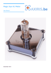
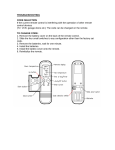
Information Menu
Audio Visualizer
Information
EXIT
►
Information
Screen
User Manual
This menu shows information about the Audio Visualizer.
Information
EXIT
1
2
►
3
1
Exit to the configuration menu.
2
No function.
3
Show the first information screen.
The entry screen.
Information
Screen
1
2
3
1
2
Press any button to advance to the next information
screen.
3
The various information screens. The contents depend on the revision of the system.
Contact Information
Official website: http://www.axiris.eu/
November 2013
12
User Manual
Safety Precautions
Startup Menu
◄► Audio
Do not power on a display module when tubes are damaged or missing.
1
2
►
3
Risk of electrical shock. Do not power on any display module when the casing of one or
more modules is incomplete, broken or taken apart. Keep the modules in a dry place.
Selecting the previous item.
2
Selecting the next item.
3
Go to the next screen.
Select the menu that the system activates after start-up.
Do not take apart the display modules or the control module.
Use the power supply that came with the display module, or use a power supply that's
compliant with the technical specifications of the display module.
Operate the system in a well-ventilated area only and keep it away from flammable
materials. Always clean the system with a dry or very slightly damp cloth. Do not use any
detergents or alcohols. Be careful while touching the tubes, esp. the nozzle at the top.
Power off the system before cleaning. The system must be completely dry when it's
powered on.
Startup Standby
◄► OFF
►
1
2
3
1
Select YES or NO.
2
Select YES or NO.
3
Go to the next screen.
Select whether or not the system starts up in standby mode (sleep mode).
This feature is useful if main power may go down while you keep the system in standby.
If start-up standby mode is ON, and main power goes down and comes back up after a
while, the system will restart and immediately go back to standby.
Technical Information
RGB Animation
WAVE
1
Control Module
1
Power consumption
2.5 W max.
Dimensions
124 mm x 125 mm x 34 mm (W x D x H)
Weight
270 g
2
1
12 VDC, 1000 mA, regulated
Power consumption
10 W max.
DC-connector
5.5 x 2.1 mm
Dimensions
264 mm x 74 mm x 195 mm (W x D x H)
Weight
660 g
and
Cycle through the group of RGB animation types:
WAVE ► SOLID
►
2
Select the next RGB animation.
3
Go to the next screen.
3
Bus Speed
◄► 100 kHz
Power supply
1
Here you can select the default RGB animation. This selection becomes apparent when
you enter the audio menu or the animation menu.
IN-13 Display Module
2
►
3
1
Select the previous value.
2
Select the next value.
3
Go to the next screen.
The communication speed between the main module and the display module is
selectable. Select 160 kHz or higher if you've hooked up two IV-26 display modules. 100
kHz suffices for all other combinations of display modules.
allowed
When you change the bus speed, it'll only take effect when you save the settings and
restart the system.
IV-26 Display Module
Save?
YES
Power supply
12 VDC, 500 mA regulated
Power consumption
5 W max.
DC-connector
5.5 x 2.1 mm
Dimensions
264 mm x 74 mm x 150 mm (W x D x H)
Weight
600 g
2
1
1
and
allowed
NO
2
BACK
3
1
Save all changes to the EEPROM and go back to the first
screen.
2
Discard all changes and go to the next screen.
3
Restart modifying the settings. All changes made so far are
preserved.
When you choose YES, the settings are saved in the EEPROM of the main module.
User Manual
User Manual
11
Burn In Menu
Handling
Burn in
IV-26 IN-13
Do not carry an IN-13 display module or an
IV-26 display module while holding the outer
columns, the tubes, or the horizontal top
latch that secures the tubes.
Right tube 5
◄► 3600
04:25
IN-13 tubes are subjected to a burn-in procedure during the production of the display
module. You should not perform the burn-in procedure yourself. Only after the display
module hasn't been used for a very long time, the tubes may require another burn-in.
Burn in
IV-26 IN-13
1
2
3
1
Start burning in the tubes on the left display. IN-13 only.
2
Start burning in the tubes on the right display. IN-13 only.
3
Exit to the configuration menu.
Always carry an IN-13 display module or an
IV-26 display module while holding the left
side and the right side of the base in your
hands. You can also carry the display module
with the middle of the base.
Control Module
Select the IN-13 display module you want to subject to the burn-in procedure.
1
Right tube 5
◄► 3600
04:25
1
2
Right Display
Decrement the value.
Left Display
3
2
Increment the value.
3
Select the next tube. When the last tube has been handled,
go to the first screen.
Stereo Line Output
Stereo Line Input
Microphone
The timer starts running when a value of 2000 or higher is selected. When the timer
reaches 15:00 the system will automatically reset the value to 600. This measure
prevents a tube from being damaged in case one forgets to select the next tube.
Right Volume
Left Volume
LCD
Reset Button
Settings Menu
Settings
EXIT
Bus Speed
◄► 160 kHz
LCD Contrast
►
Startup Menu
◄► Audio
►
Save?
YES
►
Startup Standby
◄► OFF
►
RGB Animation
WAVE
1
►
Extension Ports[1]
NO
1
2
►
3
1
Exit to the configuration menu.
2
No function.
3
Start modifying settings.
Not used at the moment.
Installation
An Audio Visualizer system consists of a control module and one or two display modules.
Connect each display module with an UTP cable to the corresponding display port.
The entry screen.
10
Menu Buttons
BACK
[1]
Settings
EXIT
USB Port
When a the line input is plugged in, the system visualizes the audio from the line input,
else the system visualizes the audio from the built-in microphone. The audio is outputted
User Manual
User Manual
3
to the stereo line output jack.
Calibration Menu
The system is powered by the display modules.
WARNING!
Calibration
IV-26 IN-13
Use a regulated 12 VDC power supply. If you use an unregulated power supply, it may
damage the display modules.
Right tube 5
◄► 840
Save?
YES
NO
BACK
Each IN-13 tube shoots out differently. The calibration menu offers a method for finetuning the height at which the tubes glow for a specific reference level. The red markers
near to top of the IN-13 tubes may serve as the reference level.
Bootloader
There are two methods for invoking the bootloader.
1. Hold down buttons 1 and 3 while powering up the system. The system will start up in
bootloader mode.
Bootloader
POWER UP
1
2
3
1
2
3
2. When the system is powered up, hold down the RESET button along with buttons 1
and 3. When you release the RESET button, the system will go to bootloader mode.
RESET
1
2
3
During the calibration procedure, you must
adjust each tube's glowing height to the
reference level.
Calibration
IV-26 IN-13
Bootloader
RESET
The red markers may not be aligned perfectly
horizontal. If this is the case, you're advised
to use something different as a means of
reference level, like a ruler, a piece of paper,
or a rubber band that's not too tightly
wrapped around the display's outer columns.
It's preferably to align this means with the
lowest red marker of all tubes in the vertical
direction.
1
1
2
2
3
3
With the bootloader active, you can update the firmware in the control module. Connect
the USB port to a PC for this purpose.
1
Start calibrating the tubes on the left display. IN-13 only.
2
Start calibrating the tubes on the right display. IN-13 only.
3
Exit to the configuration menu.
In the entry screen you can select the display module you want to calibrate.
Right tube 5
◄► 840
1
2
3
Main Menu
1
Decrement the value.
2
Increment the value.
3
Select the next tube. When the last tube has been
calibrated, go to the next screen.
The tubes on the display are calibrated from left (tube 1) to right (tube 8).
Main Menu
◄► Audio
Main Menu
◄► Animation
Main Menu
◄► Audio
1
4
2
3
Main Menu
◄► Demo Mode
1
Select the previous menu.
2
Select the next menu.
3
Enter the selected menu.
Main Menu
◄► Configuration
Save?
YES
NO
1
2
BACK
3
1
Save the calibration values in the display's EEPROM.
2
Discard the calibration values and go back to the first
screen.
3
Resume calibrating the tubes. All values are retained.
You can choose BACK to check the calibration values and to further fine-tune the
calibration of each tube.
When you choose YES, the calibration data is saved in the EEPROM of the IN-13 display.
User Manual
User Manual
9
Configuration Menu
Cfg. Menu
◄► Calibration
Audio Menu
Cfg. Menu
◄► Burn in
Cfg. Menu
◄► Settings
Cfg. Menu
◄► Information
1
2
3
1
Select the previous menu.
2
Select the next menu.
3
Audio
SOLID
►
24
►
Audio
EXIT SLEEP
►
This menu enables audio visualization on the display modules. The system samples the
stereo audio input signal and visualizes the frequency bands on the connected displays.
The display connected to the left port visualizes the left audio channel, the display
connected to the right port visualizes the right audio channel. The audio input signal
comes from the audio input or the built-in microphone.
Cfg. Menu
◄► Main
Cfg. Menu
◄► Calibration
Audio
IV-26 IN-13
Audio
IV-26 IN-13
►
Enter the selected menu.
1
2
3
1
Reinitialize the left display.
2
Reinitialize the right display.
3
Go to the next screen.
This is the entry screen of the audio menu. It shows which display modules are
connected. You can reinitialize a display module by pressing the corresponding button.
1
Audio
SOLID
24
1
2
Cycle through the group of RGB animation types:
WAVE ► SOLID ► SPECTRUM
►
2
Select the next RGB animation.
3
Go to the next screen.
3
Here you can change the RGB animation on the display modules.
The spectrum animation is exclusively available in the audio menu. It animates the RGB
LEDs based on the sampled audio signal.
Audio
EXIT SLEEP
1
2
►
3
1
Exit to the main menu.
2
Put the system in sleep mode. Press any button to wake up.
3
Go to the first screen.
Here you can exit to the main menu, put the system to sleep or go back to the entry
screen.
8
User Manual
User Manual
5
Animation Menu
Animation
IV-26 IN-13
Demo Menu
Animation
WAVE
5
►
Animation
EXIT SLEEP
►
Demo Mode
EXIT
►
When this menu is active, the system shows animations on the connected display
modules. You can change both tube animations and RGB animations.
Animation
IV-26 IN-13
1
2
►
3
1
Select the next animation on the left display.
2
Select the next animation on the right display.
3
Go to the next screen.
1
Animation
WAVE
5
1
1
2
2
Select the next RGB animation.
3
Go to the next screen.
2
3
Run Demo Program
START
►
1
Exit to the main menu.
2
No function.
3
Go to the next screen.
1
Select the previous demo program.
2
Select the next demo program.
2
3
3
Go to the next screen.
Choose one of the available demonstration programs:
Here you can change the RGB animation on the display modules.
1
►
Entry screen.
1
►
3
Choose Program
◄► 1
►
WAVE ► SOLID
3
Animation
EXIT SLEEP
2
►
Cycle through the group of RGB animation types:
►
Can Stop?
◄► YES
The demo menu allows you to run a demonstration program. Such program takes over
control of the buttons and uses the system as if it were a real-life user. A demonstration
program may run definitely and indefinitely.
Demo Mode
EXIT
The entry screen of the animation menu shows which displays are connected. You can
advance to the next animation by presses the display's corresponding button.
Choose Program
◄► 1
►
►
1. Animations Showcase: The program shows tube and RGB animations indefinitely. You
can run this program to show the system unattended in a store or public place.
1
Exit to the main menu.
2
Put the system in sleep mode. Press any button to wake up.
3
Go to the first screen.
Here you can exit to the main menu, put the system to sleep or go back to the entry
screen.
2. Menu Presentation: The program walks through the various menu screens and allows
one to explore or present to an audience the available features and settings. This
program runs definitely and ends up in the entry screen of the demo menu.
Can Stop?
◄► YES
1
2
►
3
1
Select YES or NO.
2
Select YES or NO.
3
Go to the next screen.
Decide whether one may or may not interrupt a running demonstration program. If set to
YES, one can stop the demonstration program by pressing any of the buttons. If NO is
selected, the only way to stop the demonstration program is to power-cycle or reset the
system.
Run Demo Program
START
►
1
2
3
1
Start running the selected demo program.
2
No function.
3
Go to the first screen.
Here you can start the selected demonstration program.
6
User Manual
User Manual
7