1
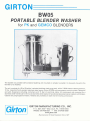
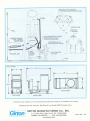
GIRTON PORTABLE WASHER MODEL BW05
1. DESCRIPTION
This system is a portable, self-contained washing unit mounted on casters to enable it to be easily moved
from blender to blender. The operating cycle is entirely automatic with each stage of operation under PLC
control at all times.
2. REGULATIONS, CODES AND STANDARDS
All engineering, design, manufacture and testing conforms to all applicable sections of the latest edition of the
following codes, standards and specifications in effect at the time of order:
ASME-BPE - American Society of Mechanical Engineers
ANSI
- American National Standard Institute
ASTM - American Society for Testing and Materials
OSHA - Occupation Safety and Health Administration
NEMA - National Electrical Manufacturers Associates
NEC
- National Electrical Code
cGMP - Current Good Manufacturing Practices (CFR Title 21 parts 210 and 211)
NFPA - National Fire Protection Association
3. DIMENSIONS AND WEIGHT
3.1.
Overall Height: 54”
3.2.
Overall Width: 31”
3.3.
Overall Depth: 70”
3.4.
Operational Weight: 650 lbs.
4. CONSTRUCTION
4.1.
Material Type and Finish:
4.1.1.
4.1.2.
4.1.3.
4.1.4.
4.1.5.
4.2.
Washer Frame: 14 gauge, T-304
Interior Finish: mill finish (2B)
Exterior Finish: 35Ra or better
T-316L stainless steel
35Ra or better 15Ra
Washer Tank: 14 gauge, T-304 T-316L stainless steel
Interior Finish: mill finish (2B) 35Ra or better 15Ra
Exterior Finish: 35Ra or better
8.5Ra
8.5Ra
Insulation Jacket: 20 gauge, T-304 stainless steel,
Exterior Finish: 35Ra or better
Electric Heat: Incalloy elements
Compressed Air:
Tubing Poly-flo
T-304 stainless steel.
4.1.6.
Potable Water Supply Ball Valves: T-304 stainless steel
4.1.7.
Sanitary valves: T-316L stainless steel diaphragm valves
Interior Finish: 35Ra or better Electro-polished to 15 Ra finish
4.1.8.
Tri-Clamp Clamps: T-304 stainless steel
4.1.9.
Fasteners: T-304 stainless steel
Unit Design:
The equipment is designed to be shipped and installed as a single unit. Some parts may be
removed prior to shipping (i.e., pumps) to decrease the possibility of damages during shipping. The
maximum crate size will be approximately ____” x ____” x ____” with an estimated weight of
______lbs.
4.3.
All internal corners have a minimum 5/16” radius.
4.4.
See enclosed Girton’s Welding Specification for information on current in-house welding
procedures.
4.5.
All visible welds on the exterior of the washer tank are thoroughly cleaned. All welds on the interior
of the washer tank are ground and polished.
4.6.
The cabinet interior is constructed to permit free draining and designed not to retain any of the
process solutions.
4.7.
The washer tank capacity is approximately 35-gallons of water, assuring effective cleaning and
economy of operation. Level control is by means of a stainless steel float switch, which is tied into
the washer control system.
4.8.
The washer drains by gravity. An air activated two-way ball valve directs the discharge to the drain,
resulting in a quick drain time.
4.9.
The unit is insulated with fiberglass and covered with a full jacket. This insulation package greatly
reduces radiated heat loss from the washer making it more economical to operate and affords more
comfort for the operators.
4.10.
The wash tank is provided with electric immersion heaters controlled by the control system
(adjustable) to maintain the wash/rinse solutions at a preset temperature.
4.11.
Pumps:
4.11.1.
Recirculating wash/rinse pump is a T-316 stainless steel horizontal centrifugal type
unit, powered by a 10 Hp motor.
4.11.2.
Sanitary recirculating wash/rinse pump is a T-316 stainless steel horizontal
centrifugal type unit, powered by a 15 Hp motor.
4.12.
Potable water supply ball valves are threaded connections.
4.13.
All ancillary valves and equipment are positioned within the confines of the cart.
4.14.
Sanitary valves have an EPDM diaphragm and tri-clamp ends. Two weep holes are located in the
bonnet.
4.15.
Tri-clamp connection use EPDM gaskets and are connected by means of heavy-duty clamps with
wing nuts.
4.16.
Seals, gaskets, and bearings are compatible with the temperatures and concentrations of cleaning
agents to be used. Customer will supply information on chemicals to be used.
4.17.
A compressed air system is supplied with a filter regulator.
4.18.
Handles shall be provided on each end for moving the unit from location to location.
4.19.
The washer is piped and wired for single service connection for each utility requirement.
5. CONTROLS AND OPERATION
5.1.
The control system incorporates an Allen Bradley Compact Logix ®PLC. This provides 512K of
memory with Ethernet communication ability. The processor is aware of and controls all items on the
washer. I/O cards are selected to match the control voltage. An isolated relay card is used to control
high current draw items or items not operable at the control voltage. Analog cards are set to accept 4
- 20 mA inputs, unless otherwise noted.
5.2.
The operator-machine consists of an Allen Bradley Color Panelview Plus 600, which incorporates a
touch screen for operator control. This allows the user with proper password level to access all
parameters of a wash recipe. All alarms are shown on the display, as well as announced audibly.
5.3.
The washer is provided with the ability to use a printer to record operation reports. The customer
should mount the printer close to the washer. Communication to the printer is RS232C so the
maximum recommended distance from the washer is 50 ft. The report contains the following data:
machine identification, operator, date and time, step name with time, temperature (min-max), etc.
5.4.
A typical treatment cycle is defined as follows:
Pre-Wash – Recirculated
Wash – Recirculated
Rinse – Recirculated
Rinse – Recirculated
Rinse – Recirculated
5.5.
A total of 16 programs can be stored in the PLC. Each program can be altered or developed from the
OIT. Access to change or develop the programs is password protected.
5.6.
Girton provides three levels of password protection to the control system:
Operator Level – access to selection of existing programs only
Maintenance Level – access to all maintenance screens
Engineering Level – access to all levels. Allows changes to be made to existing programs and
new programs to be developed.
5.7.
Girton’s control system provides the ability to alarm on abnormal conditions. The washer has
alarms based on each I/O point failure. This provides a comprehensive way of determining a device
failure or process deviation. In general, all analog inputs to the system will have low and high alarm
points settable by the customer. Also, all safety devices, such as door switches or emergency stop
buttons, have alarms associated with them.
5.8.
The washer is equipped with Emergency Stop switches located at critical points on the machine. All
doors are equipped with limit switches wired directly to the output voltage. Opening any door will
disconnect voltage from output cards thereby shutting down the system. These switches are also
wired as inputs to the PLC so that an alarm may be generated. All services are equipped with failclosed-valves.
5.9.
See enclosed Girton's Electrical Specification for information on wiring, conduit, tagging,
instrument installation and color-coding.
5.10.
Noise level as measured from 3 ft. from the washer will be a minimum of 85 dBa.
6. DOCUMENTATION
6.1.
3 Hard copies and 1 electronic copy of Girton Documentation Package. Validation requirements
and considerations are playing an increasingly major role in the purchase of new equipment or
systems. Validation requires documented evidence that the equipment or system will reliably perform
in a manner consistent with the original design specifications. Generation of this documentation
needs to be considered at the inception of the project and implemented throughout the design and
manufacturing stages of the equipment. In most instances, the equipment vendor is the most
qualified party to generate the majority of the required documentation.
The documentation provided by Girton Manufacturing Co., Inc. is designed to be a complete package
including all data and checklists necessary to qualify the installation and operation of the equipment
and/or system. All equipment built by Girton is completely factory assembled and tested. The
documentation is used to perform Factory Acceptance Testing; witnessed and approved by the
customer. All tests necessary for Installation and Operation Qualification of the equipment are
performed on the equipment prior to its arrival on the job-site. Any modifications or additions required
to qualify the equipment can be made at the factory prior to shipment.
This index lists all documentation supplied by Girton Manufacturing Co., Inc.
1
DRAWINGS
DRAWINGS
Installation/General Arrangement
P&ID – Piping and Instrumentation Drawing
ELECTRICAL SCHEMATICS & PANEL DRAWINGS
ELECTRICAL SCHEMATICS - 3 Phase Wiring Diagrams, Control Wiring Diagrams, I/O Wiring
Diagrams
PANEL LAYOUTS - PLC Panel Layout, Motor Starter Panel Layout
AIR PIPING SCHEMATICS
2
EQUIPMENT DATA
INSTRUMENT LIST
Tag numbers, manufacturer, model number, serial number, and description for all instruments
installed on the washer.
MECHANICAL EQUIPMENT LIST
Component description, manufacturer, model number, and materials of construction.
CONTROL SYSTEM COMPONENT LIST
Tag numbers, manufacturer, model number, serial number, and description for all control system
components installed on the washer.
EQUIPMENT LUBRICATION LIST
List of lubricants used to maintain the washer.
USER MANUAL
Instructions for operating the equipment including loading, unloading, control system operation,
and safety precautions. Maintenance schedules and repair procedures for all equipment and
instruments.
CALIBRATION AND CERTIFICATION
Calibration sheets, certifications and procedures for calibrating all critical instruments provided by
Girton.
(SHORT TERM) PRICED SPARE PARTS LIST
PRICED SPARE PARTS LIST
Listing of replacement parts and their corresponding order numbers. Instructions on information
required when ordering replacement parts.
COMPONENT CATALOG BROCHURES
Manufacturer’s catalog information concerning installation, operation, and maintenance
procedures for all purchased mechanical equipment and instruments.
CUSTOMER SERVICE POLICY
Tells about the warranty, damages, replacement parts, returned merchandise, field service,
cancellation, and special equipment.
3
SOFTWARE DATA
QUALITY AND PROJECT PLAN
Defines the quality and project objectives for the washer and its automated control system.
FUNCTIONAL SPECIFICATION
Outlines functional requirements for the equipment.
HMI & PLC DESIGN SPECIFICATIONS
This document defines the hardware and software specifications for the washer and its
component parts. The purpose of this document is to describe the complete operation of the
automated process control system for the washer.
PROGRAMS ON CD
RS VIEW
Reports generated by the display software, which define screen elements and tag numbers
corresponding to PLC addresses.
PLC RS LOGIX 500 PROJECT REPORT
Annotated listing of all code used to implement the software design.
4
FACTORY ACCEPTANCE TEST
ABXXX FAT Instructions / Reference
ABXXX Section 02 FAT Approval Drawing Review Test
ABXXX Section 03 FAT Instrument Tests
ABXXX Section 04 FAT Mechanical Equipment Tests
ABXXX Section 05 FAT Electrical Tests
ABXXX Section 06 FAT Utility Tests
ABXXX Section 07 FAT Control System Hardware Tests
ABXXX Section 08 FAT Control System Software Tests
ABXXX Section 09 FAT Calibration Tests
ABXXX Section 10 FAT HMI Tests
ABXXX Section 11 FAT Operation Tests
ABXXX Section 12 FAT Alarm Tests
ABXXX Section 13 FAT Power Failure Tests
ABXXX Section 14 FAT Summary Report Tests
ABXXX Section 15 FAT Project Tests
ABXXX FAT Signature Log
ABXXX FAT Instrument Log
ABXXX FAT Exception Log
ABXXX FAT Test Progress Sheet
ABXXX FAT Exception Form
5
PASSIVATION & PUNCHLIST REPORTS
Passivation Procedure
Passivation Report
Completed Punchlist
VOLUME 3 OF 4
6
SITE ACCEPTANCE TEST
ABXXX SAT Instructions / Reference
ABXXX Section 02 SAT Approval Drawing Review Test
ABXXX Section 03 SAT Instrument Tests
ABXXX Section 04 SAT Mechanical Equipment Tests
ABXXX Section 05 SAT Electrical Tests
ABXXX Section 06 SAT Utility Tests
ABXXX Section 07 SAT Control System Hardware Tests
ABXXX Section 08 SAT Control System Software Tests
ABXXX Section 09 SAT Calibration Tests
ABXXX Section 10 SAT HMI Tests
ABXXX Section 11 SAT Operation Tests
ABXXX Section 12 SAT Alarm Tests
ABXXX Section 13 SAT Power Failure Tests
ABXXX Section 14 SAT Summary Report Tests
ABXXX Section 15 FAT Project Tests
ABXXX SAT Signature Log
ABXXX SAT Instrument Log
ABXXX SAT Exception Log
ABXXX SAT Test Progress Sheet
ABXXX SAT Exception Form
7
WELDING
Procedure Qualification Record (PQR)
Weld Procedure Specifications (WPS)
Welding Procedure Qualifications (WPQ)
Weld Inspector Qualifications
Weld Logs and Weld Maps.
8
CERTIFICATIONS
Material Certifications sent with raw materials and some instruments ordered specifically for this
project
Work Order Trace Report
Material Test Reports
Certificates of Conformance/Compliance
7. SERVICE REQUIREMENTS
7.1.
Electrical: 3 phase, 60 cycle, 208 230 460 volt, _____ amperes.
(Fused disconnect to be provided and remote mounted by others.)
7.2.
Hot Water: 180°F. Recommended minimum rate of flow of 20 gallons per minute. 1-1/2” tri-clamp
connection to the machine. 140-gallon consumption/cycle.
7.3.
Final Rinse: (D.I., WFI, etc.) 180°F minimum flow rate 20 gpm at 30 PSI. 1-1/2" tri-clamp
connection.
7.4.
Drain: 1" NPT from the machine to the drain.
7.5.
7.6.
Sprayhead Connections: 1” tri-clamp, quantity (3)
Compressed Air: 1/4" NPT connection, 90-PSI minimum, 5 CFM.
8. WARRANTY
8.1.
Girton Manufacturing Co., Inc. warrants equipment of original manufacture against defect in
workmanship and material for a period of one year from date of shipment. Provided; however, the
equipment has been operated under normal working conditions for such said equipment, that it has
been properly serviced and cared for, and that no adjustments have been made by unauthorized
personnel that could adversely affect the operation or life of the equipment.
Girton Manufacturing Co., Inc. will replace or repair defective merchandise at its plant, FOB Millville,
PA, if after inspection; the equipment or components that Girton manufactured are defective.
Girton Manufacturing Co., Inc. extends to its customers on all purchased components parts, the
warranty of the supplier of such said parts.
No expense, liability, or responsibility will be assumed by Girton for repairs outside Girton’s factory,
without written authority from Girton Manufacturing Co., Inc.
The foregoing warranty excludes all other warranties, guaranties, and/or representations; whether
expressed, implies, or oral, INCLUDING, BUT NOT LIMITED TO, ALL CONDITIONS AND
EXCLUSIONS OF IMPLIED WARRANTY OF MERCHANTABILITY AND OR FITNESS FOR THE
PURPOSE, and the warrantor’s liability for any direct damage arising from a legally proven breach of
the warranty hereby extended is limited to the customer’s invoice cost of the goods warranted.
8.2.
DISCLAIMER OF CONSEQUENTIAL DAMAGES LIABILITY - Girton Manufacturing Co., Inc. shall not
be liable for consequential damages of any kind, including incidental labor or other costs.
9. CANCELLATION
9.1.
Any order on which work had been started may be cancelled only be consent of Girton Manufacturing
Co., Inc. and by agreement on the part of the purchaser to cover whatever cost has been incurred, if
any, to the date of the cancellation, including engineering, administrative, material purchases, labor,
and overhead expended.
10. CUSTOMER TO WITNESS PRELIMINARY FACTORY ACCEPTANCE TEST (FAT)
10.1.
Customer may witness preliminary testing performed at Girton Manufacturing Co., Inc. prior to
shipment to customer’s facility.
Customer will supply adequate samples of the items being washed. If customer specifies a particular
chemical to be used, they shall supply it, complete with a MSDS Report. Customer shall be
responsible for disposal or removal of excess chemical from premises.
10.2.
Factory Acceptance Test (FAT) – Girton Manufacturing Co., Inc. will provide the necessary
personnel for a maximum of 3 days to assist with the Factory Acceptance Test (FAT). The Girton
Factory Technicians will work with the customer’s personnel in verifying the washer is built and
operates according to the FAT documentation.
11. DOCUMENTS
11.1.
___ # sets of Approval Documents will be provided to the Customer in ___ days weeks after
receipt of order. Production work will not be initiated until these drawings are returned to Girton
Manufacturing Co., Inc. with the appropriate signatures of the customer.
12. INSTALLATION
12.1.
Installation will be done by others.
Supervision of installation by Girtons - Girton Manufacturing Co., Inc. will provide a technician
for _____ (# of days) who will work with the customer’s in-house personnel or with an outside
contractor. The technician(s) will provide instructions for all phases of re-assembly including moving
the equipment, leveling, re-assembly, and connection to utilities for an additional fee.
Set-in-place installation by Girtons Girton Manufacturing Co., Inc. will provide the necessary non-union labor to re-assemble the
equipment and make it ready for utility connections at the customer’s site. The customer will be
responsible for receiving the equipment, unloading and moving it to the area where it is to be installed
prior to Girton’s arrival and for connecting the utilities.
Girton Manufacturing Co., Inc. will provide the necessary union labor to re-assemble the
equipment and make it ready for utility connections at the customer’s site. The customer will be
responsible for receiving the equipment, unloading and moving it to the area where it is to be installed
prior to Girton’s arrival and for connecting the utilities.
Complete installation by Girtons
Girton Manufacturing Co., Inc. will provide the necessary non-union labor and material to
perform a complete installation of the equipment. This includes receiving the equipment at the
customer’s site, unloading, uncrating, move in place, re-assembly and connection to existing utilities.
The utilities must be within 4 feet from the equipment.
Girton Manufacturing Co., Inc. will provide the necessary union labor and material to perform a
complete installation of the equipment. This includes receiving the equipment at the customer’s site,
unloading, uncrating, move in place, re-assembly and connection to existing utilities. The utilities
must be within 4 feet from the equipment.
13. TERMS AND CONDITIONS
13.1.
Payment Terms:
Please consult factory.
13.2.
The 6% PA sales tax will be assessed on all sales. If you believe the products covered by this
proposal are exempt from this tax, please send to Girton Manufacturing Co., Inc. your PA sales tax
exemption certificate.
14. SHIPPING
14.1.
15.
Freight terms:
Collect
Prepaid by customer
Third Party Billing
and add to Invoice
14.2.
Shipment will be provided by
customer.
transportation arranged by Girton Manufacturing Co., Inc.
14.3.
Shipment from Millville, PA ___ to ___ weeks, after receipt of signed Documents by Girton
Manufacturing Co., Inc.
TOTAL COST PER SPECIFICATION, CONSULT FACTORY
16. OPTIONS
16.1.
The Human Machine Interface (HMI), mounted on the washer, consists of a PLC based display,
which will be programmed using RSView SE software, which incorporates a touch screen for operator
control and monitoring. This allows the user with proper password level to access all parameters of a
wash recipe. All alarms are shown on the display, as well as announced audibly. Use of this system
complies with CFR21 Part 11.
16.2.
Sprayhead adapters must be installed in each blender wall or cover to accept the sprayhead
assemblies. Sprayhead Adapters will include the weld-in adapter, 3" tri-clamp, end cap, and clamp.
(Normally three adapters are required for each V-Blender; Double Cones require a minimum of one in
the cover.)
16.3.
Sprayhead assemblies include the following 360° sprayball, three feet of pipe with tri-clamp fitting
for connection to hose, 3" tri-clamp for connection to sprayhead adapter. The length of insertion into
the blender can be adjusted by setting the 3" tri-clamp at the desired distance. The sprayhead
assemblies are removed during normal operation of the blender.
16.4.
T-316L construction on all wetted surfaces with the exception of distribution hoses.
16.5.
Process piping and purified final rinse will be electro polished to a 15Ra finish on the interior.
OD will be 35Ra or better finish.
16.6.
Interior finish to be a 35Ra or better finish.
16.7.
The discharge pressure of the main circulation pump is monitored using a sanitary pressure
transmitter. This pressure is recorded and alarmed by the control. The diaphragm of the sensor is
attached in the wash pump discharge line using a tri-clamp connection. Girton'
s standard range for
measuring pump pressure is 0 to 100 psi. Girton'
s preferred vendor is Rosemount for the instrument.
16.8.
All compressed air lines are T-304 stainless steel with Swagelok compression split ferrule type
fittings.
16.9.
A sample port in the recirculation sump allows sampling of the water from the face of the washer.
The sample port is attach via tri-clamp with connecting piping to have sufficient pitch in order to drain
back into the washer recirculation tank, thus eliminating the possibility of dead legs.
16.10. A drain tempering system cools the process wash and rinse solutions from 180° F to 140° F prior to
entering the customer’s drain. This system consists of a temperature control with a probe located in
drain line for on-off control of cold water supply valve.
16.11. The conductivity of any wash solution where a reagent is added is monitored, recorded and, if
needed, alarmed by the control. A sensor is attached either in the wash pump discharge or directly
into the sump. Both are inserted into a sanitary tri-clamp connection. Girton'
s standard range for
measuring wash solution conductivity is 0 to 100 milli-siemens.
16.12. The conductivity of the final rinse with the customer'
s designated water will be monitored, recorded
and, if needed, alarmed by the control. The sensor is attached in or near the drain line with a sanitary
tri-clamp connection. Girton'
s standard range for measuring final rinse conductivity is 0 to 100 microsiemens.
16.13. Automatic detergent dispenser is provided with the control system. One (1) peristaltic pump with
120VAC motors is used to charge the wash solution with the desired reagent. The customer sets the
amount of time that each dispenser will run for the wash cycle.
16.14. For each reagent reservoir, Girton supplies a level monitor. The monitor will consist of an ultrasonic
sensor that will switch a PLC input when the reagent reaches the specified level. The control can
then either trigger an alarm or a status message based on the input. The sensor has threads
allowing it to be mounted into the lid of the customer’s detergent reservoir.
16.15. A remote mounted Epson LX300 printer will be provided so that a printed record of each cycle can
be obtained.
16.16. The washer is specified to be in a Class I Division 2 Group D area. All wiring, conduit, instruments,
and other devices conform to the NEC and NFPA regulations for the class and division of the washer.
If required, purged enclosures will be provided as well as explosion resistant conduit.
16.17. All conduit on the machine are PVC coated rigid. Fittings and conduits are PVC coated as well.
Liquid tight flexible conduit is used to connect the washer'
s devices. Lengths of flexible conduit do
not exceed 3 feet. All marks on conduit are painted with PVC paint. All conduit installation meets the
current NEC requirements.
16.18. All controls are rated at 24VDC, if possible. Items not able to operate at 24VDC have a control relay
that will provide contacts usable at 120VAC.
16.19. Each motor under control have a locally mounted HAND-OFF-AUTO switch and a “Run” light. In
HAND position, the motor runs; in OFF position, the motor stops; in AUTO position, the motor is
under PLC control.
16.20. Additional copies of our Documentation Package (reference item # _____ of this specification)
may be purchased.
16.21. Optional Documentation:
16.21.1. Surface Finish Map and Certificate of Compliance
16.21.2. Slope Map of Process Contact Tubing and Certificate of Compliance
16.21.3. Video Weld Logs
16.21.4. Sound Level Certificate of Conformance
16.22. Supervision of installation (YSOFI) – Girton Manufacturing Co, Inc. will provide ONE Qualified
Technician for ___ (# of days) contiguous* on-site days to Supervise and Direct Customer Personnel,
Contractors or Subcontractors in all phases of Installation. This includes oversight of Uncrating and
(1)
(2)
Moving the Equipment into a prepared Wash Room, Leveling and Reassembly, Utility and
(3)
Additional Support Systems Connections. Supervision of Unloading the Shipping Truck will be
performed only if delivery occurs during the scheduled timeframe.
Supervision of Installation (SofI) does not include Sub-Contracting, Equipment or Tools or Tool
Rental, Dumpsters and/or Trash Disposal, Multiple Trips from our Factory (except at our discretion
and as deemed necessary by our Technical Service Manager), Additional Site Preparation, Materials
for Floor Protection, Integration Materials or Fabrication (other than Modular Walls, Fascia Panels,
and items purchased from Girton Mfg. as an option), Equipment Start Up, Training of Personnel or
Assisting with SAT or Validation Documentation.
The Customer will be responsible for all facets of installation not specifically included above.
Equipment Start Up, Training of Personnel, Assisting with SAT or Validation Documentation may be
purchased from Girton separately.
A Field Report will be submitted to the Customer within one week of completion of the installation.
Supervision of Installation is a quoted option and valid as part of the original equipment order.
Service ordered after the original equipment order date will require a re-quote. Travel expenses are
included in the first day billing. Additional contiguous days may be purchased for a flat fee of
$_____.00 per day, but should be purchased prior to the first on-site day, if possible. This information
is based on non-union labor. Special provisions and prices apply when union labor and/or prevailing
wages are required. Contact your Sales Rep for further details.
16.23. Set-in-place Installation (YSIP) - Girton Manufacturing Co, Inc. will provide Qualified Technicians for
(1)
___ (# of days) contiguous* on-site days to Unload and Uncrate, Move the equipment to a prepared
location, Reassemble and Level the Equipment. Girton Manufacturing Co, Inc. will provide all
Personnel, Material, Tools and Equipment to perform the task, including Fork Trucks, Dumpsters,
Welders, Hand Tools, Floor Protection and Trash Elimination.
(2)
Set-In-Place Installation (SIP) does not include Utility Connections, Connection of Additional
(3)
Support Systems , Multiple Trips from our Factory (except at our discretion and as deemed
necessary by our Technical Service Manager), Additional Site Preparation, Integration Materials or
Fabrication (other than Modular Walls, Fascia Panels, etc., purchased from Girton Mfg. as an option),
Equipment Start Up, Training of Personnel or Assisting with SAT or Validation Documentation.
The Customer will be responsible for all facets of installation not specifically included above.
Equipment Start Up, Training of Personnel, Assisting with SAT or Validation Documentation may be
purchased from Girton separately.
A Field Report will be submitted to the Customer within one week of completion of the installation.
Set-In-Place Installation is a quoted option and valid as part of the original equipment order. Service
ordered after the original equipment order date will require a re-quote. Travel expenses are included
in the first day billing. Additional contiguous days may be purchased for a flat fee of $_____.00 per 8
Hr. man-day, but should be purchased prior to the first on-site day, if possible.
This information is based on non-union labor. Special provisions and prices apply when union labor
and/or prevailing wages are required. Contact your Sales Rep for further details.
16.24. Complete Installation (YINSTALL) - Girton Manufacturing Co, Inc. will provide Qualified Technicians
(1)
for ___ (# of days) contiguous* on-site days to Unload, Uncrate, Move the equipment to a prepared
(2)
location, Reassemble, Level the Equipment and Connect Utilities to existing stubs within 6’ of the
machine. Girton Manufacturing Co, Inc. will provide all Personnel, Material, Tools and Equipment to
perform the task, including Fork Trucks, Dumpsters, Welders, Hand Tools, Floor Protection and Trash
Elimination. Test and Demonstration (see below) is part of this option. If this cannot be completed
contiguously (due to unavailable utilities, Customer personnel availability, etc.), a return trip must be
scheduled and additional travel expenses will apply.
Complete Installation (CI) does not include Multiple Trips from our Factory (except at our discretion
and as deemed necessary by our Manager), Additional Site Preparation, Connection of Additional
(3)
Support Systems , Integration Materials or Fabrication (other than Modular Walls, Fascia Panels,
etc., purchased from Girton Mfg. as an option), Equipment Start Up, Training of Personnel or
Assisting with SAT or Validation Documentation.
The Customer will be responsible for all facets of installation not specifically included above.
Equipment Start Up, Training of Personnel, Assisting with SAT or Validation Documentation may be
purchased from Girton separately.
A Field Report will be submitted to the Customer within one week of completion of the installation.
Complete Installation is a quoted option and valid as part of the original equipment order. Service
ordered after the original equipment order date will require a re-quote. Travel expenses are included
in the first day billing. Additional contiguous days may be purchased for a flat fee of $____.00 per 8
Hr. man-day, but should be purchased prior to the first on-site day, if possible.
This information is based on non-union labor. Special provisions and prices apply when union labor
and/or prevailing wages are required. Contact your Sales Rep for further details.
16.25. Test and Demonstration (YTD) - Girton Manufacturing Co, Inc. will provide ONE Qualified
Technician for ___ (# of days) contiguous* on-site days to perform Start Up Testing, such as verifying
utility connections and capacities, electrical supply voltage and amperage, motor rotations,
(4)
completeness of assembly, missing components, etc., on fully installed equipment. The Technician
will make normal equipment adjustments and test operation against factory standards. Upon
completion of satisfactory testing, the Technician will demonstrate all phases of the use and operation
of the equipment to any interested parties, provided sufficient time is allotted. We recommend that
three to four hours be dedicated for effective demonstration. We highly recommend that at least one
User of each level of access (Operator, Maintenance, Supervisor/Engineering, Administrative) be
present for the demonstration. Demonstration must not be confused with training; it is NOT a
substitute for a complete and formal training session, ‘Demonstration’ is informal, with the Technician
covering the highlights of the equipment and operation and hazard awareness, and answering
questions from interested parties. No handout sheets or post-training testing is given.
Test and Demonstration (T&D) does not include mechanical reassembly or completion of wiring or
pneumatics (on-skid or otherwise), any function that is normally part of the three Installation options
described above, Multiple Trips from our Factory (except at our discretion and as deemed necessary
by our Technical Service Manager), Additional Site Preparation, or Assisting with SAT or Validation
Documentation.
The Customer will be responsible for all facets of installation not specifically included above.
Supervision of Installation, Set in Place Installation, Complete Installation, Training of Personnel,
Assisting with SAT or Validation Documentation may be purchased from Girton separately.
A Field Report and a copy of an Attendance Record for the demonstration will be submitted to the
Customer within one week from the end of the visit.
Test and Demonstration is a quoted option and valid as part of the original equipment order. Service
ordered after the original equipment order date will require a re-quote. Travel expenses are included
in the first day billing. Additional contiguous days may be purchased for a flat fee of $____.00 per 8
Hr. man-day, but should be purchased prior to the first on-site day, if possible.
This information is based on non-union labor. Special provisions and prices apply when union labor
and/or prevailing wages are required. Contact your Sales Rep for further details.
16.26. Start Up (YSTART) - Girton Manufacturing Co, Inc. will provide ONE Qualified Technician for ___ (#
of days) contiguous* on-site days to perform Start Up Testing, such as verifying utility connections
and capacities, electrical supply voltage and amperage, motor rotations, completeness of assembly,
(4)
missing components, etc., on fully installed equipment. The Technician will make normal equipment
adjustments and test operation against factory standards. Start Up does not include mechanical
reassembly or completion of wiring or pneumatics (on-skid or otherwise), any function that is normally
part of the three Installation options described above, Multiple Trips from our Factory (except at our
discretion and as deemed necessary by our Technical Service Manager), Additional Site Preparation,
or Assisting with SAT or Validation Documentation.
The Customer will be responsible for all facets of installation not specifically included above.
Supervision of Installation, Set in Place Installation, Complete Installation, Training of Personnel,
Assisting with SAT or Validation Documentation may be purchased from Girton separately.
A Field Report will be submitted to the Customer within one week from the end of the visit.
Start Up is a quoted option and valid as part of the original equipment order. Service ordered after
the original equipment order date will require a re-quote. Travel expenses are included in the first day
billing. Additional contiguous days may be purchased for a flat fee of $_____.00 per 8 Hr. man-day,
but should be purchased prior to the first on-site day, if possible. This information is based on nonunion labor. Special provisions and prices apply when union labor and/or prevailing wages are
required. Contact your Sales Rep for further details.
16.27. Training (YTR) - Girton Manufacturing Co, Inc. will provide ONE Qualified Technician for ___ (# of
days) contiguous* on-site days to formally and thoroughly provide in-depth training to Operators,
Maintenance Technicians, Engineering and Administrative Level Personnel. Our Technician will
provide a combination of classroom and hands-on field training. A ‘Question and Answer’ period is
encouraged.
16.27.1. Topics covered are:
Hazard Awareness,
Alarms and the causes of and responses to them,
Routine Operation,
Routine Maintenance and Trouble Shooting,
Set Up, Management and Modification of Recipes (Cycles),
User Management (Administration).
16.27.2. Training (TRN) covers the full range of access and use:
16.27.2.1. ‘Operator’ level training covers the daily operation and maintenance, and is the shortest
and most basic training.
16.27.2.2. ‘Maintenance’ level training includes full Operator training and adds the extensive
maintenance diagnostic capabilities available through the HMI, and PM requirements.
16.27.2.3. ‘Engineering’ level training will include condensed Operator and Maintenance coverage
and adds in-depth Recipe (Cycle) Generation and Management and Recipe and Alarm Set
Points. Engineering training is typically restricted to those individuals responsible for control of
validated operation.
16.27.2.4. ‘Administrator’ level training will have condensed coverage for all levels of use, but will
focus primarily on User Administration and Security. At this level, Users Names and
Passwords are assigned and Levels of Access Controlled.
Whenever possible, a computer presentation will be shown and pertinent hand out sheets
will be distributed. An Attendance Roster and post-training Retention Test will be given and
copies will be provided to the Customer.
Training is a quoted option and valid as part of the original equipment order. Service
ordered after the original equipment order date will require a re-quote. Travel expenses are
included in the first day billing. Additional contiguous days may be purchased for a flat fee
of $______.00 per day, but should be purchased prior to the first on-site day, if possible.
This information is based on non-union labor. Special provisions and prices apply when
union labor and/or prevailing wages are required. Contact your Sales Rep for further
details.
16.28. Site Acceptance Testing Assistance (YSAT) - Girton Manufacturing Co, Inc. will provide ONE
Qualified Technician for ___ (# of days) contiguous* on-site days to assist the Customer’s Validation
(4)
Group(s) with IQ/OQ of fully installed and running equipment. Girton Mfg. will provide an SAT
Template based on the factory test documents and appropriate programming software and test
instruments necessary to duplicate the factory tests. Girton Technicians will assist the Customer by
providing clarification of test procedures and test results, and through our experience with the PLC
and HMI Programming. Sample SAT documents are typically submitted to the Customer for early
review. Machine specific documents shall be submitted to the Customer a minimum of two weeks
prior to SAT.
Girton Technicians will not be responsible for completing partial installations, test document revisions
or test completion.
A Field Report will be submitted to the Customer within one week of completion of the SAT.
Site Acceptance Test is a quoted option and valid as part of the original equipment order. Service
ordered after the original equipment order date will require a re-quote. Travel expenses are included
in the first day billing. Additional contiguous days may be purchased for a flat fee of $______.00 per
day, but should be purchased prior to the first on-site day, if possible. This information is based on
non-union labor. Special provisions and prices apply when union labor and/or prevailing wages are
required. Contact your Sales Rep for further details.
16.29. Notes:
16.29.1.
(1)
16.29.2.
(2)
16.29.3.
(3)
16.29.4.
(4)
“Prepared” site is defined as one at which the building is enclosed, the floor and floor
coatings are complete and where Girton personnel can work reasonably unhindered.
(2)
Electricity (for tools) must be available. It is preferred, but not mandatory, that utilities are
complete and available.
“Utilities” are defined as Potable Water (Hot and/or Cold), Steam, Condensate,
Ventilation, Electrical, Compressed and/or Instrument Air, and Drains. “Utilities” does not
include Purified (DI, WRO, WFI, etc.) water sources that require high-purity pipe welding,
remote Detergent systems or controls, Chiller/Glycol system piping, Facility Control or Data
Systems, networked or otherwise.
“Additional Support Systems” are defined as Purified Water (DI, WRO, WFI, etc.), Chiller
systems, Detergent Systems, Combustible Liquids or Gas, and Breathing Air. Connection
of Additional Support Systems is always the responsibility of the Purchaser.
“Fully Installed” is defined as the equipment being in-place and leveled, and connected
to all utilities and additional support systems. Integration with building fabric is not required.
* Excluding Saturdays, Sundays and/or Holidays, unless prearranged.
GIRTON MODEL BW05 VENDOR LIST
COMPONENT
VENDOR
Controller
Allen Bradley
Limit Switches
Allen Bradley
Temperature Transmitter
Burns
Level Switch
Madison Inc.
Transformer
Square D
Motor Starters
Square D
Terminal Strip
Square D
Fuses and Fuse Holder
Ferraz Shawmutt
Recirculation Pump
Ampco
Sanitary Recirculation Pump
Ampco
Ball Valves - Pneumatic Actuators
Duravalve
Compressed Air Filter Regulator
ASCO
Solenoid Valve (For Pneumatic Actuators)
SMC
Sanitary Diaphragm Valve
ITT
Disconnect Switch
Square D
Emergency Stop Switch
Allen Bradley
Electric Heating Elements
Indeeco
A. Electric Contractors
Allen Bradley
OPTIONS
Door Interlock
Indicating Pressure Transmitter
Rosemount or Equal
Stainless Steel Compressed Air Fittings
Swagelok
Sample Port
Tri Clover
Drain Tempering System
A. Cold Water Control Valve
Duravalve
B. Manual Throttling Valve
Duravalve
Conductivity Sensors
Thornton
Detergent Dispenser
Knight Equipment Co.
Chemical Container Level Sensors
Carlo Gavazzi