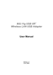
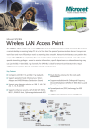
1
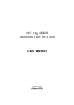
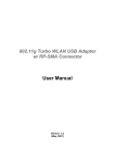
User’s Manual Wireless LAN USB Adapter Model No.: SP907GK http://www.micronet.info CONTENTS 1 INTRODUCTION ..........................................................................................1 1.1 FEATURES.............................................................................................2 1.2 PACKAGE CONTENTS ...........................................................................2 2 INSTALLATION ...........................................................................................3 3 CONFIGURATION AND MANAGEMENT ......................................................8 3.1 AD-HOC MODE ......................................................................................8 To use this adapter in Ad-Hoc Mode.............................................................................. 8 3.2 INFRASTRUCTURE MODE .....................................................................9 To use this adapter in Infrastructure Mode................................................................... 10 4 INTRODUCTION TO THE WIRELESS LAN UTILITY................................... 11 4.1 STARTING THE WIRELESS LAN UTILITY............................................. 11 4.1.1 GENERAL ....................................................................................... 11 4.1.2 PROFILE ......................................................................................... 12 4.1.3 CONFIGURE THE PROFILE ............................................................ 13 4.1.3.1 BASE CONFIGURATION ............................................................ 13 4.1.3.2 WIRELESS NETWORK SECURITY ............................................. 14 4.1.3.3 802.1X SETTING-CERTIFICATION ............................................. 16 4.1.3.4 802.1X SETTING-CA SERVER ................................................... 18 4.1.4 AVAILABLE NETWORK ................................................................... 19 4.1.5 ADVANCED ..................................................................................... 19 4.1.6 STATUS .......................................................................................... 21 4.1.7 STATISTICS .................................................................................... 21 4.2 AP MODE MANAGEMENT GUIDE......................................................... 22 4.2.1 GENERAL ....................................................................................... 22 4.2.2 ADVANCED ..................................................................................... 22 4.2.3 STATISTICS .................................................................................... 23 4.2.4 SOFTAP .......................................................................................... 24 5 TROUBLESHOOTING................................................................................ 25 1 Introduction Thank you for purchasing the Micronet SP907GK Wireless LAN USB Adapter and it launches IEEE 802.11g wireless network at 54 Mbps in the 2.4GHz frequency, which is also compatible with IEEE 802.11b wireless devices at 11Mbps. When it is connected to 11b devices, the link speed will be up to 11Mbps. You can configure this adapter with ad-hoc mode to connect to other 2.4GHz wireless computers or with Infrastructure mode to connect to a wireless AP or router for accessing to Internet , the wireless network will be even more efficient. This adapter includes a convenient Utility for scanning available networks and saving preferred networks that users usually connected with. Security encryption can also be configured by this utility. For WLAN security issues, SP907GK supports 64/128-bit WEP data encryption that protects your wireless network from eavesdropping. It also supports WPA (Wi-Fi Protected Access) feature that combines IEEE 802.1x and TKIP (Temporal Key Integrity Protocol) technologies. Client user authorization is required before accessing to APs or AP Routers, and the data transmitted in the network is encrypted / decrypted by a dynamically changed secret key. Furthermore, SP907GK supports AES function, offering a stronger encryption mechanism, which is often required by corporate and government users. With its various features and ability to support advanced technology, SP907GK is the most cost-effective solution to build your wireless network. -1- 1.1 Features Complies with Universal Serial Bus Rev. 1.0, 1.1 and 2.0 specifications. High Speed transfer data rate up to 54 Mbps Dynamic data rate scaling at 1, 2, 5.5 and 11Mbps for 802.11b and 6,9,12,18,24,36,48 and 54Mbps for 802.11g Support turbo mode for 72 Mbps data rate Support wireless data encryption with 64/128-bit WEP, WPA (TKIP with IEEE 802.1x) and AES functions. Range Coverage : Indoor 35~100 meters; Outdoor 100~300 meters Compliant with FCC Part 15.247 for US, ETS 300 328 for Europe Support driver for Windows 98se, Me, 2000 and XP. Supports auto-installation and diagnostic utilities. 1.2 Package Contents Before you begin the installation, please check the items in your package. The package should include the following items: Micronet SP907GK Wireless LAN USB Adapter Driver and Manual CD Quick Installation Guide If any of the above items is missing, contact your supplier as soon as possible. -2- 2 Installation Before you proceed with the installation, please read the following notes carefully. Note1: Please do not install SP907GK into your laptop computer before installing the software program from the CD. Note2: The following installation was performed under Windows XP. (Procedures are similar for Windows 98SE/Me/2000.) Note3: If you have installed the Micronet Wireless LAN Adapter driver & utility before, please uninstall the old version first. Step1. Insert the Installation CD to your CD-ROM Drive. Execute the “setup” program. (SP907GK/Utility and Driver/setup.exe) Step2. The language-selecting window pops up. Please select the language you use and click OK. Step3. The welcome window pops up. Click the “Next” button to proceed. -3- Step4. Please wait while installation. Step5. This Windows Logo testing warning window may pop up upon installation. Please click the “Contiune Anyway” to continue. Step6. If you are using Windows 98se or ME, the system may ask for the driver CD. Please click the Browse button. Select your CD-ROM Drive then select SP907GKÆ Utility and DriverÆ WIN98 (or WINME) to browse the driver. If not, please skip this step. -4- Step7. Click the “Finish” button to complete driver and utility installation Step8. For Windows XP and 2000 users, please insert this wireless adapter to your computer. If you are using Windows 98se or ME, please restart the system first before connect this wireless adapter to your computer. Step9. The “Found New Hardware Wizard“pops up. (Note: This wizard won’t pop up in Windows 98 and ME. The system finds the new hardware and installs the hardware automatically. Please skip the following steps) Step10. Select “No, not this time” and click the “Next” button. -5- Step11. Select “Install the software automatically” and click the “Next” button. Step12. Please wait while installing the driver. The Windows logo testing warning window may pops up again. Please click the “Continue Anyway” button to continue. -6- Step13. Click the “Finish” button after driver installation -7- 3 Configuration and Management Read this chapter to understand the management interface of the device and how to manage the device. In the following instruction for making a network connection, we use the utility we provided to configure your wireless network settings. Note: For Windows XP users that want to configure your wireless network using this Utility, please perform the following procedures to disable your native Windows XP wireless support (Wireless Zero Configuration Service) 1. Double click the icon on your desktop to start the utility. 2. Make sure that the “Windows Zero Config” checkbox is unchecked. 3.1 Ad-Hoc Mode An Ad-Hoc mode wireless network connects two computers directly without the use of a router or AP. It is also know as a peer-to-peer network. For example, we can install this wireless adapter to two computers respectively. The communication between the two computers is an Ad-Hoc mode network. To use this adapter in Ad-Hoc Mode 1. Double click the icon on your desktop. 2. Click the “Available Network” button to scan available wireless network adapters. Double click on the network adapter that you are going to connect to. -8- 3. Click the OK button to confirm that you are connecting to an open wireless network. 4. Click OK to add this network into the profile list. Note: This example is an open wireless network. If you are going to connect to a Wireless adapter with security protection, you will have to configure the encryption settings in this profile to be corresponding to the other wireless adapter. Please click on the “Network Authentication” drop list to select an authentication method, and then select a “Data encryption” type. Fill in each required blanks and click “OK”. 3.2 Infrastructure Mode An Infrastructure Mode network contains at least one wireless client and one wireless AP or router. This client connects to Internet or intranet by communicating with this wireless AP. -9- To use this adapter in Infrastructure Mode 1. Double click the icon on your desktop. 2. Click the “Available Network” button to scan available access points. Double click on the AP that you are going to connect to. 3. Click the OK button to confirm that you are connecting to an open wireless network. Note: This example is an open wireless network. If you are going to connect to an AP with security protection, you will have to configure the encryption settings in this profile to be corresponding to your AP. Please click on the “Network Authentication” drop list to select an authentication method, and then select a “Data encryption” type. Fill in each required blanks and click “OK”. Tip: Windows XP and Windows 2000 users is also allowed to connect to your wireless network with the “RT-Set” setup wizard. Please refer to “Appendix” for more information. - 10 - 4 Introduction to the Wireless LAN Utility Note: This management instruction uses Windows XP as the presumed operation system. Some functions are not supported in Windows 98se or Windows ME. 4.1 Starting the Wireless LAN Utility Double click the shortcut on your desktop. The Wireless LAN Utility pops up. You may click on the tabs above to configure this adapter. The checkboxes below provide the following functions: Radio Off Check this checkbox to show the utility icon on your system tray, which is in the notification area at the lower-right corner of the windows desktop. You may also uncheck it to remove the utility icon from system tray. Uncheck this checkbox to use native Windows XP wireless support (Wireless Zero Configuration Service) instead of using this utility to configure your wireless network. Check this checkbox to prevent this adapter form transmitting or receiving signals. Uncheck it to communicate. Disable Adapter Check this checkbox to disable this wireless adapter. Uncheck it to enable this adapter again. Show Tray Icon Windows Zero Config 4.1.1 General After starting the utility, the general page pops up This General tab provides the information of your current wireless network connection. You may click the Renew button to refresh those listed information. - 11 - Status: Check if the device associated to target network. Speed: The current connection speed Type: Infrastructure mode or Ad-Hoc mode. Encryption: The performing encryption mode for connecting to current network profile. SSID: The SSID (network name) of the connected wireless network. Signal Strength: Indicates the signal strength detected by this adapter. Network Address: Shows the current IP addresses settings for this adapter. 4.1.2 Profile The Profile tab lists the preferred connections. You can click the buttons beside to do configure each connection. It allows you to manage the networks you connect to frequently by Add/Remove/Edit/Duplicate/Set Default a profile. Add Click this button to add a connection profile for this adapter. Remove To remove a connection profile, click this profile on the profile list and click this button to delete it. Edit To modify the configurations for a profile, click this profile on the profile list and click this button to edit. - 12 - Duplicate To make a copy of a profile, click the profile that going to be copied, and click this button to copy it. Set Default To select a profile as your default wireless connection, click this profile on the list and click this button. You may also double click on each profile to select it as your default wireless connection. 4.1.3 Configure the Profile 4.1.3.1 Base Configuration Parameter Description Profile Name Define a recognizable profile name for you to identify the different networks. The SSID (up to 32 printable ASCII characters) is the unique name identified in a WLAN. The ID prevents the unintentional merging of two co-located WLANs. SSID You may specify a SSID for SP908GK and then only the device with the same SSID can interconnect to the card. If you want to add the network nearby to the profile list, pull down the menu, and all the networks will be listed for you to select from to add to the profile list. Channel This is a computer to computer (Ad Hoc) network; wireless access points are not used. You could configure the channel range from 1 to 11. - 13 - 4.1.3.2 Wireless network security Parameter Description Network This setting has to be consistent with the wireless networks Authentication Type that SP908GK intends to connect. Open System – No authentication is needed in the wireless network. Shared Key – Only wireless devices using a shared key (WEP Key identified) are allowed to connect to each other. WPA – WPA provides a scheme of mutual authentication using either IEEE 802.1x/Extensible Authentication Protocol (EAP) authentication or pre-shared key (PSK) technology. It provides a high level of assurance to enterprises, small businesses and home users that data will remain protected and that only authorized users may access their networks. For enterprises that have already deployed IEEE 802.1x authentication, WPA offers the advantage of leveraging the existing authentication databases and infrastructure. WPA-PSK – It is a special mode designed for home and small business users who do not have access to network authentication servers. In this mode, known as Pre-Shared Key, the user manually enters the starting password in their access point or gateway, as well as in each wireless station in the network. WPA-PSK takes over automatically from that point, keeping unauthorized users that don't have the matching password from joining the network, while encrypting the data traveling between authorized devices. WPA2 – Like WPA, WPA2 supports IEEE 802.1 x/EAP authentication or PSK technology. It also includes a new - 14 - Data encryption 802.1x Setting WPA Pre-Shared Key WEP Key (Key1 ~ Key4) advanced encryption mechanism using the Advanced Encryption Standard (AES). AES is required by the corporate user or government users. The difference between WPA and WPA2 is that WPA2 provides data encryption via the AES. In contrast, WPA uses Temporal Key Integrity Protocol (TKIP). WPA2-PSK – WPA2-PSK is also for home and small business. The difference between WPA-PSK and WPA2-PSK is that WPA2-PSK provides data encryption via the AES. In contrast, WPA-PSK uses Temporal Key Integrity Protocol (TKIP). WPA 802.1X – Set the wireless devices using a WPA 802.1X mode WPA2 802.1X – Set the wireless devices using a WPA2 802.1X mode None – Disable the encryption mode. WEP – Enable the WEP Data Encryption. When the item is selected, you have to continue setting the WEP Encryption keys. TKIP – TKIP (Temporal Key Integrity Protocol) changes the temporal key every 10,000 packets (a packet is a kind of message transmitted over a network.) This ensures much greater security than the standard WEP security. AES – AES has been developed to ensure the highest degree of security and authenticity for digital information and is the most advanced solution defined by IEEE 802.11i for security in the wireless network. Note: All devices in the network should use the same encryption method to ensure the communication. When you set the Authentication Type to Open, Shared, WPA or WPA2, you can also enable IEEE 802.1x setting to use the authentication server or certification server to authenticate client users. The WPA-PSK key can be from 8 to 64 characters and can be letters or numbers. This same key must be used on all of the wireless stations in the network. The WEP keys are used to encrypt data transmitted in the wireless network. There are two types of key length: 64-bit and 128-bit. Select the default encryption key from Key 1 to Key 4 by selected the radio button. Fill the text box by as instructed below: 64-bit – Input 10-digit Hex values (in the “A-F”, “a-f” and “0-9” range) or 5-digit ASCII characters (including “a-z” and “0-9”) as the encryption keys. For example: “0123456aef“or “test1”. 128-bit – Input 26-digit Hex values (in the “A-F”, “a-f” and “0-9” range) or 13-digit ASCII characters (including “a-z” and “0-9”) as the encryption keys. For example: “01234567890123456789abcdef“ or “administrator”. - 15 - The IEEE 802.1X specification describes a protocol used for authenticating both clients and servers on a network. The authentication algorithms and methods are those provided by the Extensible Authentication Protocol (EAP), a method of authentication that has been in use for a number of years on networks that provide Point-to-Point Protocol (PPP) support as many internet service providers and enterprises do. When an AP acting as an authenticator detects a wireless station on the LAN, it sends an EAP-Request for the user's identity to the device. (EAP, the Extensible Authentication Protocol, is an authentication protocol that runs before network layer protocols transmit data over the link.) In turn, the device responds with its identity, and the AP relays this identity to an authentication server, which is typically an external RADIUS server. An example for MD5 Authentication IEEE 802.1x Access Client RADIUS Client 3 RADIUS Server 1 Access Point 2 4 Windows 2000 IAS (Internet Authentication Service) (1) Client requests to login the network. (3) Send username, password to RADIUS server. (2) Login with username, password. (4) Approve or deny user login to the LAN. 4.1.3.3 802.1x Setting-Certification - 16 - Parameter Description Authentication Type The EAP authentication protocols this card supports are listed below. This setting has to be consistent with the wireless APs or Routers that SP908GK intends to connect. PEAP &TTLS – PEAP and TTLS are similar and easier than TLS in that they specify a stand-alone authentication protocol to be used within an encrypted tunnel. TTLS supports any protocol within its tunnel, including CHAP, MS-CHAP, MS-CHAPv2, PAP and EAP-MD5. PEAP specifies that an EAP-compliant authentication protocol must be used; this card supports EAP-MSCHAP v2, EAP-TLS/Smart card and Generic Token Card. The client certificate is optional for authentication needs. TLS/Smart Card –TLS is the most secure of the EAP protocols but is not easy to use. It requires exchanging digital certificates in the authentication phase. The server presents a certificate to the client. After validating the server’s certificate, the client will then present a client certificate to the server for validation. MD5-Challenge – MD5-Challenge is the easiest EAP Type. It requires the wireless station to enter a set of user name and password as the identity to RADIUS Server. Session Resumption Select from “Disabled”, “Reauthentication”, “Roaming”, “SameSSID” and “Always” options when you want to recover the session in different status. Identity Name the server for server identification. Password Enter the password for server identification. Use Client Certificate A client certificate is required for TLS, and is optional for TTLS and PEAP. This item forces a client certificate to be selected from the appropriate Windows Certificate Store and made available to the RADIUS server for certification. Tunneled Authentication Protocol Identity Password When the authentication type is PEAP or TTLS, select a protocol for building the encrypted tunnel. This is the protected user EAP Identity used for authentication. The identity specified may contain up to 63 ASCII characters, is case sensitive and takes the form of a Network Access Identifier, consisting of <name of the user>@<user’s home realm>. The user’s home realm is optional and indicates the routing domain. The password used for authentication. It may contain up to 63 ASCII characters and is case sensitive. - 17 - 4.1.3.4 802.1x Setting-CA Server Parameter Description Use Certificate Chain When the EAP authentication type such as TLS, TTLS or PEAP is selected and requires a certification to tell the client what server credentials to accept from the authentication server in order to verify the server, you have to enable this function. Choose the server from the list to issue the certificate. If “Any Trusted CA” is selected, any CA included on the list (provided by the Microsoft Certificate Store) will be permitted. When the server designates an issuer as a trusted root authority, it places the issuer's self-signed certificate, which contains the issuer's public key, into the trusted root certification authority certificate store of the host computer. Intermediate or subordinate certification authorities are trusted only if they have a valid certification path from a trusted root certification authority. Enter the authentication server name. Certificate Issuer Allow Intermediate Certificates Server Name Server name must match exactly Domain name must end in specified name When selected, the server name must match exactly with the server name found on the certificate. When selected, the server name field will identify a domain. The certificate must use a server name belonging to this domain or to one of its sub-domains (e.g. zeelans.com, where the server is blueberry.zeelans.com) but it may be any name used in the certificate name field. - 18 - 4.1.4 Available Network When you open the Configuration Utility, the system will scan all the channels to find all the access points/stations within the accessible range of Wireless LAN Adapter and automatically connect you to the wireless device with the greatest signal strength. The “Available Network” will list all the networks nearby. You can change the connection to another AP or add one of the APs to your own profile list. Refresh Click this button to rescan available networks around the adapter. Add to Profile To add an available Network to your profile list, select an available network and click this button to add. 4.1.5 Advanced This Advanced tab provides advanced configurations to this adapter. Every modification in this tab will be performed after clicking the Apply button. To restore the default settings of the advanced tab, click the Set defaults button to perform restoring. - 19 - Power Save None Disable Power saving function. Min Minimum power consumption Max Maximum power consumption Turbo Mode OFF Disable turbo mode ON Enable turbo mode AUTO Enable or disable turbo automatically according to the detected environment Fragment Threshold The maximum size of a packet that is going to be segmented and transmitted. Select the size from 256 to 2432(default) bytes. RTS Threshold Select the RTS Threshold form 0 to 2432(default) Wireless Mode 802.11g/b 802.11b Connect to a 802.11b/g network (2.4GHz/54Mbps) Connect to a 802.11b network (2.4GHz/11Mbps) 802.11b Preamble Mode Select the preamble mode to be long, short or auto detection mode. Region Domain Select your region from the drop list. Please note that it is necessary for you to select a correct region. Selecting an incorrect region may again the applicable law. - 20 - 4.1.6 Status This tab shows the current connection status of this adapter. 4.1.7 Statistics See this tab to show the transmission activity record. Clicking the “Reset” button recounts the values from zero. - 21 - 4.2 AP mode management guide 4.2.1 General After configuring the adapter in AP mode, this “General” page shows up, which shows the general information of this AP. SSID: BSSID: Config: Association Table: 4.2.2 The SSID (network name) of the wireless network constructed by this AP. The MAC address of this AP Click this button to change configurations to this AP Shows the information of those devices that associated with this AP including their MAC addresses and the time that they connected with this device. Advanced Beacon Interval: DTIM Period: Preamble Mode: Set Defaults: Apply: Define the interval between beacons from 20~1000 Set the DTIM period between 1~255 Click the drop list to select the preamble to be long, short or auto Click this button to restore the settings above to default Click this button to execute changes. - 22 - 4.2.3 Statistics See this tab to show the transmission activity record. Clicking the “Reset” button recounts the values from zero. - 23 - 4.2.4 SoftAP This page allows users to select the adapter for connect to public network. Please click on the device that are used for connecting to public network and click the “Select” button, and then click the “Apply” button to execute. - 24 - 5 Troubleshooting This chapter provides solutions to problems commonly encountered during the installation and operation of the adapter. 1. What is the IEEE 802.11g standard? 802.11g is the new IEEE standard for high-speed wireless LAN communications which provides up to 54 Mbps data rate in the 2.4 GHz band. 802.11g is quickly becoming the next mainstream in wireless LAN technology for the home, office and public networks. 802.11g defines the use of the same OFDM modulation technique specified in IEEE 802.11a for the 5 GHz frequency band and applies it in the same 2.4 GHz frequency band as IEEE 802.11b. The 802.11g standard requires backward compatibility with 802.11b. The standard specifically calls for: A. A new physical layer for the 802.11 Medium Access Control (MAC) in the 2.4 GHz frequency band, known as the extended rate PHY (ERP). The ERP adds OFDM as a mandatory new coding scheme for 6, 12 and 24 Mbps (mandatory speeds), and 18, 36, 48 and 54 Mbps (optional speeds). The ERP includes the modulation schemes found in 802.11b including CCK for 11 and 5.5 Mbps and Barker code modulation for 2 and 1 Mbps. B. A protection mechanism called RTS/CTS governs how 802.11g devices and 802.11b devices interoperate. 2. What is the IEEE 802.11b standard? The IEEE 802.11b Wireless LAN standard subcommittee formulates the standard for the industry. The objective is to enable wireless LAN hardware from different manufactures to communicate. 3. What does IEEE 802.11 feature support? The product supports the following IEEE 802.11 functions: z z z z z z CSMA/CA plus Acknowledge Protocol Multi-Channel Roaming Automatic Rate Selection RTS/CTS Feature Fragmentation Power Management 4. What is Ad-hoc? An Ad-hoc integrated wireless LAN is a group of computers, each having a Wireless LAN adapter, connected as an independent wireless LAN. Ad hoc wireless LAN is applicable at a departmental scale for a branch or SOHO operation. 5. What is Infrastructure? An integrated wireless and wired LAN is called an Infrastructure configuration. Infrastructure is applicable to enterprise scale for wireless access to central - 25 - database, or wireless application for mobile workers. 6. What is BSS ID? A specific Ad hoc LAN is called a Basic Service Set (BSS). Computers in a BSS must be configured with the same BSS ID. 7. What is WEP? WEP is Wired Equivalent Privacy, a data privacy mechanism based on a 40 bit shared key algorithm, as described in the IEEE 802 .11 standard. 8. What is TKIP? TKIP is a quick-fix method to quickly overcome the inherent weaknesses in WEP security, especially the reuse of encryption keys. TKIP involves IEEE 802.11i WLAN security standard. 9. What is AES? AES (Advanced Encryption Standard), a chip-based security, has been developed to ensure the highest degree of security and authenticity for digital information, wherever and however communicated or stored, while making more efficient use of hardware and/or software than previous encryption standards. It is also included in IEEE 802.11i standard. Compare with AES, TKIP is a temporary protocol for replacing WEP security until manufacturers implement AES at the hardware level. 10. Can Wireless products support printer sharing? Wireless products perform the same function as LAN products. Therefore, Wireless products can work with Netware, Windows 2000, or other LAN operating systems to support printer or file sharing. 11. Would the information be intercepted while transmitting on air? WLAN features two-fold protection in security. On the hardware side, as with Direct Sequence Spread Spectrum technology, it has the inherent security feature of scrambling. On the software side, WLAN series offer the encryption function (WEP) to enhance security and Access Control. Users can set it up based on their needs. 12. What is DSSS?What is FHSS?And what are their differences? Frequency-hopping spread-spectrum (FHSS) uses a narrowband carrier that changes frequency in a pattern that is known to both transmitter and receiver. Properly synchronized, the net effect is to maintain a single logical channel. To an unintended receiver, FHSS appears to be short-duration impulse noise. Direct-sequence spread-spectrum (DSSS) generates a redundant bit pattern for each bit to be transmitted. This bit pattern is called a chip (or chipping code). The longer the chip is, the greater the probability that the original data can be recovered. Even if one or more bits in the chip are damaged during transmission, statistical techniques embedded in the radio can recover the original data without-the need for retransmission. To an unintended receiver, DSSS appears as low power wideband noise and is rejected (ignored) by most narrowband receivers. - 26 - 13. What is Spread Spectrum? Spread Spectrum technology is a wideband radio frequency technique developed by the military for use in reliable, secured, mission-critical communication systems. It is designed to trade off bandwidth efficiency for reliability, integrity, and security. In other words, more bandwidth is consumed than in the case of narrowband transmission, but the trade off produces a signal that is, in effect, louder and thus easier to detect, provided that the receiver knows the parameters of the spread-spectrum signal being broadcast. If a receiver is not tuned to the right frequency, a spread –spectrum signal would look like background noise. There are two main types: Direct Sequence Spread Spectrum (DSSS) and Frequency Hopping Spread Spectrum (FHSS). - 27 - Copyright 2006 Micronet Communications, Inc. All rights reserved. No Part of the contents of this guide maybe transmitted or reproduced in any form or by any means without the written permission of manufacturer. Printed in Taiwan. FCC Statement This product has been tested and found to comply with the limits for a Class B digital device pursuant to Part 15 of FCC Rules. These limits are designed to provide reasonable protection against such interference when operating in a commercial environment. This equipment generates, uses, and can radiate radio frequency energy, and if not installed and used according to the instructions, may cause harmful interference to radio communications. Operation of this equipment in a residential area is likely to cause interference in which case the user, at his or her owns expense will be required to take whatever measures may be required to correct the interference. FCC Caution This device and its antenna must not be co-located or operating in conjunction with any other antenna or transmitter. This device complies with Part 15 of the FCC Rules. Operation is subject to the following two conditions: (1) this device may not cause harmful interference, and (2) this device must accept any interference received, including interference that may cause undesired operation. Any changes or modifications not expressly approved by the party responsible for compliance could void the authority to operate equipment. Federal Communications Commission (FCC) Radiation Exposure Statement This equipment complies with FCC radiation exposure set forth for an uncontrolled environment. In order to avoid the possibility of exceeding the FCC radio frequency exposure limits, human proximity to the antenna shall not be less than 2.5cm (1 inch) during normal operation. Federal Communications Commission (FCC) RF Exposure Requirements SAR compliance has been established in the laptop computer(s) configurations with PCMCIA slot on the side near the center, as tested in the application for Certification, and can be used in laptop computer(s) with substantially similar physical dimensions, construction, and electrical and RF characteristics. Use in other devices such a PDAs or lappads is not authorized. This transmitter is restricted for use with the specific antenna(s) tested in the application for Certification. The antenna(s) used for this - 28 - transmitter must not be co-located or operating in conjunction with any other antenna or transmitter. R&TTE Compliance Statement This equipment complies with all the requirements of DIRECTIVE 1999/5/EC OF THE EUROPEAN PARLIAMENT AND THE COUNCIL of March 9, 1999 on radio equipment and telecommunication terminal Equipment and the mutual recognition of their conformity (R&TTE) The R&TTE Directive repeals and replaces in the directive 98/13/EEC (Telecommunications Terminal Equipment and Satellite Earth Station Equipment) As of April 8, 2000. Safety This equipment is designed with the utmost care for the safety of those who install and use it. However, special attention must be paid to the dangers of electric shock and static electricity when working with electrical equipment. All guidelines of this and of the computer manufacture must therefore be allowed at all times to ensure the safe use of the equipment. CE Mark Warning This is a Class B product. In a domestic environment, this product may cause radio interference in which case the user may be required to take adequate measures. - 29 -