1
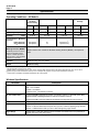
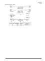
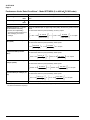
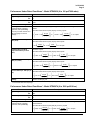
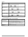
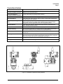
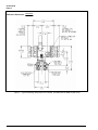
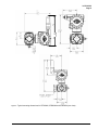
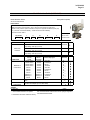
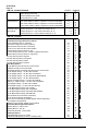
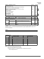
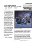
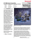
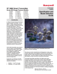
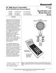
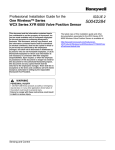
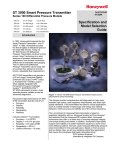
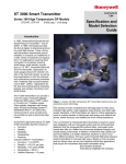
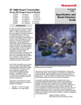
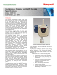
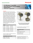
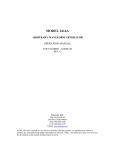
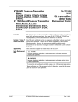
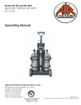
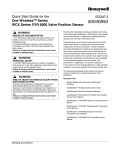
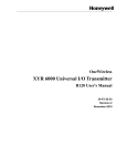
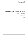
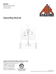
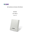
XYR 6000 Wireless Pressure Transmitter 34-XY-03-22 8/13/07 Differential Pressure Models STDW924 STDW930 STDW974 0 to 400 inH2O 0 to 100 psi 0 to 3000 psi Specification and Model Selection Guide 0 to 1,000 mbar 0 to 7,000 mbar 0 to 210,000 mbar a Introduction Building upon the tremendously successful ST 3000 series transmitter line; Honeywell brings simple, safe, and secure wireless technology to its measurement portfolio in the XYR 6000 Series Wireless Transmitters. The XYR 6000 series measurements are part of the WNSIA (Wireless Network for Secure Industrial Applications) compliant field devices. Measurement and information without wires! The XYR 6000 wireless transmitters series enable customers to obtain data and create information from remote and hazardous measurement locations without the need to run wires, where running wire is cost prohibitive and/or the measurement is in a hazardous location. Without wires, transmitters can be installed and operational in minutes, quickly providing information back to your system. XYR 6000 wireless transmitters send information to a multinode or series of multinodes creating a MESH infrastructure. Wireless System Gateways (WSG) provide the path to bring that information into Experion PKS or any other control system wirelessly via OPC client or Modbus-TCP. Each multinode accepts signals from up to 20 wireless transmitters reporting at 1 second, and up to 400 transmitters reporting at slower rates. Up to 20 multinodes can be implemented in the same infrastructure. WSG also provides Modbus-TCP data access to wireless data in addition to OPC. Transmitter power is supplied by two “D” size lithium batteries with an expected lifetime of up to ten years. Transmitter range with the integral antenna is 1000’ (305 m) under ideal conditions. Pressure transmitters continue to bring a proven technology to a wide spectrum of pressure measurement applications, from furnace combustion airflow rate to hydrostatic tank gauging. The STDW series Differential Pressure can be used with any primary flow element to provide proven, repeatable flow measurement. Figure 1 —XYR 6000 Differential Pressure Transmitters Implement the value of wireless technology today: • • • • • Measure remote access points simply, safe and securely Obtain and utilize previously inaccessible information due to high wiring cost or hazardous locations. Easily meet Regulatory Requirements Improve process efficiency Enhance Flexibility to monitor applications: - that have no access to power - that are remote or difficult to reach - that may require frequent reconfiguration - where manual readings have been required previously. 34-XY-03-22 Page 2 Specifications Operating Conditions – All Models Parameter Rated Condition Reference Condition (at zero static) Operative Limits Transportation and Storage °C °F °C °F °C °F Ambient Temperature 25 ±1 77 ±2 -40 to 85 -40 to 185 -40 to 85 -40 to 185 -40 to 85 -40 to 185 Meter Body Temperature 25 ±1 77 ±2 -40 to 110 -40 to 2301 -40 to 125 -40 to 257 -40 to 85 -40 to 185 Humidity %RH Vacuum Region - Minimum Pressure mmHg absolute inH2O absolute Maximum Allowable Working Pressure (MAWP) 4 (XYR6000 products are rated to Maximum Allowable Working Pressure. MAWP depends on Approval Agency and transmitter materials of construction.) 1 10 to 55 0 to 100 0 to 100 Atmospheric Atmospheric 25 13 2 (short term2) 1 (short term2) °C °F 0 to 100 STDW924,STDW930, STDW974 = 4500psi, 310 bar 3 Static Pressure Limit = Maximum Allowable Working Pressure (MAWP) = Overpressure Limit Vibration Maximum of 4g over 15 to 200Hz. Shock Maximum of 40g. 1 For CTFE fill fluid, the rating is –15 to 110°C (5 to 230°F) Short term equals 2 hours at 70°C (158°F) 3 MAWP applies for temperature range –40 to 125°C. However Static Pressure Limit is de-rated to 3000 psi from -26 to -40°C. Use of graphite o-rings de-rates transmitter to 3625 psi. Use of Adapter with graphite o-rings de-rates transmitter to 3000 psi. 4 Consult factory for MAWP of XYR6000 transmitters with CSA approval. 2 Wireless Specifications Parameter Wireless Communication Description 2,400 to 2,483.5 MHz (2.4 GHz) Frequency Hopping Spread Spectrum (FHSS) USA – FCC Certified Canada – IC Certified European Union – RTTE/ETSI Conformity RF Transmitter Power 125 mW (20.9 dBm) maximum per FCC/IC not including antenna, or 400 mW (26.0 dBm) maximum EIRP including antenna for USA and Canadian locations. 100 mW (20.0 dBm) maximum EIRP per RTTE/ETSI including antenna for EU locations. Data Rate: 250 Kbps Antennas Integral – 2 dBi omnidirectional monopole Remote – 8 dBi omnidirectional monopole with up to 20 m cable and lightning surge arrester. Remote – 14dBi Directional with up to 20 m cable and lightning surge arrester. Signal Range Nominal 305 m (1,000 feet) between Field Transmitter and Infrastructure Unit (multinode) or Gateway Unit with a clear line of sight.* *Actual range will vary depending on antennas, cables and site topography. 34-XY-03-22 Page 3 Remote antenna cables 34-XY-03-22 Page 4 Performance Under Rated Conditions* - Model STDW924 (0 to 400 inH2O/1000 mbar) Parameter Description Upper Range Limit inH2O mbar 400 (39.2°F/4°C is standard reference temperature for inH2O range.) 1000 Minimum Span inH2O mbar 10 25 Zero Elevation and Suppression –5 to +100% URL Accuracy (Reference – Includes combined effects of linearity, hysteresis, and repeatability) ±0.10% of calibrated span or upper range value (URV), whichever is greater, terminal based. • Accuracy includes residual error after averaging successive readings. For URV below reference point (25 inH2O), accuracy equals: ⎡ ⎛ 25 inH 2O ⎞⎤ ⎜ span inH O ⎟⎟⎥ ⎝ 2 ⎠⎦ ± ⎢0.125 + 0.05 ⎜ ⎣ Zero Temperature Effect per 28°C (50°F) ⎛ 125 mbar ⎞ ⎟ ⎝ span mbar ⎠ or ± 0.15⎜ in % of span For URV below reference point (50 inH2O), effect equals: ⎡ ⎢⎣ ⎛ 50 inH 2O ⎞⎤ ⎟ ⎝ span inH 2O ⎠⎥⎦ ⎡ ⎢⎣ or ± 0.075 + 0.15⎛ ⎜ 125 mbar ⎞⎤ ⎟ in % of span mbar ⎠⎥ ⎦ ⎝ span ±0.1625% of span. For URV below reference point (50 inH2O), effect equals: ⎡ ⎢⎣ ⎛ 50 inH 2O ⎞⎤ ⎟ ⎝ span inH 2O ⎠⎥⎦ ± 0.0125 + 0.15⎜ ⎡ ⎢⎣ or ± 0.0125 + 0.15⎛ ⎜ 125 mbar ⎞⎤ ⎟ in % of span mbar ⎠⎥ ⎦ ⎝ span ±0.30% of span. For URV below reference point (50 inH2O), effect equals: ⎡ ⎢⎣ ⎛ 50 inH 2O ⎞⎤ ⎟ ⎝ span inH 2O ⎠⎥⎦ ± 0.15 + 0.15⎜ Stability in % of span ±0.225% of span. ± 0.075 + 0.15⎜ Combined Zero and Span Static Pressure Effect per 1000 psi (70 bar) ⎣ For URV below reference point (50 inH2O), effect equals: ⎛ 50 inH 2O ⎞ ⎟ ⎝ span inH 2O ⎠ Zero Static Pressure Effect per 1000 psi (70 bar) ⎛ 62 mbar ⎞⎤ ⎟⎥ ⎝ span mbar ⎠⎦ ±0.15% of span. ± 0.15⎜ Combined Zero and Span Temperature Effect per 28°C (50°F) ⎡ or ± ⎢0.125 + 0.05⎜ ⎡ ⎢⎣ 125 mbar ⎞⎤ ⎟ in % of span span mbar ⎠⎥ ⎝ ⎦ or ± 0.15 + 0.15⎛ ⎜ ±0.015% of URL per year * Performance specifications are based on reference conditions of 25°C (77°F), zero (0) static pressure, 10 to 55% RH, and 316L Stainless Steel barrier diaphragm. 34-XY-03-22 Page 5 Performance Under Rated Conditions* - Model STDW930 (0 to 100 psi/7000 mbar) Parameter Description Upper Range Limit psi bar 100 7 Minimum Span psi bar 5 0.35 Zero Elevation and Suppression –5 to +100% URL. Accuracy (Reference – Includes combined effects of linearity, hysteresis, and repeatability) ±0.10% of calibrated span or upper range value (URV), whichever is greater, terminal based. •Accuracy includes residual error after averaging successive readings. Zero Temperature Effect per 28°C (50°F) For URV below reference point (20 psi), accuracy equals: ⎡ ⎞⎤ ⎟⎟⎥ ⎝ span psi ⎠⎦ ⎛ ± ⎢0.125 + 0.05⎜ ⎜ ⎣ ⎛ 2 bar ⎞ ⎟ ⎝ span bar ⎠ or ± 0.15⎜ in % of span in % of span ±0.225% of span. For URV below reference point (30 psi), effect equals: ⎡ ⎢⎣ ⎛ 30 psi ⎞⎤ ⎟ ⎝ span psi ⎠⎥⎦ ± 0.075 + 0.15⎜ ⎡ ⎢⎣ or ± 0.075 + 0.15⎛ ⎜ 2 bar ⎞⎤ ⎟ in % of span bar ⎠⎥ ⎦ ⎝ span ±0.1625% of span. For URV below reference point (30 psi), effect equals: ⎡ ⎢⎣ ⎛ 30 psi ⎞⎤ ⎟ ⎝ span psi ⎠⎥⎦ ± 0.0125 + 0.15⎜ Combined Zero and Span Static Pressure Effect per 1000 psi (70 bar) ⎣ For URV below reference point (30 psi), effect equals: ⎛ 30 psi ⎞ ⎟ ⎝ span psi ⎠ Zero Static Pressure Effect per 1000 psi (70 bar) ⎛ 1.4 bar ⎞⎤ ⎟⎥ ⎝ span bar ⎠⎦ ⎡ or ± ⎢0.0125 + 0.05⎜ ±0.15% of span. ± 0.15⎜ Combined Zero and Span Temperature Effect per 28°C (50°F) 20 psi ⎡ ⎢⎣ or ± 0.0125 + 0.15⎛ ⎜ 2 bar ⎞⎤ ⎟ in % of span bar ⎠⎥ ⎦ ⎝ span ±0.30% of span. For URV below reference point (30 psi), effect equals: ⎡ ⎢⎣ ⎛ 30 psi ⎞⎤ ⎟ ⎝ span psi ⎠⎥⎦ ± 0.15 + 0.15⎜ ⎡ ⎢⎣ or ± 0.15 + 0.15⎛ ⎜ 2 bar ⎞⎤ ⎟ in % of span bar ⎠⎥ ⎦ ⎝ span ±0.04% of URL per year Stability * Performance specifications are based on reference conditions of 25°C (77°F), zero (0) static pressure, 10 to 55% RH, and 316L Stainless Steel barrier diaphragm. Performance Under Rated Conditions* - Model STDW974 (0 to 3000 psi/210 bar) Parameter Description Upper Range Limit psi bar 3000 210 Minimum Span psi bar 100 7 Zero Elevation and Suppression –0.6 and +100% URL. Accuracy (Reference – Includes combined effects of linearity, hysteresis, and repeatability) ±0.175% of calibrated span or upper range value (URV), whichever is greater, terminal based. For URV below reference point (300 psi), accuracy equals: ⎡ ⎢⎣ ⎛ 300 psi ⎞⎤ ⎟ ⎝ span psi ⎠⎥⎦ ± 0.025 + 0.15⎜ ⎡ ⎢⎣ or ± 0.025 + 0.15⎛ ⎜ 21 bar ⎞⎤ ⎟ in % of span bar ⎠⎥ ⎦ ⎝ span 34-XY-03-22 Page 6 Parameter Zero Temperature Effect per 28°C (50°F) Description ±0.20% of span. For URV below reference point (500 psi), effect equals: ⎛ 500 psi ⎞ ⎟ ⎝ span psi ⎠ ± 0.20⎜ Combined Zero and Span Temperature Effect per 28°C (50°F) For URV below reference point (500 psi), effect equals: ⎡ ⎢⎣ ⎛ 500 psi ⎞⎤ ⎟ ⎝ span psi ⎠⎥⎦ ⎛ 35 bar ⎞⎤ ⎟ ⎝ span bar ⎠⎥⎦ in % of span For URV below reference point (500 psi), effect equals: ⎡ ⎢⎣ ⎛ 500 psi ⎞⎤ ⎟ ⎝ span psi ⎠⎥⎦ 35 bar ⎞⎤ ⎟ in % of span span bar ⎠⎥ ⎝ ⎦ ⎡ ⎢⎣ or ± 0.0125 + 0.15⎛ ⎜ ±0.30% of span. For URV below reference point (500 psi), effect equals: ⎡ ⎢⎣ ⎛ 500 psi ⎞⎤ ⎟ ⎝ span psi ⎠⎥⎦ ± 0.15 + 0.15⎜ 35 bar ⎞⎤ ⎟ in % of span span bar ⎠⎥ ⎝ ⎦ ⎡ ⎢⎣ or ± 0.15 + 0.15⎛ ⎜ ±0.03% of URL per year Stability • ⎡ ⎢⎣ or ± 0.10 + 0.20⎜ ±0.1625% of span. ± 0.0125 + 0.15⎜ Combined Zero and Span Static Pressure Effect per 1000 psi (70 bar) in % of span ±0.30% of span. ± 0.10 + 0.20⎜ Zero Static Pressure Effect per 1000 psi (70 bar) ⎛ 35 bar ⎞ ⎟ ⎝ span bar ⎠ or ± 0.20⎜ Performance specifications are based on reference conditions of 25°C (77°F), zero (0) static pressure, 10 to 55% RH, and 316L Stainless Steel barrier diaphragm. Performance under Rated Conditions – General for all Models Parameter Description Lightning Surge Arrester (Remote antenna only) Frequency range: 0 – 3 GHz, 50 Ohms, VSWR = 1:1.3 Max, Insertion Loss = 0.4 dB Connectors Type N Female, Max, Gas Tube Element: 90 V ± 20%, Impulse Breakdown Voltage = 1,000 V ± 20%, Maximum Withstand Current = 5 KA. CE Conformity These transmitters are in conformity with the protection requirements of European Council Directives: 89/336/EEC, the EMC Directive and 1999/5/EC, the Telecommunications Directive per EN 300 328 V1.7.1, EN301 893 V1.3.1, EN301 489-17 V1.2.1, EN301 489-1 V1.6.1 and EN61326-1 (1st Edition, 2002-02, Industrial Locations). Electrical Equipment for Measurement, Control and Laboratory Use – EMC Requirements. Hazardous Location Certifications See the Model Selection Guide on page 11. 34-XY-03-22 Page 7 Physical Specifications Parameter Description Barrier Diaphragms Material STDW924, STDW930, STDW974 316L SS, Hastelloy C-276, Monel, Tantalum, Gold plated 316LSS, Gold plated Hastelloy C-276, Gold plated Monel Process Head Material STDW924, STDW930, STDW974 316 SS, Carbon Steel (zinc-plated), Monel, Hastelloy Head Gaskets Glass filled PTFE standard. Viton and graphite optional. Meter Body Bolting Carbon Steel (Zinc plated) standard. Options include 316 SS, NACE A286 SS bolts with NACE 304 SS nuts, and B7M. Optional Adapter Flange and Bolts Adapter Flange materials include 316 SS, Hastelloy C-276 and Monel. Options for bolting include carbon steel, 316SS, NACE A286SS and B7M. Standard adapter flange gasket material is glass filled PTFE. Viton and graphite optional. Mounting Bracket Carbon Steel (Zinc-plated) or Stainless Steel angle bracket or Carbon Steel flat bracket available (standard options). Fill Fluid Silicone DC 200 oil or CTFE (Chlorotrifluoroethylene) Electronic Housing Epoxy-Polyester hybrid paint. Low Copper-Aluminum. Meets NEMA 4X (hosedown and corrosion resistant), IP 66/67 (hosedown and submersible to 1m). Process Connections 1/4-inch NPT; 1/2-inch NPT with adapter. Process heads meet DIN 19213 requirements. Mounting Can be mounted in virtually any position using the standard mounting bracket. Mounting should result in the antenna being vertically oriented. Bracket is designed to mount on 2-inch (50 mm) vertical or horizontal pipe. See Figure 2 . Dimensions See Figure 3 and Figure 4. Net Weight Approximately 11 pounds (5 Kg) Figure 2 —Examples of typical mounting positions 34-XY-03-22 Page 8 Reference Dimensions: millimeters inches Figure 3 —Typical mounting dimensions for STDW924, STDW930 and STDW974 (side view) 34-XY-03-22 Page 9 240,80 9.48 Figure 4 Typical mounting dimensions for STDW924, STDW930 and STDW974 (rear view) 34-XY-03-22 Page 10 Options Mounting Bracket The angle mounting bracket is available in either zinc-plated carbon steel or stainless steel and is suitable for horizontal or vertical mounting on a two inch (50 millimeter) pipe, as well as wall mounting. An optional flat mounting bracket is also available in carbon steel for two inch (50 millimeter) pipe mounting. Ordering Information Tagging (Option TG) Up to 30 characters can be added on the stainless steel nameplate mounted on the transmitter’s electronics housing at no extra cost. Note that a separate nameplate on the meter body contains the serial number and body-related data. A stainless steel wired on tag with additional data of up to 4 lines of 28 characters is also available. The number of characters for tagging includes spaces. Contact your nearest Honeywell sales office, or Transmitter Configuration All configurable parameters are accessible via the WNSIA network via READ/WRITE transactions. In Latin America: Honeywell Inc. 480 Sawgrass Corporate Parkway, Suite 200 Sunrise, FL 33325 (954) 845-2600 In the U.S.: Honeywell Industrial Automation & Control 16404 North Black Canyon Hwy. Phoenix, AZ 85053 1-800-288-7491 In Canada: The Honeywell Centre 155 Gordon Baker Rd. North York, Ontario M2H 3N7 1-800-461-0013 In Europe and Africa: Honeywell S. A. Avenue du Bourget 1 1140 Brussels, Belgium In Eastern Europe: Honeywell Praha, s.r.o. Budejovicka 1 140 21 Prague 4, Czech Republic In the Middle East: Honeywell Middle East Ltd. Khalifa Street, Sheikh Faisal Building Abu Dhabi, U. A. E. In Asia: Honeywell Asia Pacific Inc. Honeywell Building, 17 Changi Business Park Central 1 Singapore 486073 Republic of Singapore In the Pacific: Honeywell Pty Ltd. 5 Thomas Holt Drive North Ryde NSW Australia 2113 (61 2) 9353 7000 In Japan: Honeywell K.K. 14-6 Shibaura 1-chrome Minato-ku, Tokyo, Japan 105-0023 Specifications are subject to change without notice. Or, visit Honeywell on the World Wide Web at: http://www.honeywell.com 34-XY-03-22 Page 11 Model Selection Guide (34-XY-16-38) Model Selection Guide 34-XY-16-38 Issue 2 Honeywell Proprietary Instructions Select the desired Key Number. The arrow to the right marks the selection available. Make one selection from each table, I and II, using the column below the proper arrow. Select as many Table III options as desired (if no options or approvals are desired, specify 9X). A () denotes unrestricted availability. A letter denotes restricted availability. Restrictions follow Table V. List Price equals Key Number STDW_ _ _ I - ___ II - 00000 IV III - _____ - _ _, _ _, _ _ - V XXXX the sum of all selections made. Selection Availability KEY NUMBER Differential Pressure TABLE I METER BODY Materials of Construction Fill Fluid Process Head Configuration Span 0-10" to 0-400" H2O/0-25 to 0-1000 mbar Body Rating: 4500 psi (310 bar) 0-5 to 0-100 psi/0-0.34 to 0-7 bar Body Rating: 4500 psi (310 bar) 0-100 to 0-3000 psi/0-7 to 0-210 bar Body Rating: 4500 psi (310 bar) Wetted Process Heads Vent/Drain Valves ** and Plugs Barrier Diaphragms 316 SS Carbon Steel * 316L SS 316 SS Carbon Steel * Hastelloy C 316 SS Carbon Steel * Monel 316 SS Carbon Steel * Tantalum 316 SS 316 SS 316L SS 316 SS 316 SS Hastelloy C 316 SS 316 SS Monel 316 SS Tantalum 316 SS Hastelloy C Hastelloy C Hastelloy C Hastelloy C Hastelloy C Tantalum Monel Monel Monel Silicone CTFE 1/4" NPT 1/2" NPT with Adapter (on 1/4" NPT Head) TABLE II No Selection * Carbon Steel heads are zinc-plated. ** Vent/Drains are Teflon coated for lubricity. STDW924 STDW930 STDW974 Selection A__ B__ C__ D__ E__ F__ G__ H__ J__ K__ L__ _1_ _2_ __A __H y y y y y y y y y y y y y y 00000 y k Not recommended for water service due to hydrogen migration. Use Stainless Steel heads. 34-XY-03-22 Page 12 TABLE III - ANTENNA OPTIONS Antenna's Integral Right-angle, vertical (Standard) Integral Straight, horizontal Remote Omnidirectional, 8 dBi Remote Directional, 14 dBi Cable A for None Remote Antenna 1.0m remote Cable A, TNC-R - N (Req'd to connect to XYR 6000) 3.0m remote Cable A, TNC-R - N (Req'd to connect to XYR 6000) 10.0m remote Cable A, TNC-R - N (Req'd to connect to XYR 6000) Lightning Protection None for remote Antenna Lightning Protection + 1.0m Cable B to Antenna, N - N With Cable B Lightning Protection + 3.0m Cable B to Antenna, N - N Lightning Protection + 10.0m Cable B to Antenna, N - N TABLE IV - OPTIONS None Transmitter Housing & Electronics Options Custom Calibration and I.D. in Memory Transmitter Configuration and ID in Memory M20 Conduit Thread (1/2" NPT is standard) 1/2" NPT to 3/4" NPT 316 SS Conduit Adapter Stainless Steel Customer Wired-On Tag (4 lines, 28 characters per line, customer supplied information) Stainless Steel Customer Wired-On Tag (blank) End Cap Warning Label in Spanish End Cap Warning Label in Portuguese End Cap Warning Label in Italian End Cap Warning Label in German Meter Body Options 316 SS Bolts and 316 SS Nuts for Process Heads B7M Bolts and Nuts for Process Heads NACE A286 SS Bolts and NACE 304 SS Nuts for Process Heads 316 SS Adapter Flange - 1/2" NPT with CS Bolts 316 SS Adapter Flange - 1/2" NPT with 316 SS Bolts 316 SS Adapter Flange - 1/2" NPT with NACE A286 SS Bolts 316 SS Adapter Flange - 1/2" NPT with B7M Bolts Hastelloy C Adapter Flange - 1/2" NPT with CS Bolts Hastelloy C Adapter Flange - 1/2" NPT with 316 SS Bolts Monel Adapter Flange - 1/2" NPT with CS Bolts Monel Adapter Flange - 1/2" NPT with 316 SS Bolts 316 SS Blind Adapter Flange with CS Bolts 316 SS Blind Adapter Flange with 316 SS Bolts 316 SS Blind Adapter Flange with NACE A286 SS Bolts 316 SS Blind Adapter Flange with B7M Bolts Side Vent/Drain (End Vent Drain is standard) 316 SS Center Vent Drain and Bushing Viton Process Head Gaskets (adapter gaskets ordered separately) Viton Adapter Flange Gaskets Graphite Process Head & Adapter Flange Gaskets Transmitter Mounting Brackets Options Mounting Bracket - Carbon Steel Mounting Bracket - 304 SS Flat Mounting Bracket - Carbon Steel Diaphragm Options Gold plated diaphragm(s) on 316 SS Gold plated diaphragm(s) on Monel or Hastelloy ONLY Selection V____ S____ M____ D____ _00_ _ _01__ _03__ _10__ ___00 ___01 ___03 ___10 Availability d d e e y y y y y y y y 00 y CC TC A1 A2 TG y y y y y TB SP PG TL GE y y y y y b SS B7 CR S2 S3 S4 S5 T2 T3 V2 V3 B3 B4 B5 B6 SV CV VT VF GF y y y b y y y y y y y y y MB SB FB y y y b b c c c c c c c c b b b y G1 b y G2 Table IV continued on next page 34-XY-03-22 Page 13 TABLE IV - OPTIONS (continued) Services/Calibration/Conformance Options User's Manual Paper Copy Clean Transmitter for Oxygen or Chlorine Service with Certificate Over-Pressure Leak Test with F3392 Certificate Calibration Test Report and Certificate of Conformance (F3399) Certificate of Conformance (F3391) Certificate Options Certificate of Origin (F0195) NACE Certificate (F0198) Warranty Options Additional Warranty - 1 year Additional Warranty - 2 years Approval Body Approval Type No hazardous location approvals Nonincendive CSA cus Non-Sparking ATEX Non-Sparking Selection Availability UM 0X TP F1 F3 y h y y y F5 F7 y i W1 W2 y y 9X y 2N y 3N y Nonincendive, CL I, Div 2, Groups A,B,C & D, CL II & III, Div 2, Groups F & G, T4 Ta = 85°C Class I, Ex/AEx nC IIC; T4, Ta ≤ 85°C, Zone 2; IP 66 Ex II 3 GD; Ex nL IIC; T4, Ta ≤ 85°C, Zone 2; IP 66/67 TABLE V Factory Identification XXXX RESTRICTIONS Available Only With Restriction Letter Table Selection b Select only one option from this group __H c I _ 00 _ _ , _ _ _ 00 III d e Table Not Available With Selection III I IV IV b Location or Classification WARNING – Division 2 / Zone 2 apparatus may only be connected to processes classified as non-hazardous or Division 2 / Zone 2. Connection to hazardous (flammable or ignition capable) Division 1 / Zone 0, or 1 process is not permitted. h i k b _2_ CR, S4, B5 Select from Table IV S2, S3, S4, S5, T2, T3, V2, V3 Notes: See ST-89 for Published Specials with pricing. See ST-95 and User's Manual for part numbers. To request a quotation for a non-published "special", fax RFQ to 602-313-6155 or email to [email protected] _ 00 _ _ y b 34-XY-03-22 Page 14 OneWireless and XYR are trademarks and Experion is a registered trademark of Honeywell International Inc. Honeywell Field Solutions Honeywell International Inc. 2500 W. Union Hill Drive Phoenix, Arizona 85027 ©Honeywell International Inc.