1
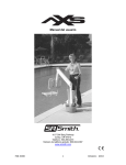
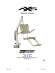
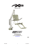
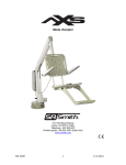
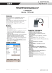
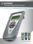
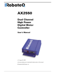
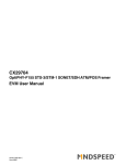
OWNERS MANUAL
VOL1 - ISSUE1
A division of
RehaMed International, LLC.
522 W. Mowry Drive • Homestead, FL 33030
Tel: 305-247-8300
Toll Free: 800-577-4424
http://www.grouprmt.com
1
TABLE OF CONTENTS
aXs Aquatic Lift System
Introduction . . . . . . . . . . . . . . . . . . . . . . . . . . . . . . . . . . . . . . . . . .
3
Product Overview . . . . . . . . . . . . . . . . . . . . . . . . . . . . . . . . . . . . .
5
Component Description . . . . . . . . . . . . . . . . . . . . . . . . . . . . . . . . .
6
Unpacking & Assembly Instructions . . . . . . . . . . . . . . . . . . . . . . .
9
Operating the aXs . . . . . . . . . . . . . . . . . . . . . . . . . . . . . . . . . . . . .
10
Emergency Operations . . . . . . . . . . . . . . . . . . . . . . . . . . . . . . . . . .
10
Deck Anchor Installation . . . . . . . . . . . . . . . . . . . . . . . . . . . . . . . .
11
Battery Charging . . . . . . . . . . . . . . . . . . . . . . . . . . . . . . . . . . . . . .
12
Accessories . . . . . . . . . . . . . . . . . . . . . . . . . . . . . . . . . . . . . . . . . .
13
Maintenance . . . . . . . . . . . . . . . . . . . . . . . . . . . . . . . . . . . . . . . . . .
14
Long Term Storage . . . . . . . . . . . . . . . . . . . . . . . . . . . . . . . . . . . .
14
Trouble Shooting . . . . . . . . . . . . . . . . . . . . . . . . . . . . . . . . . . . . . .
15
Warranty . . . . . . . . . . . . . . . . . . . . . . . . . . . . . . . . . . . . . . . . . . . . . 16-17
Product Specifications
– Dimensions/Capacity . . . . . . . . . . . . . . . . . . . . . . . . . . . . . . .
18
– Actuator . . . . . . . . . . . . . . . . . . . . . . . . . . . . . . . . . . . . . . . . . .
18
– Battery Information . . . . . . . . . . . . . . . . . . . . . . . . . . . . . . . . .
18
– Range of Motion . . . . . . . . . . . . . . . . . . . . . . . . . . . . . . . . . . .
18
– Materials and Finish . . . . . . . . . . . . . . . . . . . . . . . . . . . . . . . .
19
Parts List . . . . . . . . . . . . . . . . . . . . . . . . . . . . . . . . . . . . . . . . . . . .
20
2
INTRODUCTION
The purpose of this document is to provide information relating to the operation,
care and maintenance of the aXs Aquatic Lift System.
Our goal is to provide our customers with the most advanced and innovative
designs that offer exceptional quality at affordable prices. We design and
manufacture our products so that all individuals with disabilities and mobility
impairments can have access and enjoy the recreational activity of their choice.
We offer lifts for virtually any type of aquatic environment, including those
under the mandates of ADAAG 2004.
Please feel free to contact us if you have any questions about our current product
line or if there is anything we can do to help meet your accessibility needs.
aXs and aXs logo are registered trademarks
of RehaMed International, LLC.
3
STANDARD aXs
4
THE aXs –
SEMI-PORTABLE AQUATIC LIFT SYSTEMS
PRODUCT OVERVIEW
The aXs is specifically designed for both residential applications as well as
hospitality and multi-unit facilities who are seeking a sensible solution for
providing access to their swimming pools for users with disabilities.
The aXs is easy to operate and maintain, is transportable, is reliable, and is
priced to fit into any budget. In addition, the aXs features an attractive design
which blends into any pool environment without projecting an institutional
appearance.
Standing a mere 32 inches above the deck, the aXs provides 360º rotation to
insure sufficient clear deck space for safe transfers on and off the lift. The aXs
is intended to be used with simple pool gutter configurations having a deck to
water distance of no more than six inches.
The aXs is fabricated using both aluminum extrusions and stainless steel. All
surfaces are treated with a tough and attractive powder coated finish to protect
against prolonged exposure to the elements. Custom colors are available. The
housing is formed from ABS plastic with an acrylic cap to minimize
discoloration due to exposure to the sun.
With a lifting capacity of 300 pounds, the Basic versions of the aXs meets all
Americans with Disabilities Act Accessibility Guidelines (ADAAG), and
features our exclusive seating system. This system, designed by people with
disabilities for people with disabilities, is wider and deeper than most
conventional seats, and has no edges to restrict transfers.
5
PRODUCT COMPONENTS
STANDARD aXs
Component Description
The following are the key components used in the aXs:
Base Assembly: The base assembly (not shown) connects the aXs to the pool
deck and includes the turning elements of the lift. The insert portion of the base
assembly is inserted into the deck anchor. The mast is attached to the base
assembly using two nylon locking nuts.
Mast: The main vertical component of the lift, the mast is fabricated in stainless
steel and treated with a durable powder coated finish.
Actuator Arm: Primary lifting arm of the lift. Fabricated from an aluminum
extrusion, the actuator arm connects the mast to the seat arm and is raised by the
attached actuator. The actuator arm is treated with a durable powder coated
finish.
6
Component Description- continued
Support Arm: Provides stability for the seat arm. Fabricated from an aluminum
extrusion, the seat arm nests inside the actuator arm to provide a unified look and
avoid pinch points. The support arm is treated with a durable powder coated finish
Seat Arm: Provides an attachment point for the seat assembly. Fabricated from an
aluminum extrusion and treated with a durable powder coated finish.
Housing: Two piece housing covers the turning components and gears. Fabricated
from ABS plastic with an acrylic cap to minimize discoloration due to extended
exposure to the sun and pool chemicals. The attractive finish of the housing is
suceptible to scratching. When cleaning the housing, be sure to use a clean, soft,
non-abrasive material.
Actuator: Provides the up and down lifting action.
Turning Motor: This 24v gear motor provides the turning action on Basic models.
Control Box: Forms the bottom of the control console; this unit controls the
mechanical operations of the lift. Three cables connect to the bottom of the
Control Box. The largest receptacle is the connection for the hand control. The
receptacle next to the hand control connector is marked number 1 and is used to
connect the Actuator cable. The next receptacle is marked number 2 and is used
to connect the cable for the Turning Motor.
Battery: The removable Battery is located on top of the Control Box. Please
carefully read the information on Battery charging and the warranty information
relating to the Battery.
Battery Charger: The Charger connects to the charging slot
on the bottom of the Battery where it connects to the Control
Box. Please carefully read the information on Battery charging
and the warranty information relating to the Battery.
7
Hand Control: The four button unit controls all lift
movements for the Basic Model. The two button unit
controls the up and down movements of the aXs MT
(manual turning version). The arrows indicate the direction
of movement. All Hand Controls are fully waterproof and
meet IP67 standards.
Seating System: The seating system used with all RMT aquatic lifts is the
product of years of feedback from our customers and information gathered from
focus groups comprised of users of our lifts. Unlike many lift seats that are
standard “lifeguard type” plastic shells, this is the first such system that is
specifically designed for disabled swimmers.
The seat itself is both deeper and higher to provide both a more stable platform
for sitting, as well as being able to accommodate swimmers with reduced trunk
stability. The seat has been flattened considerably to eliminate any ridge that
would hamper transferring. The sections of the seat have attachment points for
the standard seat belt assembly as well as our optional Stability Vest. The molded
plastic footrest is removable and will float upward to prevent damage if the chair
is lowered too low impacting the deck.
The optional arm rests are robust and can be used for support when transferring
on and off the seat. They can be flipped up and out of the way during a transfer.
8
UNPACKING & ASSEMBLY INSTRUCTIONS
REFER TO THE DIAGRAM (page 5) FOR PARTS IDENTIFICATION.
READ THESE INSTRUCTIONS IN THEIR ENTIRETY BEFORE
BEGINNING INSTALLATION
Prior to opening the shipping pallet, carefully inspect the external condition
of the shipping materials for any visible damage. It is important that any
damage be noted on the Bill of Lading prior to signing for the delivery.
Contact either RehaMed or your dealer immediately to notify us of any
damage or missing parts.
The deck anchor should be installed following the installation instructions.
The aXs is shipped on a covered pallet. The lift is shipped almost totally assembled,
so no tools are required for installation and set up. If possible, position the container
as close to the deck anchor as possible to facilitate the process.
Follow these steps to unpack and set up the aXs:
1.
2.
3.
4.
5.
6.
7.
Carefully remove the plastic covering from the pallet.
Carefully remove any wood bracing from the pallet.
Remove the lift from the pallet and place into the deck anchor.
Locate the accessory box and install the battery and hand control.
Rotate the lift so that the seat arm is positioned over the pool deck.
Attach the seat to the seat arm. Attach the foot rest to the seat.
The lift is now ready for use.
9
OPERATING THE aXs
Follow these steps to operate the aXs:
•
•
•
•
•
•
•
•
•
•
Rotate the seat to either side of the lift that is the most comfortable position
for transfer. The lift rotates 360º, so position the lift well over the pool deck
away from the edge of the pool.
Adjust the height of the chair for a comfortable transfer.
Transfer onto the seat and fasten the seat belt.
Raise the seat so there is ample legroom for travel.
Rotate the lift over the water and lower the seat into the water. The hand
control is waterproof, so keep it attached to the seat while swimming.
Enjoy your swim.
Following your swim, move back onto the seat and fasten the seat belt.
Raise the lift out of the water and rotate the seat over the pool deck.
Adjust the height of the chair for a comfortable transfer.
Transfer off the lift.
EMERGENCY OPERATIONS
Although the electronic system used on the aXs is the same technology used on
thousands of lifting products throughout the world, there is always the unlikely
event that the product will not operate properly when needed. To anticipate any
mechanical failure, the following safeguards are engineered into the aXs:
Lifting failure: In the event of a lifting failure, there is an emergency capacitor
built into the control box to provide enough power to lift the seat out of the water.
Use a blunt object, like the cap of a ball point pen, to press the appropriate up or
down emergency button located above the LCD Display on the control box.
Turning failure: If the lift will not turn electronically, you can remove the
housing and pull out the spring pin located next to the turning motor. This will
disengage the gears and allow the lift to be turned manually.
Please call RMT Aquatics at 800-577-4424
if you have any problems or questions with assembly.
10
DECK ANCHOR INSTALLATION
The optimal mounting distance for the deck anchor is between 12 and 18 inches
from the edge of the pool. The aXs is designed to be used with simple pool edge
designs without protruding gutters. Please call RehaMed International with any
questions concerning deck anchor placement or if the aXs will work in your
installation.
Concrete Pool Decks
The deck anchor should be totally encapsulated in
concrete. Make sure that there are no air pockets or
empty space around the anchor.
Follow these suggestions to make sure your anchor
is installed properly:
• Determine the proper location to install the
Deck Anchor
anchor.
• Use a core drill to drill a hole, between 5 and 6 inches in diameter, into the
concrete deck. Be sure the hole is at least 7 inches deep. This will likely be
deeper than the deck is thick, but the depth is important to insure that the
anchor is completely encapsulated in cement.
• Clean all debris from the hole.
• Place the anchor into the hole. Be sure that the anchor is plumb and the
top of the anchor is flush with the surface of the deck.
• Fill the cavity with anchoring cement. Be careful to keep the cement out of
the sleeve.
• Allow the cement to cure according to the manufacturer’s instructions.
Wooden Decks
The aXs can also be used with a wooden pool deck, however this type of installation
will require a special anchor. Since this anchor will need to be fabricated to match
the design of the deck, the design and installation will likely be different for each
deck.
Please contact RehaMed International and we can work with you to gather the
necessary information for fabricating this custom anchor.
11
BATTERY CHARGING
The rechargeable battery should be connected to
the charger when the lift is not in use. A fully
charged battery will last approximately 30 lifting
cycles, depending on the weight of the user. The
battery has no memory, so it is not necessary to
discharge the battery prior to charging. In fact,
allowing the battery to fully discharge could cause
damage and shorten the life of the battery.
The battery is fully charged when shipped, but should be checked by looking at
the LCD display on the control box prior to use.
Please call RMT Aquatics at 800-577-4424
if you have any problems or questions with assembly.
12
ACCESSORIES
The following accessories are included with each aXs lift:
• Seat Belt Assembly
• Console Cover
• Foot Rest
The following optional accessories may be purchased for use with your aXs lift:
• Arm Rest Kit: Powder coated, stainless steel arm rests provide security and a
stable surface for transferring.
• Total Cover: Made of weather resistant polyester
• Stability Vest: Five point restraint for individuals who need a higher degree
of stability.
• Seat Pad: Waterproof seat pad designed to enhance
comfort and minimize potential skin damage that could
occur during transfer.
• Caddie for aXs: Highly recommended for all aXs models.
Designed to lift unit out from anchor socket and roll to
storage or other location if desired.
13
Caddie
MAINTENANCE
Minimal maintenance will prolong the life of your aXs lift.
All electronic components should be kept clean and dry. The control box and battery should be protected from exposure to water. A waterproof console cover is provided with each aXs to cover these components and protect them from sudden rain
showers or dousing with pool water. If the lift is used outdoors, a full cover is
available and should be used.
The following table details suggested maintenance guidelines:
Maintenance Performed
Daily
Rinse seat with fresh water and dry entire lift
Charge the Battery
Wipe control box and battery connection with
a clean dry rag
Examine lift for any damage
Test for normal operation
Weekly
Monthly
!
!
!
!
!
Spray gear assembly with corrosion inhibitor
Clean all connections with Scotch-Brite pad
Clean all metallic surfaces with cleaner wax
to maintain the finish of the lift
Make sure all connections are secure
!
!
!
!
Clean housing with soapy water and a soft
clean cloth. Do not use any kind of solvent on
the housing.
LONG-TERM STORAGE
The following steps should be taken to prepare the aXs for long term storage:
•
•
•
•
Rinse seat with fresh water and dry entire lift
Spray gear assembly with corrosion inhibitor
Keep battery connected to charger in a dry area
Cover unit and store in a dry location
14
TROUBLE SHOOTING
Be sure the battery is fully charged before troubleshooting.
Unit does not rotate
Does unit raise or lower?
Yes.
1. Check connection to Control Box. Be sure plug is pushed in all the way.
2. Check hand control connection to Control Unit for damaged pins.
3. Check connections on terminal block located on frame for loose wires.
4. Check connection cable for damage.
5. Reverse the motor cables as follows: Locate the area on the control box
where the cables are attached. Remove the actuator cable from
receptacle #1 and replace it with the 24v motor cable from receptacle
#2. Activate the up and down buttons on the hand control. If the unit
rotates, the problem is likely the hand control. If the unit does not rotate,
the problem is likely the 24v motor.
No.
1. Check battery charge level.
2. Check battery connection.
3. Use another fully charged battery. If unit continues to not function,
replace the control unit.
Unit does not Raise or Lower
Does unit rotate?
Yes.
1. Check connection to Control Box. Be sure plug is pushed in all the way.
2. Check hand control connection to Control Unit for damaged pins.
3. Check connection cable for damage.
4. Locate Emergency Buttons on top of Control Unit. Activate these
buttons using a ball point pen. If unit operates properly, the problem is
likely the hand control. If unit does not operate properly, the problem is
likely the actuator.
No.
1. Check battery charge level.
2. Check battery connection.
3. Use another fully charged battery. If unit continues to not function,
replace the control unit.
If these steps have not corrected your problem, call us at 800-577-4424.
15
WARRANTY INFORMATION
All RMT Aquatic Lifting Systems have a Lifetime Warranty on the frame,
excluding the powder coated paint finish, which may become scratched with
normal use. All electronic and motor components, with the exception of batteries,
have a full two-year warranty. Within the warranty period, we will repair or replace
any part found to be defective upon our examination, but will not pay shipping
costs or other expenses. To obtain warranty service, call or write to us at the
address provided. This warranty is an exclusive remedy and we are not responsible
for any consequential or incidental damages or injury to person or property. This
warranty shall not apply to any product which has been subject to misuse,
negligence, or accident, or has been damaged in shipment, or misapplied, or which
have been modified or repaired by an unauthorized person. This warranty only
applies to products owned by persons purchasing directly from the manufacturer
or from our approved dealers or distributors.
Warranty Procedures
To initiate a warranty claim, contact our customer service department. Once the nature
of the problem has been determined the following procedure will be followed:
Within the first 90 days following delivery of the Product
1. A Return Goods Authorization (RMA) will be issued for the return of
the defective component. This RGA number should be clearly displayed on
the outside of the package containing the returned part.
2. RMT will pay all freight charges for any component that fails within the first 90
days.
3. The defective component will be inspected by our technical staff to determine
if the product can be repaired. If the component cannot be repaired it will be
replaced with a new component.
After 90 days
1. A Return Goods Authorization (RMA) will be issued for the return of
the defective component. This RGA number should be clearly displayed on
the outside of the package containing the returned part.
2. The customer is responsible for all freight costs after 90 days.
3. The defective component will be inspected by our technical staff to determine
if the product can be repaired. If the component cannot be repaired it will be
replaced with a remanufactured component.
16
Batteries
Batteries have a normal lifespan of between 2-3 years, depending on their use
and care. Batteries should be left on the charger when not in use and should
never allowed to fully discharge. Allowing the battery to fully discharge can
damage the battery.
The battery has contacts located on the bottom of the battery housing. The battery
should never be placed on a conductive surface that would cause a short. If this
occurs, it is likely that the fuse located inside the housing would break. This fuse
can be replaced and should be changed prior to submitting a warranty claim.
All batteries are inspected prior to shipment, and, as such, should be free from
any manufacturing defect. That being said, the following is the warranty policy
for batteries:
1. If the battery fails during the first 90 days following purchase, it will be
replaced using the same guidelines for any warranty part.
2. If the battery fails during the first year following purchase, a new battery
will be provided at a charge of 50% of the prevailing cost of a new battery.
3. The warranty policy on batteries expires after one year following purchase.
What if I can’t wait for the defective component to be inspected?
If the customer desires that a replacement component be sent out immediately,
the following procedures will be followed:
1. Once the problem component has been identified, a remanufactured
component will be sent to the customer immediately.
2. The customer will be invoiced for the cost of a remanufactured componen
generally 75% of the full price.
3. A Return Goods Authorization (RGA) will be issued for the return of the
defective component. This RGA number should be clearly displayed on the
outside of the package containing the returned part. The customer can use
the same box that was used to ship the remanufactured component.
4. The customer will promptly return the defective component.
5. After inspection by our technical staff, if the defective component is covered
under the terms of the warranty, a credit will be issued to cancel out the
invoice issued for the component.
6. If the component is not covered under warranty, the invoice is payable by
the customer.
7. RMT will pay all freight charges for components less than 90 days old.
After 90 days, the customer pays all freight charges.
All returns will be processed promptly in our factory.
For further information, please contact our
Customer Service Department at 305-247-8300.
17
SPECIFICATIONS
aXs Aquatic Lift System.
1. Dimensions/Capacity
Mast Height
Height-Arm Raised
Overall Length-extended
Storage Length-w/o chair
Unit Weight-inc. chair
Unit Weight-w/o chair
Power
Battery Life
Lifting Capacity
32” (81 cm)
56.5” (143.5 cm)
68.75” (174.6 cm)
47” (119 cm)
81 lbs (36.7 KG)
68 lbs (30.8 KG)
24v DC
30 cycles (approx.)
300 lbs (136 KG)
2. Actuator
Type
Maximum Thrust
Voltage
Maximum Amp Draw
Maximum Speed
Linak LA34 Mechanical Actuator
1680 Lbs
24v DC
9
0.59 in/sec
3. Battery
Type
Power
Composition
Linak BAJ1
24v DC
Gel Lead Acid
4. Range of Motion Information
Vertical Travel
Rotation
Widest Arc-inc. chair
Narrowest Arc-inc. chair
46 inches
Continuous
61” (155 cm)
51” (129.5 cm)
18
5. Materials and Finish Information
Mast
Lifting Arms
Housing
Seat Cushions
Seat Frame
Powder Coated Stainless Steel
Powder Coated Aluminum Extrusion
ABS Plastic Core with Acrylic Cap
Blow Molded Plastic
Powder Coated Stainless Steel
19
PARTS LIST
Part Number
AX1000
Description
LA34 Actuator
100-1000
Control Box-Standard
AX1150
Control Box-Wireless
100-2000
Battery
100-3500
Battery Charger
AX1400
Hand Control-4 Channel
AX1420
Hand Control-2 Channel
AX1450
Hand Control_Wireless
AX1430
Hand Control Hanger
120-1100
24v Motor
120-1800
Motor Cord w/ O ring
100-3100
Battery Bracket
AX2000
Mast
AX2110
Top Extrusion
AX2200
Bottom Extrusion
AX2300
Seat Arm
AX2400
Seat Frame
AX2450
Seat Back/Bottom
AX3000
Large Gear
120-1600
Small Gear
AX8011
Spring Release
AX4000
Housing Back
AX4050
Housing Front
AX8009
Battery Console Cover
AX8010
Seat Belt Assembly
AX6000
Long Bushings
AX6100
Short Bushings
AX8000
Sidewalk Bolt
AX8004
Threaded Shaft-Long
AX8005
Threaded Shaft-Short
AX8008
U Speed Nut
AX8001
Lip Seal
300-6200
Deck Anchor
AX3501
Hub/Spindle Assembly
AX2320
Arm rest
AX9001
Stability Best
AX9000
Total Cover
AX2500
Spine Board Attachment
20