1
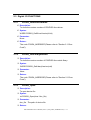
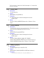
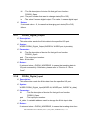
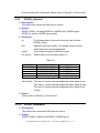
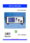
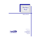
PIO-D56/D24
User Manual
Warranty
All products manufactured by ICP DAS are warranted against
defective materials for a period of one year from the date of
delivery to the original purchaser.
Warning
ICP DAS assume no liability for damages consequent to the
use of this product. ICP DAS reserves the right to change this
manual at any time without notice. The information furnished by
ICP DAS is believed to be accurate and reliable. However, no
responsibility is assumed by ICP DAS for its use, nor for any
infringements of patents or other rights of third parties resulting
from its use.
Copyright
Copyright 2003 by ICP DAS. All rights are reserved.
Trademark
The names used for identification only may be registered
trademarks of their respective companies.
PIO-D56/D24 User’s Manual (Ver.1.0, July.2007 , PMH-009-24 ) ----1
Tables of Contents
1.
Linux Software Installation ....................................................................... 3
1.1 Linux Driver Installing Procedure .....................................................................3
1.2 Linux Driver Uninstalling Procedure.................................................................3
2.
Static Libary Function Description........................................................... 4
2.1 Table of ErrorCode and ErrorString ...................................................................5
2.2 Function Descriptions .........................................................................................5
2.3 Digital I/O FUNCTIONS....................................................................................6
2.3.1
2.3.2
2.3.3
2.3.4
PIODA_GetDriverVersion.....................................................................6
PIODA_GetLibaryVersion.....................................................................6
PIODA_Open.........................................................................................6
PIODA_Close ........................................................................................7
2.3.5
2.3.6
2.3.7
PIODA_DriverInit..................................................................................7
PIODA_PortDirCfs................................................................................7
PIODA_Digital_Output .........................................................................8
2.3.8 PIODA_Digital_Input ............................................................................8
2.3.9 PIODA_IntInstall ...................................................................................9
2.3.10 PIODA_IntRemove................................................................................9
3.
PIO-D56/D24 Demo Programs For Linux ............................................... 11
3.1
3.2
3.3
3.4
Demo code “port.c”..........................................................................................11
Demo code “port_a.c”......................................................................................11
Demo code “int.c”............................................................................................12
Demo code “int2.c”..........................................................................................12
3.5 Demo code “int_a.c” ........................................................................................12
PIO-D56/D24 User’s Manual (Ver.1.0, July.2007 , PMH-009-24 ) ----2
1. Linux Software Installation
The PIO-D56/D24 can be used in linux kernel 2.4.X and 2.6.X. For Linux
O.S, the recommended installation and uninstall steps are given in Sec 1.1 ~
1.2
1.1 Linux Driver Installing Procedure
Step 1: Copy the linux driver “ixpio-0.20.3.tar.gz”(or the later driver version)
in the directory “NAPDOS\Linux” of the companion CD to the linux
host that you want to install driver.
Step 2: Decompress the tarball “ixpio-0.20.3.tar.gz”.
Step 3: Type `cd' to the directory containing the package's source code and
type ./configure' to configure the package for your system.
Step 4: Type `make' to compile the package.
Step 5: Type `./ixpio.inst' to install the PIO/PISO driver module and build
the device file “ixpioX” in the device directory “/dev” automatically.
1.2 Linux Driver Uninstalling Procedure
Step 1: Type `cd' to the directory containing the package's source code.
Step 2: Type `./ixpio.remove' to remove the PIO/PISO driver module.
PIO-D56/D24 User’s Manual (Ver.1.0, July.2007 , PMH-009-24 ) ----3
2. Static Libary Function Description
The static libary is the collection of function calls of the PIO-DIO cards for
linux kernel 2.4.x and 2.6.x system. The application structure is presented as
following figure. The user application program developed by C(C++) language
can call library “libpio.a” in user mode. And then static libary will call the module
ixpio to access the hardware system.
User's Application
Function Call into Libary
Development
Toolkit
Static library “libpio.a”
Services Call into Kernel-Mode
ixpio.ko (Device Driver)
Device Control
Hardware Devices
Figure 2.1
PIO-D56/D24 User’s Manual (Ver.1.0, July.2007 , PMH-009-24 ) ----4
2.1 Table of ErrorCode and ErrorString
Table 2.1
Error
Code
Error ID
Error String
0
PIODA_NOERROR
OK ( No error !)
1
PIODA_MODULE_NAME_GET_ERROR
Module name can't get
from file /proc/ixpio/ixpio
2
PIODA_DEVICE_DIO_INIT_ERROR
Initial digital I/O port error
3
PIODA_ACTIVE_PORT_ERROR
Select I/O port error
4
PIODA_PORT_DEFINED_ERROR
Port number out of range
5
PIODA_DIGITAL_OUTPUT_ERROR
Digital output error
6
PIODA_DIGITAL_INPUT_ERROR
Digital input error
7
PIODA_INT_SOURCE_DEFINED_ERROR
Interrupt source defined
error
8
PIODA_CONFIGURE_INTERRUPT_ERROR
Configure interrupt error
9
PIODA_ACTIVEMODE_DEFINED_ERROR
Defined Interrupt active
mode error
PIODA_ADD_SIGNAL_ERROR
Add
10
signal
condition
error
2.2 Function Descriptions
Table 2.2
Function Definition
WORD PIODA_GetDriverVersion(void);
WORD PIODA_GetLibaryVersion(void);
int PIODA_Open(char *dev_file);
WORD PIODA_Close(WORD fd);
WORD PIODA_DriverInit(WORD);
WORD PIODA_PortDirCfs(WORD, WORD, boolean);
WORD PIODA_Digital_Output(WORD, WORD, byte);
WORD PIODA_Digital_Input(WORD, WORD, WORD *);
WORD PIODA_IntInstall(WORD, HANDLE, WORD, WORD, WORD);
WORD PIODA_IntRemove(WORD, WORD);
PIO-D56/D24 User’s Manual (Ver.1.0, July.2007 , PMH-009-24 ) ----5
2.3 Digital I/O FUNCTIONS
2.3.1
•
•
•
•
2.3.2
•
•
•
PIODA_GetDriverVersion
Description:
To show the version number of PIO/PISO linux driver.
Syntax:
WORD PIODIO_GetDriverVersion(Void)
Parameter:
None
Return:
The code “PIODA_NOERROR”(Please refer to "Section 2.1 Error
Code").
PIODA_GetLibaryVersion
Description:
To show the version number of PIO/PISO linux static libary.
Syntax:
WORD PIODIO_GetLibaryVersion(void)
Parameter:
None
•
Return:
The code “PIODA_NOERROR”(Please refer to "Section 2.1 Error
Code").
2.3.3
•
•
•
•
PIODA_Open
Description:
To open device file.
Syntax:
int PIODIO_Open(char *dev_file)
Parameter:
dev_file : The path of device file
Return:
PIO-D56/D24 User’s Manual (Ver.1.0, July.2007 , PMH-009-24 ) ----6
The file descriptor of device file. If the file descriptor < 0, it means that
open device file failure.
2.3.4
•
•
•
PIODA_Close
Description :
To close device file.
Syntax :
Word PIODIO_Close(WORD fd)
Parameter :
fd : The file descriptor of device file that get from function
PIODIO_Open.
•
Return:
The code “PIODA_NOERROR”(Please refer to "Section 2.1 Error
Code").
2.3.5
•
•
•
•
2.3.6
•
•
•
PIODA_DriverInit
Description :
To allocates the computer resource for the device. This function must be
called once before applying other PIODA functions.
Syntax :
WORD PIODA_DriverInit(WORD fd)
Parameter :
fd : The file descriptor of device file that get from function
PIODIO_Open
Return:
The code “PIODA_MODULE_NAME_GET_ERROR”,
“PIODA_READ_EEPROM_ERROR”(only for PIO-DA16 device) or
“PIODA_NOERROR”(Please refer to "Section 2.1 Error Code").
PIODA_PortDirCfs
Description :
To change Digital I/O port. status(DI or DO)
Syntax :
WORD PIODA_PortDirCfs(WORD fd, WORD port, boolean io)
Parameter :
PIO-D56/D24 User’s Manual (Ver.1.0, July.2007 , PMH-009-24 ) ----7
fd
: The file descriptor of device file that get from function
PIODIO_Open.
port : The.port number that want to change status(DI or DO)
io : The value 0 means digital output. The value 1 means digital input.
•
Return:
If returned value < 0, it means that changing port status(DI or DO)
failure.
2.3.7
•
•
PIODA_Digital_Output
Description :
This subroutine sends the 8 bits data to the specified I/O port.
Syntax :
WORD PIODA_Digital_Output(WORD fd, WORD port, byte data);
•
Parameter :
fd : The file descriptor of device file that get from function
PIODIO_Open.
port : The.output port number.
data : 8 bits data.
•
Return:
If returned value = PIODA_NOERROR, it means that sending data to
I/O port successfully. Otherwise, please refer to "Section 2.1 Error
Code".
2.3.8
•
•
•
PIODA_Digital_Input
Description :
This subroutine reads the 8 bits data from the specified I/O port.
Syntax :
WORD PIODA_Digital_Input(WORD fd, WORD port, WORD *di_data);
Parameter :
fd
: The file descriptor of device file that get from function
PIODIO_Open.
port
: The.input port number.
di_data : A variable address used to storage the 8 bits input data.
•
Return:
If returned value = PIODA_NOERROR, it means that reading data from
PIO-D56/D24 User’s Manual (Ver.1.0, July.2007 , PMH-009-24 ) ----8
DI port successfully. Otherwise, please refer to "Section 2.1 Error Code".
2.3.9
•
•
PIODA_IntInstall
Description :
This subroutine installs the IRQ service routine.
Syntax :
WORD PIODA_IntInstall(WORD fd, HANDLE hisr, WORD signal,
WORD int_source, WORD activemode);
•
Parameter :
fd
hisr
:The file descriptor of device file that get from function
PIODIO_Open.
: Address of a Event handle. The handle function will be
called when the interrupt happened.
signal
: The number of signal is defined by user.
Int_source : Please refer to the following table 2.3.
Table 2.3
Card No.
PIO-D56/D24
Int_source
PIOD56_24_P2C0
PIOD56_24_P2C1
PIOD56_24_P2C2
PIOD56_24_P2C3
PIOD56_24_ALL_INT
Description
Enable P2C0
Enable P2C1
Enable P2C2
Enable P2C3
Enable All Int Source
activemode : The value 0 means interrupt happened when signal is low.
The value 1 means interrupt happened when signal is high.
The value 2 means interrupt happened when signal is low
or high.
•
2.3.10
•
Return:
Please refer to "Section 2.1 Error Code".
PIODA_IntRemove
Description :
This subroutine removes the IRQ service routine.
•
Syntax :
WORD PIODA_IntRemove(WORD fd, WORD sig_id)
PIO-D56/D24 User’s Manual (Ver.1.0, July.2007 , PMH-009-24 ) ----9
•
Parameter :
fd
: The file descriptor of device file that get from function
PIODIO_Open.
sig_id
•
: The number of signal is defined by user.
Return:
If returned value = PIODA_NOERROR, it means that sending data to
I/O port successfully. Otherwise, please refer to "Section 2.1 Error
Code".
PIO-D56/D24 User’s Manual (Ver.1.0, July.2007 , PMH-009-24 ) ----10
3.
PIO-D56/D24 Demo Programs For Linux
All of demo programs will not work normally if PIO/PISO linux driver would
not be installed correctly. During the installation process of PIO/PISO linux
driver, the install-scripts “ixpio.inst” will setup the correct kernel driver. After
driver(version 0.20.3 or the later driver version) compiled and installation, the
related demo programs and development library and declaration header files for
different development environments are presented as follows.
Table 3.1
Driver Name
Directory Path
File Name
Description
Include
piodio.h
PIO/PISO library header
lib
libpio.a
PIO/PISO static libary
ixpio-0.20.3
examples/piod56
examples/piod24
port.c
Digital input and output demo
port_a.c
DI and DO demo with libary
int.c
Interrupt demo
int2.c
Interrupt demo
Int_a.c
Interrupt demo with libary
3.1 Demo code “port.c”
This demo program is used to output data from port 1 and read data from
port 2, port 0.
3.2 Demo code “port_a.c”
This demo program coded by using the static library “libpio.a”. It is used to
output digital from port 1 and read data from port 0 port 2 .
PIO-D56/D24 User’s Manual (Ver.1.0, July.2007 , PMH-009-24 ) ----11
3.3 Demo code “int.c”
This demo program uses P2C0, P2C1, P2C2, P2C3 as interrupt source. The
interrupt will be triggered according to the argument “sig.bedge”(if value = 0x0f,
then the interrupt triggered at high signal and low signal) or “sig.edge”(if value =
0x0f, then interrupt triggered at high signal. Otherwise, the interrupt triggered at
low signal).
3.4 Demo code “int2.c”
This program configures driver to enable P2C0, as interrupt source. The
interrupt will be triggered when the signal is high.
3.5 Demo code “int_a.c”
This demo program coded by using the static library “libpio.a” to enable P2C0, as
interrupt source. The interrupt will be triggered when the signal is low.
PIO-D56/D24 User’s Manual (Ver.1.0, July.2007 , PMH-009-24 ) ----12