1
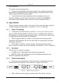
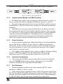
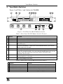
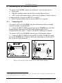
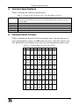
Kramer Electronics, Ltd.
USER MANUAL
Model:
VS-4228
8 Port RS-422 Matrix Switcher
Contents
Contents
1
2
3
3.1
Introduction
Getting Started
Overview
About RS-422
1
1
1
2
3.1.1
3.1.2
3.1.3
3.1.4
3.1.5
3.1.6
3.1.7
3.1.8
Signal Terminology
Standards
Bi-directional Signals
Communication Method via a DB9 Connector
Device Definition
Automatic Configuration
Port Definitions
More Than One Slave
2
2
2
3
3
3
3
4
4
4.1
Your Matrix Switcher
Connecting the VS-4228 Matrix Switcher
5
6
4.1.1
Connecting a PC
6
5
6
Technical Specifications
Communication Protocol
7
7
Figures
Figure 1: Bi-directional Signals I
Figure 2: Bi-directional Signals II
Figure 3: VS-4228 8 Port RS-422 Matrix Switcher
Figure 4: Connecting a PC without using a Null-modem Adapter
2
3
5
6
Tables
Table 1: Front Panel VS-4228 Matrix Switcher Features
Table 2: Rear Panel VS-4228 Matrix Switcher Features
Table 3: Technical Specifications of the VS-4228 Matrix Switcher
Table 4: VS-4228 Matrix Switcher Hex Table
5
5
7
7
i
Introduction
1
Introduction
Dedication by Kramer Electronics since 1981, to the development and
manufacture of high quality video/audio equipment, makes the Kramer line
an integral part of the finest production and presentation facilities in the
world. In recent years, Kramer has redesigned and upgraded most of the line,
making the best even better! The Kramer line of professional video/audio
electronics is one of the most versatile and complete available, and is a true
leader in terms of quality, workmanship, price/performance ratio and
innovation. In addition to our high quality switchers and matrices, we also
offer excellent distribution amplifiers, remote controllers, processors,
interfaces and computer-related products. Congratulations on purchasing your
Kramer VS-4228 8 Port RS-422 Matrix Switcher. This product is ideal for the
following typical applications:
Remote control of video and audio production studios
Live broadcast remote control
CCTV and other remote control applications
The package includes the following items:
VS-4228 8 Port RS-422 Matrix Switcher
Power cord
Windows 95/98/NT TM Kramer control software
Null-modem adapter
This user manual
2
Getting Started
We recommend that you:
Unpack the equipment carefully and save the original box and packaging
materials for possible future shipment
Review the contents of this user manual
3
Overview
The VS-4228 is an 8 port control matrix switcher that is RS-422 based, and:
Offers simple-to-connect automatic master/slave configuration
Includes a bright LED display showing the status of the matrix switcher
Recalls up to 15 configuration setups via the non-volatile memory
Is controllable via the front panel buttons, or remotely by RS-485 or
RS-232 serial commands transmitted by a touch screen system, PC, or other
1
Overview
serial controller
To achieve the best performance:
Connect only good quality connection cables, thus avoiding interference,
deterioration in signal quality due to poor matching, and elevated noise levels
(often associated with low quality cables)
Avoid interference from neighboring electrical appliances that may
adversely influence signal quality and position your Kramer VS-4228 in a
location free from moisture and away from excessive sunlight and dust
3.1 About RS-422
RS-422 control switchers differ substantially from video and audio switchers
in both design and in operation, as sections 3.1.1 to 3.1.8 describe.
3.1.1
Signal Terminology
Connections are between Master and Slave or Controller and Controlled
devices, rather than the regular In and Out or Source and Destination devices.
The difference is not merely one of semantics but a vital distinction when trying
to understand the concept of RS-422 technology
With a regular In and Out switcher, not only does the front panel have
separate In and Out buttons but the rear panel also has separate ports for input
and output connectors
With a Master and Slave control switcher, the front panel has separate
Master and Slave buttons but the rear panel has shared Master / Slave connectors
3.1.2
Standards
RS-422 meets 2 specific standards:
TIA/EIA-422-B, which defines the electrical specifications
SMPTE 207M, which defines the rules of exchanging information for
broadcast equipment (the protocol)
3.1.3
Bi-directional Signals
By using a pair of conductors, each signal travels in both directions via a
balanced line between Master / Slave devices, as Figure 1 illustrates:
Figure 1: Bi-directional Signals I
When a Master device changes position with a Slave device, the pins
2
KRAMER ELECTRONICS, LTD.
Overview
automatically change, as section 3.1.6 describes and as Figure 2 illustrates:
Figure 2: Bi-directional Signals II
3.1.4
Communication Method via a DB9 Connector
The Master unit usually sends a command to the Slave device via pins 3(+)
and 8(-) and the Slave device responds to the Master via pins 2(-) and 7(+)
Keep the communication path clear between the Master and Slave units in
both directions, as the Slave device must respond to a command transmitted by
the Master
If the Master receives no response from the Slave, the Master will cancel
the communication with the Slave machine and will sometimes flag a message:
no communication. For example, in video production when a special controller
(with play and rewind functionality) is the Master device, each command
transmitted to the Slave device must reach that Slave device and that Slave
device must respond, otherwise the Master device will disconnect
3.1.5
Device Definition
In many broadcast applications, different machines involved in production
can be either Slaves or Masters. Using a device as a Master means that the
device talks via pins 3 and 8 and listens via pins 2 and 7. In another setup, that
uses the same device as a Slave, this will mean that the device talks via pins 2
and 7 and listens via pins 3 and 8
For example, an edit controller always works as a Master. During an editing
session, a VTR may be the Slave to the edit controller. However, in a
duplication setup, the VTR may become a Master for a second VTR
3.1.6
Automatic Configuration
After connecting the DB9 connectors and cables between the controlled
units, the VS-4228 automatically configures which pins to use in the DB9
connector according to the assignment of each machine
3.1.7
Port Definitions
Modern equipment usually has only one connector, RS-422, which
functions as a Master as well as a Slave
Some older broadcast equipment contains 3 RS-422 connectors; RS-422-In,
RS-422-Out and RS-422-In/Out. You can only connect a Master to a RS-422-In
port and you can only connect a RS-422-Out port to a Slave. When connecting
to a RS-422-In/Out port the unit changes dynamically, automatically
3
Overview
reconfiguring the DB9 port pins to be either a Master or a Slave
3.1.8
More Than One Slave
Communication between one Master and one Slave is simple. However,
communication between one Master and several Slaves, for example, in
duplication applications, is more complicated
If all the Slaves were to respond simultaneously to a Master command, the
system would grind to a halt. To avoid such a situation, a special algorithm in
the VS-4228 dictates that the Master will receive only the response from the
highest priority slave1 with more than one Slave device. For example, in a setup
in which port # 7 is the Master, and ports # 5, # 3 and # 6 are Slaves, the
VS-4228 will only transmit to the Master the reply from port # 3 and will
discard all the other replies
Pay special attention: in broadcast applications, the most common reply
message from a Slave is the TIMECODE data, therefore, with the abovedescribed algorithm; the response will come from the lowest numbered Slave
1 The lowest numbered Slave device
4
KRAMER ELECTRONICS, LTD.
Your Matrix Switcher
4
Your Matrix Switcher
Figure 3 and Tables 1 and 2 define the VS-4228:
Figure 3: VS-4228 8 Port RS-422 Matrix Switcher
Table 1: Front Panel VS-4228 Matrix Switcher Features
#
1
2
3
4
Feature
Power Switch
MASTER Buttons
SLAVE Buttons
ALL Button
Function
Illuminated switch supplying power to the unit
Select 1 - 8 to connect between a SLAVE device and a MASTER device
Select 1 - 8 to connect between a MASTER device and a SLAVE device
Pressing ALL before pressing a SLAVE button, connects that SLAVE to all
MASTER devices
OFF Button
Pressing OFF after pressing a MASTER button disconnects that MASTER device
from the SLAVE devices. To disconnect all the MASTER devices, press the ALL
button and then the OFF button
STO Button
Pressing STO (STORE) followed by an MASTER button stores the current setting
RCL Button
Pressing the RCL (RECALL) button and the corresponding MASTER key recalls a
setup. The stored status blinks. Pressing a different MASTER button lets you view
another setup. After making your choice, pressing the RCL button again
implements the new status
SLAVE STATUS Labels identify a cross point between each SLAVE to which the MASTER
displayed below it is connected
MASTER STATUS 7-segment Display shows the selected MASTER switched to the SLAVE (alongside
the corresponding SLAVE label)
5
6
7
8
9
Table 2: Rear Panel VS-4228 Matrix Switcher Features
#
1
2
3
4
5
Feature
RS-422 Ports
CONTROL RS-485 Connector
CONTROL RS-232 IN Connector
CONTROL RS-232 OUT Connector
Power Connector with Fuse
Function
8 RS-422 bi-directional connectors
Connector for external RS-485 control (PINOUT: G, -, +)
Connect to the PC serial port
Connect to the RS-232 IN port of the next unit
AC connector enabling power supply to the unit
5
Your Matrix Switcher
4.1 Connecting the VS-4228 Matrix Switcher
To connect the VS-4228, connect the following1 to the rear panel ports:
Power cord
DB-9M Connector cables from the Slave and the Master devices
A PC via the null-modem adapter (when using the Kramer Control software
or other controller) if control via RS-232 is required
RS-485 terminal block cable if control via RS-485 is required
4.1.1
Connecting a PC
To connect a PC to the VS-4228, using the Null-modem adapter provided
with the machine (recommended):
Connect the RS-232 DB9 rear panel port on the VS-4228 unit to the Nullmodem adapter and connect the Null-modem adapter with at least 3
straightforward wires (pins 2, 3 and 5) to the RS-232 DB9 port on your PC
To connect a PC to the VS-4228, without using a Null-modem adapter:
Connect the RS-232 DB9 port on your PC to the RS-232 DB9 rear panel
port on the VS-4228 unit, as Figure 4 illustrates (depending on whether the PC
has a 9-pin or 25-pin connector)
Figure 4: Connecting a PC without using a Null-modem Adapter
1 Switch OFF the power on each device before connecting it to your VS-4228. After connecting your VS-4228, switch on its
power and then switch on the power on each device
6
KRAMER ELECTRONICS, LTD.
Technical Specifications
5
Technical Specifications
Table 3 includes the technical specifications:
Table 3: Technical Specifications of the VS-4228 Matrix Switcher
Connectors:
8 in/out RS-422 ports on DB-9 female connectors, fully compliant to the TIA/EIA-422-B standard
RS-232 control via DB-9F connector (RS-232 out on DB-9M connector), RS-485 on terminal
block assembly
Control:
Manual with pushbuttons on front panel, RS-485 and RS-232 serial interface
Dimensions:
19-inch (W), 7-inch (D) 1U (H) rack-mountable
Power Source:
VAC, 50/60 Hz, (115VAC, U.S.A.) 10VA
Weight:
2.2 kg. (4.88 lbs.) approx
Accessories:
Power cord, Windows ™ 95/98 control software, null modem adapter
6
Communication Protocol
Table 4 includes the Protocol 2000 hexadecimal codes (the protocol uses 4
bytes of information, data is at 9600 baud, no parity, 8 data bits and one stop
bit). Full details are available at our web site: www.kramerelectronics.com.
Table 4: VS-4228 Matrix Switcher Hex Table
M1
S1
S2
S3
S4
S5
S6
S7
S8
M2
M3
M4
M5
M6
M
M8
7
LIMITED WARRANTY
Kramer Electronics (hereafter Kramer) warrants this product free from defects in material and workmanship under the
following terms.
HOW LONG IS THE WARRANTY
Labor and parts are warranted for three years from the date of the first customer purchase.
WHO IS PROTECTED?
Only the first purchase customer may enforce this warranty.
WHAT IS COVERED AND WHAT IS NOT COVERED
Except as below, this warranty covers all defects in material or workmanship in this product. The following are not covered
by the warranty:
1.
2.
3.
Any product which is not distributed by Kramer, or which is not purchased from an authorized Kramer dealer. If you are
uncertain as to whether a dealer is authorized, please contact Kramer at one of the agents listed in the web site
www.kramerelectronics.com.
Any product, on which the serial number has been defaced, modified or removed.
Damage, deterioration or malfunction resulting from:
i)
Accident, misuse, abuse, neglect, fire, water, lightning or other acts of nature
ii)
Product modification, or failure to follow instructions supplied with the product
iii)
Repair or attempted repair by anyone not authorized by Kramer
iv)
Any shipment of the product (claims must be presented to the carrier)
v)
Removal or installation of the product
vi)
Any other cause, which does not relate to a product defect
vii)
Cartons, equipment enclosures, cables or accessories used in conjunction with the product
WHAT WE WILL PAY FOR AND WHAT WE WILL NOT PAY FOR
We will pay labor and material expenses for covered items. We will not pay for the following:
1.
2.
3.
Removal or installations charges.
Costs of initial technical adjustments (set-up), including adjustment of user controls or programming. These costs are the
responsibility of the Kramer dealer from whom the product was purchased.
Shipping charges.
HOW YOU CAN GET WARRANTY SERVICE
1.
2.
3.
To obtain service on you product, you must take or ship it prepaid to any authorized Kramer service center.
Whenever warranty service is required, the original dated invoice (or a copy) must be presented as proof of warranty coverage,
and should be included in any shipment of the product. Please also include in any mailing a contact name, company, address, and
a description of the problem(s).
For the name of the nearest Kramer authorized service center, consult your authorized dealer.
LIMITATION OF IMPLIED WARRANTIES
All implied warranties, including warranties of merchantability and fitness for a particular purpose, are limited in duration to
the length of this warranty.
EXCLUSION OF DAMAGES
The liability of Kramer for any effective products is limited to the repair or replacement of the product at our option. Kramer
shall not be liable for:
1.
2.
Damage to other property caused by defects in this product, damages based upon inconvenience, loss of use of the product, loss
of time, commercial loss; or:
Any other damages, whether incidental, consequential or otherwise. Some countries may not allow limitations on how long an
implied warranty lasts and/or do not allow the exclusion or limitation of incidental or consequential damages, so the above
limitations and exclusions may not apply to you.
This warranty gives you specific legal rights, and you may also have other rights, which vary from place to place.
NOTE: All products returned to Kramer for service must have prior approval. This may be obtained from your dealer.
This equipment has been tested to determine compliance with the requirements of:
EN-50081:
"Electromagnetic compatibility (EMC);
generic emission standard.
Part 1: Residential, commercial and light industry"
EN-50082:
"Electromagnetic compatibility (EMC) generic immunity standard.
Part 1: Residential, commercial and light industry environment".
CFR-47:
FCC Rules and Regulations:
Part 15: “Radio frequency devices
Subpart B – Unintentional radiators”
CAUTION!
Servicing the machines can only be done by an authorized Kramer technician. Any user who makes changes or modifications to
the unit without the expressed approval of the manufacturer will void user authority to operate the equipment.
Use the supplied DC power supply to feed power to the machine.
Please use recommended interconnection cables to connect the machine to other components.
8
KRAMER ELECTRONICS, LTD.
For the latest information on our products and a list of Kramer
distributors, visit our Web site: www.kramerelectronics.com,
where updates to this user manual may be found.
We welcome your questions, comments and feedback.
Safety Warning:
Disconnect the unit from the power supply before
opening/servicing.
Caution
Kramer Electronics, Ltd.
Web site: www.kramerelectronics.com
E-mail: [email protected]
P/N: 2900-002033 REV 3A