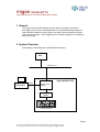
1
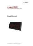
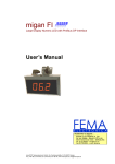
migan ModbusRTU
Large Display Numeric LED with Modbus RTU Interface
User’s Manual
Distribuidor en España :
FEMA ELECTRÓNICA, SA
Pol. Ind. Santiga – Altimira 14 (T14 N2)
08210 Barberà del Vallès – BARCELONA
Tel. 93.72.96004 – [email protected]
Fax 93.729.6003 – w w w .fema.es
microSYST Systemelectronic GmbH, Zur Centralwerkstätte 10, D-92637 Weiden, Germany
Tel. (+49- 961) 3 91 66-0, Fax (+49-9 61) 3 91 66-10, www.microsyst.de, [email protected]
migan ModbusRTU
Large Display Numeric LED with Modbus RTU Interface
Index
1
GENERAL
3
2
SYSTEM OVERVIEW
3
2.1
3
Device Configuration
TECHNICAL INFORMATION
5
3.1
Overall Specification
5
3.2
Device Start-Up
6
3.3
Display Control Via ModbusRTU
7
3.4
Connector Pin Assignments
3.4.1 External Connections
3.4.2 Internal LEDs and Switches
4
4
APPENDIX
10
10
11
14
4.1
Displayable Characters
14
4.2
Maintenance and Care
15
4.3
Declaration of Conformity
16
4.4
Guarantee
17
4.5
Versions Overview
18
Page 2
microSYST Systemelectronic GmbH, Zur Centralwerkstätte 10, D-92637 Weiden, Germany
Tel. (+49- 961) 3 91 66-0, Fax (+49-9 61) 3 91 66-10, www.microsyst.de, [email protected]
migan ModbusRTU
Large Display Numeric LED with Modbus RTU Interface
1 General
The large format numeric display can be used universally as a production display unit or as an information board. The modular design allows for
cost-effective models of various sizes, and with different character heights
and numbers of digits. Thus integration into existing equipment or systems is
easy and simple.
2 System Overview
The display is controlled with a ModbusRTU interface.
PLC
Modbus RTU
Gateway
PC for
configuration
RS232
migan Modbus RTU
Modbus RTU /
RS485
RS485
Controller
Board
Display Modules
Page 3
microSYST Systemelectronic GmbH, Zur Centralwerkstätte 10, D-92637 Weiden, Germany
Tel. (+49- 961) 3 91 66-0, Fax (+49-9 61) 3 91 66-10, www.microsyst.de, [email protected]
migan ModbusRTU
Large Display Numeric LED with Modbus RTU Interface
2.1 Device Configuration
Character Height:
60 mm
100 mm
150 mm
200 mm
250 mm
Number of Lines:
________
Number of Digits per Line:
1
2
3
4
11
12
13
14
5
15
Display Colour:
red
green
yellow
Dimensional Display:
Line 1: __________
Line 2: __________
Line 3: __________
Line 4: __________
Line 5: __________
Line 6: __________
Line 7: __________
Line 8: __________
6
7
8
View:
single sided
double sided
quadruple sided
Operating Voltage:
230 V / 50 Hz
110 V / 60 Hz
24 V DC
Protection:
IP40
IP54
IP65
Temperature Range:
0 to + 50 °C
9
10
-25 to + 50 °C
Housing dimensions: _________x_________x_________mm
Housing Colour:
Housing Material:
RAL _____________
Aluminium profile
Stainless steel
Sheet metal
Device Address:________
Page 4
microSYST Systemelectronic GmbH, Zur Centralwerkstätte 10, D-92637 Weiden, Germany
Tel. (+49- 961) 3 91 66-0, Fax (+49-9 61) 3 91 66-10, www.microsyst.de, [email protected]
migan ModbusRTU
Large Display Numeric LED with Modbus RTU Interface
3 Technical Information
3.1 Overall Specification
Display type:
Character height:
Digits:
Display colour:
Character set:
View:
Interface:
Operating voltage:
Power Consumption:
Housing:
Housing dimensions:
Mounting:
Protection:
Operating temp.:
Storage temperature:
7 segment LED
60 mm (2.36’’), 100 mm (3.94’’), 150 mm (5.91’’),
200 mm (7.87 ‘’), 250 mm (9.84’’)
2 to 15 digits
red, green, yellow
see chapter “Displayable Characters”
single, double or quadruple sided
ModbusRTU
230 V / 50 Hz, 110 V / 60 Hz or 24 VDC
60 mm (2.36’’) approx. 1.3 W per digit
100 mm (3.94’’) approx. 2.5 W per digit
150 mm (5.91’’) approx. 7.0 W per digit
200 mm (7.87’’) approx. 7.5 W per digit
250 mm (9.84’’) approx. 10.0 W per digit
industrial version, powder coated aluminium
see chapter “Device Configuration”
articulated arm, hanging mount bracket for wall mounting
IP54 or IP65
0 to +50 °C (optional -25 to +50 °C)
-25 to + 70°C
Page 5
microSYST Systemelectronic GmbH, Zur Centralwerkstätte 10, D-92637 Weiden, Germany
Tel. (+49- 961) 3 91 66-0, Fax (+49-9 61) 3 91 66-10, www.microsyst.de, [email protected]
migan ModbusRTU
Large Display Numeric LED with Modbus RTU Interface
3.2 Device Start-Up
Internal memory and function tests are performed at the large format display
during power-up.
The following parameters appear:
• Baud rate
• Parity
• Internal Address
These parameters do not have a meaning for the user and serve merely for
diagnostic purposes of the internal RS485 interface.
The ModbusRTU communication parameters are set via DIP-switches inside
the housing (see below) and will not be displayed!
Page 6
microSYST Systemelectronic GmbH, Zur Centralwerkstätte 10, D-92637 Weiden, Germany
Tel. (+49- 961) 3 91 66-0, Fax (+49-9 61) 3 91 66-10, www.microsyst.de, [email protected]
migan ModbusRTU
Large Display Numeric LED with Modbus RTU Interface
3.3 Display Control Via ModbusRTU
The display represents a ModbusRTU-Slave and is controlled by a ModbusRTUMaster (f.e. a PLC).
To change the display contents, the ModbusRTU-Master has to write to some
Registers. Therefore the commands “Force Multiple Registers” (function code
16d=10H) or “Read/Write Registers” (function code 23d=17H) can be used.
Here we assume that “Registers” are counted beginning at “0”. If your PLC starts
counting at “1” you may have to increase the register-address by 1!
The following data has to be written starting at register-address 0402H:
Register
0402H HIGH
LOW
0403H HIGH
LOW
0404H HIGH
LOW
0405H HIGH
LOW
0406H HIGH
LOW
0407H HIGH
LOW
0408H HIGH
LOW
0409H HIGH
LOW
040AH HIGH
LOW
Contents
P1 = decimal point byte 1 (for digits 1…5)
P2 = decimal point byte 2 (for digits 6…10)
P3 = decimal point byte 3 (for digits 11…15)
D1 = ASCII-code for digit 1
D2 = ASCII-code for digit 2
D3 = ASCII-code for digit 3
D4 = ASCII-code for digit 4
D5 = ASCII-code for digit 5
D6 = ASCII-code for digit 6
D7 = ASCII-code for digit 7
D8 = ASCII-code for digit 8
D9 = ASCII-code for digit 9
D10 = ASCII-code for digit 10
D11 = ASCII-code for digit 11
D12 = ASCII-code for digit 12
D13 = ASCII-code for digit 13
D14 = ASCII-code for digit 14
D15 = ASCII-code for digit 15
Remarks:
- Up to 15 digits are possible!
- It is not necessary to initialize unused digits!
- Registers 402H…40AH correspond to the “output data area” 204H…215H of
the used “HMS Anybus Communicator for Modbus RTU”.
Page 7
microSYST Systemelectronic GmbH, Zur Centralwerkstätte 10, D-92637 Weiden, Germany
Tel. (+49- 961) 3 91 66-0, Fax (+49-9 61) 3 91 66-10, www.microsyst.de, [email protected]
migan ModbusRTU
Large Display Numeric LED with Modbus RTU Interface
Display Data Positioning:
...
D1 is the 1st digit from the left side of the display.
…
Dn is the nth digit from the left side of the display (n=2…15).
Decimal Point Bytes:
If a decimal point needs to be set, the corresponding bit must be 1.
P1 (bin.) =
010XXXXX
Digit 5
Digit 4
Digit 3
Digit 2
Digit 1
P2 (bin.) =
010XXXXX
Digit 10
Digit 9
Digit 8
Digit 7
Digit 6
P3 (bin.) =
010XXXXX
Digit 15
Digit 14
Digit 13
Digit 12
Digit 11
So - if no decimal point needs to be set P1, P2 and P3 contain 40H each!
Page 8
microSYST Systemelectronic GmbH, Zur Centralwerkstätte 10, D-92637 Weiden, Germany
Tel. (+49- 961) 3 91 66-0, Fax (+49-9 61) 3 91 66-10, www.microsyst.de, [email protected]
migan ModbusRTU
Large Display Numeric LED with Modbus RTU Interface
Example for a ModbusRTU-Telegram=”Request” (in hex):
01
17
04 02 00 08 04 02 00 08 10
55 5F 5F 31 32 33 34 35 36 37 38 39 30 31 32 33
FC F8
01 : ModbusRTU node address
17 : ModbusRTU function code for “Read/Write Registers”
04 02 00 08 04 02 00 08 10 : Read/Write 8 Registers starting at 0402H
55 5F 5F 31 32 33 34 35 36 37 38 39 30 31 32 33 :
New Display Data = - all points set except at digit 2 and 4
- display “12345…”
FC F8 = CRC16(FFFFH)-Checksum
Remark: The ModbusRTU communication normally is done automatically by
the PLC! The user just has to set up the destination register addresses and
the “data part” of the telegram (point bytes and digit data)!
Page 9
microSYST Systemelectronic GmbH, Zur Centralwerkstätte 10, D-92637 Weiden, Germany
Tel. (+49- 961) 3 91 66-0, Fax (+49-9 61) 3 91 66-10, www.microsyst.de, [email protected]
migan ModbusRTU
Large Display Numeric LED with Modbus RTU Interface
3.4 Connector Pin Assignments
3.4.1 External Connections
9pol. Sub-D Female Connector “ModbusRTU”
Pin
1
2
3
4
5
6
7
8
9
Assignment
RS-232 TxD
RS-232 RxD
GND Bus
+5V Bus Out
RS-485 D0 (Rx/Tx-)
RS-485 D1 (Rx/Tx+)
Remark: Depending on DIP5 of the ModbusRTU-interface (see below) either
the RS232-pins or the RS485-pins may be used. The unused pins have to be
left open. Do not use a standard RS232-cable where all pins are connected.
Otherwise the ModbusRTU-interface may be destroyed!!!
9pol. Sub-D Male Connector “Configuration, RS232”
Pin
1
2
3
4
5
6
7
8
9
Assignment
RxD
TxD
GND
Remark: This connector should not be used by the customer! The configuration is already done by microSYST and must not be changed! Otherwise the
correct function of the display can not be guaranteed!
Page 10
microSYST Systemelectronic GmbH, Zur Centralwerkstätte 10, D-92637 Weiden, Germany
Tel. (+49- 961) 3 91 66-0, Fax (+49-9 61) 3 91 66-10, www.microsyst.de, [email protected]
migan ModbusRTU
Large Display Numeric LED with Modbus RTU Interface
7pol. Mains Plug (230 VAC)
Pin
1
2
(PE)
Assignment
L1
N
PE
3.4.2 Internal LEDs and Switches
1
2
3
4
5
6
LED
1 - Bus Error
2 - Bus Ready
3 – Processing
4 – HW Settings
5 - Subnet Status
6 - Device Status
State
Off
Description
Normal operation
Red
Off
Green
Red
Off
Bus error; CRC mismatch >10%
Not powered
Normal operation (bus ready)
Bus is off line (bus not ready)
Currently not processing query
Currently processing query
Normal operation
Not configured
Power off
Initializing and not running
Running
Stopped or subnet error, or timeout
Power off
Invalid or missing configuration
Initializing
Configuration OK
Green, flashing
Off
Red
Off
Green, flashing
Green
Red
Off
Alternating Red/Green
Green
Green, flashing
Page 11
microSYST Systemelectronic GmbH, Zur Centralwerkstätte 10, D-92637 Weiden, Germany
Tel. (+49- 961) 3 91 66-0, Fax (+49-9 61) 3 91 66-10, www.microsyst.de, [email protected]
migan ModbusRTU
Large Display Numeric LED with Modbus RTU Interface
ModbusRTU
Node Address
Node Address
(reserved)
*1
2
…
126
127
* = Factory-Setting
DIP1
OFF
OFF
OFF
…
ON
ON
DIP2
OFF
OFF
OFF
…
ON
ON
DIP3
OFF
OFF
OFF
…
ON
ON
DIP4
OFF
OFF
OFF
…
ON
ON
DIP5
OFF
OFF
OFF
…
ON
ON
DIP6
OFF
OFF
ON
…
ON
ON
DIP7
OFF
ON
OFF
…
OFF
ON
ModbusRTU
Baudrate
Baudrate
(reserved)
1200 baud
2400 baud
4800 baud
9600 baud
* 19200 baud
38400 baud
57600 baud
* = Factory-Setting
DIP8
OFF
OFF
OFF
OFF
ON
ON
ON
ON
DIP1
OFF
OFF
ON
ON
OFF
OFF
ON
ON
DIP2
OFF
ON
OFF
ON
OFF
ON
OFF
ON
ModbusRTU
Parity & Stop Bits
Parity
(reserved)
* No parity, 2 stop bits
Even parity, 1 stop bit
Odd parity, 1 stop bit
* = Factory-Setting
DIP3
OFF
OFF
ON
ON
DIP4
OFF
ON
OFF
ON
ModbusRTU
Physical Interface
Interface Type
RS232
* RS485
* = Factory-Setting
DIP5
ON
OFF
Page 12
microSYST Systemelectronic GmbH, Zur Centralwerkstätte 10, D-92637 Weiden, Germany
Tel. (+49- 961) 3 91 66-0, Fax (+49-9 61) 3 91 66-10, www.microsyst.de, [email protected]
migan ModbusRTU
Large Display Numeric LED with Modbus RTU Interface
Important note:
To change the setting of the DIP-switches obey the following order:
- disconnect the power supply
- open the housing
- open the dip switch protection cap (carefully - using a little srew driver)
- set the dip switches as desired
- close the dip switch protection cap
- close the housing
- reconnect the power supply
While the housing is open power may only be applied by qualified personnel and nothing has to be touched inside the housing at this time!
Otherwise electrical shock and danger to life may happen! Please be
careful!
Page 13
microSYST Systemelectronic GmbH, Zur Centralwerkstätte 10, D-92637 Weiden, Germany
Tel. (+49- 961) 3 91 66-0, Fax (+49-9 61) 3 91 66-10, www.microsyst.de, [email protected]
migan ModbusRTU
Large Display Numeric LED with Modbus RTU Interface
4 Appendix
4.1 Displayable Characters
The data bytes are ASCII-coded.
0010
0011 0100 0101 0110 0111
Lower Higher 0000 0001
+
)
0
1
2
3
4
5
6
7
0000 0
“Blank”
0001
1
0010
2
0011
3
0100
4
0101
5
0110
6
0111
7
1000
8
1001
9
1010
A
1011
B
1100
C
1101
D
1110
E
1111
F
Page 14
microSYST Systemelectronic GmbH, Zur Centralwerkstätte 10, D-92637 Weiden, Germany
Tel. (+49- 961) 3 91 66-0, Fax (+49-9 61) 3 91 66-10, www.microsyst.de, [email protected]
migan ModbusRTU
Large Display Numeric LED with Modbus RTU Interface
4.2 Maintenance and Care
Observe the following instructions in order to assure best possible performance of the display:
•
Make sure that the housing can be opened for adjustment and maintenance even after the display has been installed. Allow for adequate clearance at the back, front and top of the display unit in order to allow for sufficient ventilation (if vent slots are included).
•
Display quality is impaired by direct illumination with bright light sources
and/or direct sunlight.
•
The display must be switched off before cleaning.
•
Protect the display from excessive humidity, extreme vibration, direct
sunlight and extreme temperatures. Non-observance may lead to malfunctioning or destruction of the device. Under certain circumstances electrical shock, fire and explosion may occur as well. Information concerning
allowable ambient conditions, including recommended temperature
ranges, can be found in the chapter entitled “Technical Information”.
•
The display may not be placed into service if the device and/or the power
cable are known to be damaged.
•
Do not attempt to repair the device yourself. The guarantee is rendered
null and void if the device is tampered with by unauthorised persons.
Page 15
microSYST Systemelectronic GmbH, Zur Centralwerkstätte 10, D-92637 Weiden, Germany
Tel. (+49- 961) 3 91 66-0, Fax (+49-9 61) 3 91 66-10, www.microsyst.de, [email protected]
migan ModbusRTU
Large Display Numeric LED with Modbus RTU Interface
4.3 Declaration of Conformity
microSYST Systemelectronic GmbH, Zur Centralwerkstätte 10,
92637 Weiden, Germany
does hereby declare that the product described in this user’s manual,
“migan”
to which this declaration makes due reference,
is in compliance with the following standards or normative documents:
Interference emission: generic standard EN 50081 - 2, issued July 1993
Product standard: EN 55011; group 1/2; class A, issued March 1991
Limit values identical to EN 55022
Interference immunity: generic standard EN 50082 - 2, issued March 1995
Basic specification per table
In accordance with regulations specified by guideline 89/336/ EWG (and
EMVG).
Weiden, 22 November 1999
microSYST Systemelectronic GmbH
Page 16
microSYST Systemelectronic GmbH, Zur Centralwerkstätte 10, D-92637 Weiden, Germany
Tel. (+49- 961) 3 91 66-0, Fax (+49-9 61) 3 91 66-10, www.microsyst.de, [email protected]
migan ModbusRTU
Large Display Numeric LED with Modbus RTU Interface
4.4 Guarantee
The display is guaranteed for the duration specified in the “General Terms and
Conditions” regarding manufactured products and services rendered for the
electrical industry period against defects which existed at the time the device
was delivered to the buyer.
The device is subject to technical change without notice. Errors and omissions
are excepted. No claims can be honoured for the shipment of a new product.
The buyer is required to make notification of defects within 2 weeks after identification of such. Non-observance of notification requirements is equated with
acceptance of the defect.
Defects and their symptoms must be described as accurately as possible in
order to allow for reproducibility and elimination. The buyer must provide for
access to all required and/or useful information regarding defects at no
charge, as well as to the affected devices, and must make all of the required
data and machine time available free of charge.
The guarantee does not cover defects which result from non-observance of
the prescribed conditions of use, or from improper handling.
If the device has been placed at the disposal of the buyer for test purposes
and has been purchased subsequent to such testing, both parties agree that
the product is to be considered “used” and that it has been purchased “as is”.
No guarantee claims may be made in such cases.
The “General Terms and Conditions” regarding manufactured products and
services rendered for the electrical industry apply as well.
Page 17
microSYST Systemelectronic GmbH, Zur Centralwerkstätte 10, D-92637 Weiden, Germany
Tel. (+49- 961) 3 91 66-0, Fax (+49-9 61) 3 91 66-10, www.microsyst.de, [email protected]
migan ModbusRTU
Large Display Numeric LED with Modbus RTU Interface
4.5 Versions Overview
Version
Date
1.00
1.01
29.11.07
20.12.07
Remark, Description
Kreuzer: Document created
Nickl: Revised
Certified per DIN EN ISO 9001:2000.
Page 18
microSYST Systemelectronic GmbH, Zur Centralwerkstätte 10, D-92637 Weiden, Germany
Tel. (+49- 961) 3 91 66-0, Fax (+49-9 61) 3 91 66-10, www.microsyst.de, [email protected]