1
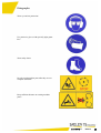
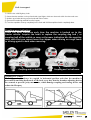
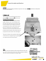
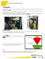
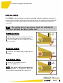
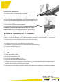
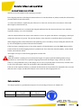
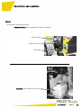
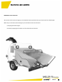
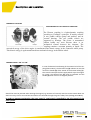
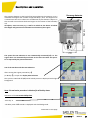
TECHNICAL MANUAL SOMMAIRE CONFIRMATION OF CONFORMITY ATTENTION GUARANTEE INVENTION PATENT PREFACE LOCATION OF THE SERIAL NUMBER SAFETY INFORMATION PICTOGRAMS SAFE TRANSPORTATION GENERAL DESCRIPTION OPERATION OF FEED ROLLER TOWING A VEHICULE CHECK BIFORE START STARTING INSTRUCTIONS DURING SHREDDING STOPPING BIO LUBRICANT RECOMMENDED AND CAPACITY LUBRICANTS MAINTENANCE INTERVALS LUBRICATION POINTS OIL LEVEL TENSION OF THE METAL BELT VERIFICATION BELT AND SLIDING PLATE AIR INLETS OF THE ROTOR DISASSEMBLY TO REPLACE BLADES AND HAMMER INSERTS DISASSEMBLY TO CHECK THE COUNTERBLADES ADJUSTMENT OF THE ROTOR BELTS MAINTENANCE OF THE HYDRAULIC COUPLING ADJUSTMENT OF THE BRAKES ENGINE START SWITCH PILOT SYSTEM HYDRAULIC AND DIESEL TANKS SAFETY CAPS EMERGENCY STOPS INDUCTIVE SENSOR AND FUSE HYDRAULIC COUPLER CO2 REDUCTION (option) DISCHARGE CHUTE GENERAL PROBLEM-SOLVING PROBLEM-SOLVING CO2 RÉDUCTION (option) SPECIFICATIONS HYDRAULIC COUPLING HYDRAULIC SCHEDULE ELECTRICAL CIRCUIT MOTOR ELECTRICAL CIRCUIT MACHINE 4 5 6 7 8 9 10 - 12 13 - 15 16 17 - 19 20 21 21 22 23 24 25 26 27 28 - 30 31 32 33 33 34 - 35 36 37 38 39 40 41 - 50 51 52 53 54 55 56 - 58 59 60 - 61 62 63 64 65 66 - 68 69 - 70 COBRA75DS 2014-09-22 3 DECLARATION OF CONFORMITY LA SOCIETE TS industrie Weserstrasse 2 47506 NEUKIRCHEN-VLUYN Tél : +49(0)2845 9292-0 - Fax : +49(0)2845 9292-28 HEREBY DECLARE THAT THE MACHINE: Trade Name: TS Industrie Type : GS/COBRA75DS Engine performance: 56 kW Technical documentation held by Mathieu Willerval. is in conformity with the following European Directives: - 2006/42/EC Directive „Machinery“ - 2004/108/EC Directive „Electromagnetic compatibility“ - 97/68/EC Directive „Emissions“ - 2000/14/EC Directive „Noise emissions“ Conformity evaluation procedure concerning directive 2000/14/CE Annex V. Power at 2600 rpm Measured sound pressure level Guaranteed sound pressure level (EVA) 56 Kw 124 dBA 126 dBA Reference of the applicable harmonised standards: - EN 13525/A2 RONCHIN, June 02, 2014 Mathieu Willerval ( Production Manager TS Industrie ) COBRA75DS 2014-09-22 4 Attention! Before our machines are delivered they pass a tight quality control in the works. Given that we no longer have a bearing on the machine after it leaves the works, the dealer has to perform another check before the delivery to the end customer. The following is to be checked: - Exterior damages produced by transport etc. - Tight seat of all screw and hose connections - Filling level of oil, water and fuel - Complete functional control of all parts This control is to be confirmed with stamp and signature on the Machine Delivery Document. If the fully completed and signed delivery document is not returned there is no right for warranty! Furthermore, it is required to check all screw connections for tight seat and the laid hoses for marks of abrasion! Agree a date for this directly with your customer. Regular inspections according to the operating manual are to be met! Controlled quality – an important step towards customer satisfaction! Play your part! COBRA75DS 2014-09-22 5 Guarantees Processing of warranty claims Warranty claims according to the General Business Terms of the manufacturer are valid for the period of 1 year starting with the day of delivery. Determinative for the moment of the transfer of risk is the date written in the Machine Delivery Document. As a matter of principle, warranty claims are to be announced to the supplying franchised dealer. For the preservation of evidence, all parts of the delivered machine covered by this have always to be stored unchanged until the final processing of the warranty claim brought to notice. Technical modification at machines and/or parts thereof will result in loss of any and all right of warranty claims. The same is applicable in case of inappropriate treatment or use of lubricants and spare parts or accessories not approved by the manufacturer. Transport damages and damages cause by usual wear after commissioning of the machine do not create any warranty claims. The delivered machine has to be subjected to the obligatory check and inspection intervals specified in the enclosed maintenance schedule. If the obligatory visual check and inspections schedule is not complied with, any and all warranty claims become void. Another requirement for a valid warranty claim is the presentation of a complete proof about the executed obligatory visual checks and inspections. All warranty and maintenance works are only allowed to be carried out by a specialist dealer authorised by TS Industrie. It is pointed out that warranty works exceeding an amount of 150.00 € is unconditionally to be agreed with TS Industrie and authorised by TS Industrie. In this case, the manufacturer reserves the right that he carries out the repair. Prerequisite for the assertion of a warranty claim is the return of the fully completed and signed Machine Delivery Document. Modifications on the equipment and programming of the electronic system are prohibited because these might have a negative effect on the operational safety and life time of the machine. DO NOT FORGET TO REGISTER THE WARRANTY, OTHERWISE IT WILL BECOME VOID www.ts-industrie.eu COBRA75DS 2014-09-22 6 PATENT FOR INVENTION Intellectual property law-Books VI GRANTING DECISION The General Manager of the National Institute of industrial property has decided that invention patent # ##-##### the text of which is appended shall be delivered to: SAELEN S.N.S. Company - FR The delivery produces its effects for a period of twenty years starting on the date of deposit of the application, under reserve of payment of the annual royalties. Mention of the delivery is made in the Official Bulletin of industrial property ###/## of ##:##:## (publication # # ### ###). COBRA75DS 2014-09-22 7 Preface We thank you very much for deciding to purchase an universal chipper from TS Industrie. Your universal chipper was manufactured with utmost care and high quality standards. In order to meet these requirements also for the mostly professional applications, we kindly ask you to diligently read this operating manual and to comply especially with the warning and maintenance information. Only if complying with all maintenance works within the specified maintenance intervals we can concede the full manufacturer’s warranty for your universal chipper from TS Industrie. The operating manual includes several models such that in the introduction is explained how to orient yourself with the help of small pictographs. COBRA75DS 2014-09-22 8 Location of the serial number For any spare parts order or a question regarding technical information have always the serial number of your COBRA 75 at hand. The serial number is located as shown in the image. It does always have five- or six-digit number. Serial number Do not state the number from the type plate of the trailer. COBRA75DS 2014-09-22 9 Safety instructions 1. The machine is only allowed to be used according to the operating manual! 2. In case of machines with engine also the operating instructions of the engine are to be observed. 3. Folding the intake extension up (as far as present) is only allowed after standstill of the rotor. 4. Maintenance, cleaning and setting works as well as the removal of protective devices are only allowed after the engine is shut down, the ignition switched off, the drive decoupled and the tools immobile. Remove the ignition key such that unintended start is impossible. 5. Prior to operation it is required to remove foreign matters, e.g. ferrous parts, stones etc. 6. After maintenance or repair it is to be checked if all protective devices are mounted. 7. The wood chipper is not allowed to be operated in closed spaces because of the risk of intoxication. 8. The rotor must not be uncovered before it has reached standstill. That is to say, the propulsion engine (tractor) is parked and the ignition is in 0-position. 9. The machine operator is responsible that no third persons are staying in the working and danger area. 10. For repairs it is to be observed to use approved original spare parts only. 11. Only persons of over 18 years are allowed to operate the wood chipper. 12. Safety shoes and tight fitting clothes, work gloves with tight gauntlets as well as ear protection and goggles are to be used. COBRA75DS 2014-09-22 10 13. For transporting the wood chipper it must be moved into transport position. A) Fold the hopper (as far as present) up and check if the locking device is engaged. B) Move the wood chipper into transport position an check if the safety pin has engaged. C) Turn the ejection channel such that it does not jut laterally out over the machine. D) If necessary lift all parking sustainers. 14. When driving on public roads the lighting must correspond to the Highway Code. 15. For work, the wood chipper must be parked stable. 16. a) Single-axle machines with engine are attached to tractor vehicles, and the parking brake is applied as far as present. In case of machines without brakes it is required to push the supplied chocks under the wheels. b) For operation without tractor vehicle it is required to lower the parking sustainers (front and rear). 17. For safety reasons a minimum distance of 10 metres should be kept from the machine. The expulsion must always be directed away from the operating personnel. 18. Only after the engine is shut off and the rotor is standing still, it is allowed to reach with the hands into the infeed mouth. 19. The admissible hydraulic operating pressure set ex works is not allowed to be changed. 20. Only trunks up to a diameter of 16 cm are allowed to be processed. 21. The hydraulic system is to be competently checked every year. The hydraulic hoses are to be replaced after 5 years. 22. During feed of the wood chipper do not reach into the feed hopper. Congestions are to be removed in a safe manner (shut the engine down, use an aid). For pushing in short pieces or shrubbery material do only use solid wooden rods or other aids made of wood. Our wood chippers are designed only for manual feed. Do not use mechanical resources (gripper) for feeding the machine. Do not move in the area of the expulsion. COBRA75DS 2014-09-22 11 23. Carry out an functional check every day before starting the machine, especially of the safety equipment (trailer coupling, gear linkage, shifting block, cut-off switch on the hoods in case of the M version etc.). Chipping knives and counter-knives are also to be checked for proper functioning and tight seat. 24. Prior to starting the machine the operator must be trained in detail. 25. The rotor must not be uncovered before standstill and the engine is switched off. 26. Danger because of flying off pieces. It is to be observed that also in the operating range pieces such as wood chips might fly out of the hopper area. Body protection is always to be used. Operation is to be carried out lateral of the hopper. 27. Note for all machines with engine: The inclination of the engine during operation (driving) must amount to max. 25°. In case of reduced oil level the lubrication of the engine is not ensured even at 25°! 28. Caution when parking the machine on a slope. The machine operator has to ensure that the machine is safely stationed for the time of the work. 29. After connecting the machine to the tractor vehicle, remove and store the support wheel. 30. The machine must only be fed with wood. Ensure that no stones or metal objects enter the machine. 31. The machine must not be used for transporting material or persons. 32. The machine must not be used for pushing or towing. 33. Battery acid is a caustic fluid. Therefore any contact with eyes, skin and clothes must be avoided. In case of contact rinse all affected areas with water and go see a doctor, if required. 34. Always disconnect the battery before any work on the electric installation. 35. Only trained personnel is authorised to carry out these works. The execution of all installation and removal works as well as special maintenance works is reserved for an authorised specialist dealer. 36. Pay attention that you are not drawn into the infeed roller with the clothes. 37. Regularly clean the lateral skirt such that it remains transparent. COBRA75DS 2014-09-22 12 Pictographs Wear eye and ear protection! Use protective gloves with specially tight gauntlets! Wear safety shoes! Do only touch machine parts after they are at a complete standstill! Keep sufficient distance to rotating machine parts! COBRA75DS 2014-09-22 13 Pictographs While the drive is running never open and remove protective devices! Read the operating manual before start-up! Do not stay in the area of the expulsion if the machine is running! Hazard area! Shut down the engine and remove the key prior to any maintenance and repair work! Caution! Entanglement. Never reach into the infeed hopper while the engine is running. Fill the fuel tank with diesel. COBRA75DS 2014-09-22 14 The machine is operated with hydraulic oil HV46. Lubrication points The sound level of the working machine is not the value of the standard level on the sticker. Moving direction commands for the conveyor belt Material chipping (forward max. speed) Stopping rotation of the infeed rollers Loosening material (backwards) COBRA75DS 2014-09-22 15 Safe transport 1) 2) 3) 4) 5) Observe the valid Highway Code. Ensure that the machine is always fitted with signal lights, which are clean and visible for other road users. Reduce speed when driving on rural roads and unlevel routes. Remove all remaining material from the hopper. Turn the expulsion chimney completely to the front and fold the expulsion hatch completely down. Coupling wear indication: Check the wear indication each time the machine is hooked up to the tractor vehicle. Acquire the habit to replace the coupling dog and / or coupling ball of the vehicle as soon as the wear indication hits the negative area, such that you cannot loose the chipper when driving on rough roads or driving against a kerb when reversing. Coupling and / or ball OK Coupling and / or ball worn Coupling to a vehicle: The chipper should always be coupled in horizontal position such that the machine is prevented from tilting backwards AND check every day that the drawbar adjusting devices are secured to prevent jerky movements, which damage coupling and towing device and reduce the life span. COBRA75DS 2014-09-22 16 General description and functions DESCRIPTION OF THE MACHINE The chipper COBRA75 TS Industrie is designed for chipping branches up to a diameter of 7,87 inchs. The machine consists of the following main components: (A) : Frame (B) : Chipping unit (C) : Engine and drives (D) : Expulsion chimney (E) : Noise insulation hoods (F) : Conveyor metallic belt COBRA75DS 2014-09-22 17 General description and functions A. Frame The frame is used for allocating the different components of the chipper COBRA and allows an independent movement of the machine. B. Chipping unit The unit consists of one infeed hopper (1), one conveyor belt (2), one infeed roller (3) and one rotor. Conveyor belt and infeed roller: They transport the chipping material at constant speed in direction rotor. An anti-blocking system disconnects the infeed if the speed of the rotor falls below the minimum speed (chipping unit jammed) and automatically connects again after the speed of the rotor is sufficient for correct chipping work. The infeed can turn into both directions (forward and backwards) when using the yellow and the black button (4) located on the left side of the infeed hopper . The speed of rotation can be matched to the diameter of the material to be chipped using the regulating screw (4) on the left side of the rear hood. Rotor: The rotor is the main component of the machine and has the task to chip the material coming from the infeed roller. After the engine accelerates, the rotor connects and rotates at a constant speed. COBRA75DS 2014-09-22 18 General description and functions C. Engine and drives The diesel engine is located above the chipping unit. It supplies the required energy for the drive of the rotor and the hydraulic oil pump (1). The machine is driven by a 3-cylinder diesel engine with an output of 75 HP at 2600 rpm. Further information regarding the engine can be taken from the manual of the manufacturer. The rotor is driven via the output shaft, the centrifugal clutch with belt pulley (2) and 5 V-belts. The hydraulic pump is connected to the diesel engine and drives the hydraulic motors of the infeed rollers. D. Expulsion channel This expulsion channel expulses the chipped material. The upper part can be swivelled by 180° in horizontale position. The expulsion hatch can be adjusted in vertical position. Caution: When connecting the wood chipper residual chips can be expulsed. Two electric switches disconnects the engine and prevents a restart if the expulsion chimney is open towards the rotor. Adjustment range Danger range Optimum range of rotation E. Hood The engine hood protects all movable parts of the machine and ensures safe working for the operator. A fuse stops the diesel engine and prevents a restart as soon as the engine hood is opened. COBRA75DS 2014-09-22 19 General description and functions MATERIAL INFEED The COBRA is fitted with an electrically controlled hydraulic distributor, which is activated with two buttons at the rear of the infeed hopper for running forwards and backwards, and with a red control rod for disconnection of the infeed roller and the conveyor belt. Note: The engine has to run at max. speed for making the conveyor belt and the infeed roller turn. FORWARDS MODE: 1. Move the red control rod back such that the infeed roller moves to forward motion. 2. Push the yellow button to make the roller move forwards. STOP THE INFEED: 1. Push the red control rod to make the infeed stop. BACKWARDS MODE: 1. Move the red control rod back 2. Push the black button. NOTE: The infeed can be switched directly from forwards to backwards and vice versa without operating the control rod. COBRA75DS 2014-09-22 20 HITCH-UP TO THE VEHICLE The machine is hitched up to the vehicle as follows: Adjust the shaft with the crank handle to the height of the trailer coupling of the tractor. Wind the stabilising wheel up using the crank handle until the ball coupling is higher than the ball. Push the ball coupling above the ball and wind the stabilising wheel down with the crank handle until the coupling clearly engages. Check if the ball coupling is correctly engaged! Insert the safety cable and connect the plug. Wind the stabilising wheel completely up and secure the wheel with the cotter pin in upper position. Check function of the lighting installation. Ensure that the indication on the coupling is in the green area (see page 16). CHECKS PRIOR TO INITIAL START-UP OF THE MACHINE Every operator has to read and understand the provisions, and has to observe all safety measures included in this chapter. A list with the checks for initial start-up is available to the operator. These checks have to be carried out for safety reasons to ensure the safe and efficient operation of the chipper. The following points are to be checked before using the machine: 1. The machine is sufficiently lubricated as indicated in the operating manual? 2. Check the following filling levels: Engine oil Coolant Fuel 3. Check the hydraulic oil level. 4. Check that the air filter is clean. 5. Check that the engine radiator is clean. 6. Ensure that all hoods are closed and locked. 7. The machine must not be operated in confined spaces. Risk of intoxication because of the diesel engine exhaust gases and dust generation by the chipper. 8. The expulsion channel and the expulsion hatch are only allowed to be adjusted by an authorised operator. COBRA75DS 2014-09-22 21 Operation and version I M P O R TA N T ! Operate the device only with Non-Road fuels or customary diesel fuel. By no means use fuel oil. ATTENTION! If the machine has difficulties in milling the material and has to be switched off, do not start the engine again before having remedied the cause and removed the material from the rotor!!! START-UP Before each start-up ensure that the machine is standing stable on solid ground and that the parking brake is engaged. 1) Check if the cover on the chimney is open. 2) Turn the key to connect the ignition. 3) Start the engine after approx. 30 seconds as soon as the Pilot System opens the display. - If the engine is cold the message Temperature too low appears. (See page XX if the engine stops immediately again and the message “slip error“ is indicated in the Pilot System.) 4) Press key 1, 2 or 3 (see also page 43). The engine runs idle until having reached the minimum operating temperature. Minimum operating temperature is reached: In field 1 is activated the symbol and the engine accelerates to working speed. As soon as the engine has reached working speed, the message Press start appears together with a Smiley. 5) Press the yellow key at the feed table to connect feed rollers / conveyor belt. 6) Now the work can be started. In case of overheat the engine power drops (not the speed) at first drops by 20%. In this case check radiator and cooling liquid level, otherwise the engine power drops by another 50% and it is no longer possible to use the machine. COBRA75DS 2014-09-22 22 Materia l inf eed and o peration INSTRUCTIONS FOR CHIPPING Watch out for solid foothold of the operating personnel! Place chipping material on the hopper bottom and move it with the thicker en (trunk) towards the infeed rollers (chamfer the thick end of the trunk). As soon as the material is captured by the rollers move to the side, because due to unevenness of the trunk there might be material kick-out. The captured material now is automatically chipped and hurled into the direction (distance) into which the expulsion chimney was set to beforehand. After the material infeed from time to time attention is also to be paid to the thrown out chippings, and maybe readjust the direction of ejection. The ejection distance of the material is controlled with the ejection hatch. When chipping splints, barks and brush-wood splintering can be avoided by always feeding the material sideby-side and lengthwise positioned into the infeed channel. If the feed stops (jamming because of too much material or forked branches), press the black button (rollers rotate backwards) and the chipping material is pushed back. Now reduce the material quantity, cut the forked branch, and restart the infeed. The hopper can only be cleaned using appropriate wooden aids. Caution: While the machine is running do not reach into the hopper! If required, push the kindling further using a wooden slat or wood slider! Never push the chipping material into the hopper using a metal rod or metal slider! It is also prohibited to stay in the danger area! In case of especially thick or hard wood, it makes sense to slow down the engine, reduce the speed until it has reached the rated speed. If the area of the expulsion chimney is jammed, the hood must not be opened before standstill of the rotor and shut-down drive engine, and then the material can be removed with an appropriate tool. Noise emission The chipper produces a guaranteed sound power level according to Directive le 2000/14/EC : Model COBRA Sound power level EVA [dB] 126 Sound pressure level [dB(A)] 124 COBRA75DS 2014-09-22 23 Materia l inf eed and o peration SHUT-DOWN 1. Have the chipper run for some minutes empty for removing the residual material behind the infeed roller in the chipper to prevent that the rotor becomes jammed in the next application, and the message "SLIP ERROR" is indicated (see page 45). 2. For stopping the infeed roller move the control rod forward. 3) Press again the key of the selected area 1, to switch the engine to idle running again. Let the engine run idle for approx. 10 seconds for temperature compensation in the turbocharger. 4) Turn the key on the control unit to switch the ignition off. COBRA75DS 2014-09-22 24 Mainte nance BIODEGRADABLE LUBRICANTS FOR REDUCING ENVIRONMENTAL POLLUTION Just by their function, the chippers from TS Industrie are used as a solution for the sustainable development for the production of compost, mulch and wood chips. TS Industrie chippers are often used in woods, parks, landmarks, in the proximity of lakes and rivers, where leaks and hydraulic fluids signify a risk for the environment. Therefore, the company TS Industrie contributes to the environmental protection by supplying their machines with biodegradable high performance lubricants. Corresponds to the agricultural Directive 2006/11/EG. Advantage of biodegradable lubricants: - No risk for the environment - Increase biodegradability - Not toxic (based on rapeseed and sunflower oil) - Regenerative - Very high viscosity - Excellent wear and anticorrosive properties - Increased safety for the user - Increased duration of the components - Reduced volatility properties COBRA75DS 2014-09-22 25 Mainte nance SAFETY INSTRUCTIONS 1. Securely park the machine, remove the contact key and wait until the standstill of all mobile parts before starting the maintenance and repair works. 2. After termination of the maintenance works ensure that all protective devices are properly mounted and are operative. All machines pass a test-drive before leaving the works. On delivery the hydraulic tank is filled up to the upper mark of the sight-glass with hydraulic oil. The filter has to be replaced after 150 operating hours. Thereafter, the replacement takes place according to the maintenance schedule. The first inspection is integral part of the warranty terms. Only trained personnel is allowed to carry out maintenance and repair works. The maintenance of the engine is to be carried out according to the enclosed operating instructions of the engine manufacturer. On delivery, the bearings are lubricated and the transmissions are filled with oil. It is recommended to perform an inspection of the machine prior to initial start-up. LUBRICANT: Filling quantity: Motor: 9,75 l. Fuel: 45 l. Hydraulic oil: 24 l. Oil hydraulic coupler: 3,85 l. Oil reductor feed roller: 1 l. Recommended LUBRICANTS: 1) Lubricants for rotor knives: Only a water resistant high-performance grease NLGI 2 "SAELEN BIOPLEX " 2) Lubricants for bearings, joints and different components: Multi-purpose high-performance grease SAE (EP). "SAELEN BIOPLEX " 3) Hydraulic oil: AFNOR NFE 48603 Type HV ISO VG 46 "MINERVA BIO HYDRO 46 " 4) 100% synthetic oil motor: SAE 5W30 / 10W40 norme: API CJ4 / ACEA E6-E9 "MINERVA SYNTHOTRUCK 10W30 " 5) Oil hydraulique coupler AFNOR NFE 48600 Types HV iso VG 46 "MINERVA BIO HYDRO 46 " 6) Oil reductor feed roller SAE 80W90 EP API GL4/GL5 "MINERVA PBH EP 80W90 " COBRA75DS 2014-09-22 26 Mainte nance ENGINE MAINTENANCE INTERVALS: See operating instructions of the engine MACHINE MAINTENANCE INTERVALS Operating hours Every day Maintenance works - Check tight seat of the adjusting joints front side of the trailer coupling/ drawbar - Check function of the safety switches and the red control rod - Check the engine oil level - Check the coolant level - Check the cleanliness of engine radiator - Check the trailer coupling - Check the tight seat of wheel nuts First time after 4 operating hours - Check the tight seat of all fastening screws - Check the tension of the rotor drive belts - Check the tension of the conveyor Every 15 operating hours - Lubricate the rotor knives and check condition of wearing rings Every 50 operating hours Every 150 operating hours Every 300 operating hours Every 500 operating hours - After the first 50 operating hours: Check the tight seat of the 8 fastening screws from rotor bearings (330 Nm) - Check knives and counter-knives - Lubricate both rotor bearings - Check ventilation holes under the rotor for free passage - Check if material is wrapped around the bearings and remove - Check infeed rollers - Check the hydraulic oil level - Check the tension of the conveyor - Lubricate front/rear bearings of conveyor - 1. Replace the hydraulic oil filter (thereafter all 500 operating hours or every 2 years) - Lubricate drive chain of conveyor - Check condition of counter-knives - Check condition of conveyor and slide plate - Check the battery acid level - Check oil gear box feed roller - Change the hydraulic oil (or every 2 years) - Replace the hydraulic oil return filter (or every 2 years) - Replace the intake strainer in the hydraulic oil tank - Oil change gear box feed roller - Oil change hydraulic coupler COBRA75DS 2014-09-22 27 Mainte nance LUBRICATING POINTS Shut the engine off and remove the key before the lubricating and maintenance works. LUBRICATION OF KNIVES: Access to the rotor: - Loose both locknuts. - Turn the expulsion channel to the side. - Clean all grease nipples with compressed air or using a small screwdriver. - Lubricate all 12 knives. Note: Do not grease too much, i.e. only about 2 strokes with the grease gun. An excessive lubrication, the rotation of the rotor would toss the surplus of grease against the inside wall of the chimney, and the chipped material would be expulsed with difficulty . ROTOR BEARING LUBRICATION COBRA75DS 2014-09-22 28 Mainte nance LUBRICATING POINTS LUBRICATE INFEED ROLLER BEARING LEFT/ RIGHT LUBRICATE BOTH FRONT CONVEYOR BEARINGS LUBRICATE BOTH REAR CONVEYOR BEARINGS COBRA75DS 2014-09-22 29 Mainte nance POINTS DE GRAISSAGE LUBRICATE THE ARTICULATION AXIS OF THE FEED ARM BRAKE AXIS OF THE COUPLING HEAD ADJUSTABLE WHEEL COBRA75DS 2014-09-22 30 Mainte nance OIL LEVELS LEVEL FEEDING REDUCTION VALVE (the oil should flow lightly against this opening) LEVEL IN THE HYDRAULIC TANK ENGINE OIL LEVEL (to change the engine oil, see page 56) COBRA75DS 2014-09-22 31 Mainte nance ADJUSTING THE TENSION OF THE CONVEYOR BELT 1 2 3 After run-in of the machine, the tension of the conveyor belt must be checked after the first 4 operating hours, and thereafter every 50 operating hours. 1 Conveyor belt correctly tensioned 2 Conveyor belt loose 3 Tension the conveyor belt as follows: Loosen on both sides of the machine all 4 nuts (A), and tension the conveyor belt with the tensioning screws (B) such that the roller is standing centrally in the window for maximum tension (Fig. 4). Tighten the nuts (A) again. Have the conveyor belt run several times forward and backward, and check for directional stability. Note: Do not tension the conveyor belt to much; for running correctly the belt does not need excessive tension. Utilise the window for maximum tension Attention: Avoid infeed of roots with earth still sticking to it. This might accumulate in the front drive roll and block the conveyor belt. Front roller COBRA75DS 2014-09-22 32 Mainte nance CHECK CONDITION OF CONVEYOR BELT AND SLIDING PLATE 1 2 For checking the conveyor belt and the self-lubricating polyethylene plate, completely relax the conveyor belt and lift it with a hook. The following parts have to be checked: 1 Thickness of the sliding plate above the 4 fastening screws 2 Condition of the belt rods VENT OPENINGS UNDER THE ROTOR For improving the rotor ventilation and the material expulsions, the COBRA is fitted with another vent opening under the rotor, additionally to the standard two lateral vent openings. These air intakes must be checked for cleanliness and free passage in regular intervals. COBRA75DS 2014-09-22 33 Maintenance KNIFE AND INSERTS REPLACEMENT Remove ignition key before the maintenance works. - Ex works, all 6 fastening screws of knives and inserts secured without screwlock medium, with a torque of 157 Nm (16 M.kg ), and therefore must be loosened using a corresponding tool. - Open the expulsion channel (see page 28). - Unsrew all fastening screws from knives and inserts. Do always use new screws of class 12.9 for installing knives and inserts. - Clean contact surfaces (1) and shoulders (2) of knives and inserts. COBRA75DS 2014-09-22 34 Maintenance - Install new or sharpened knives of identical weight. IMPORTANT: Only a specialist is allowed to sharpen the knives on an appropriate machine and not on a portable grinding machine. Also it is to be observed that the edge of the knives is to be sharpened at an angle of 35°. After sharpening, the length A must not fall below 50 mm (a new knife has a length of 60 mm). Do only use screws of type TCHC 12 X 40 class 12.9 - Tighten screws of class 12.9 applying a torque of 157 Nm and ensure correct seat of knives and inserts. Tightening with the correct torque is important to prevent the screws from coming loose. - Lubricate the knive bolts (for each grease nipple aprox. 2 strokes with the grease gun). - Close expulsion chimney and hoods again. - Start the engine and have it run until is has reached operating temperature. - Accelerate the engine up to maximum speed and check if the machine produces unusual vibrations. COBRA75DS 2014-09-22 35 Mainte nance CHECK COUNTER-KNIFE Remove ignition key before the maintenance works. - Unscrew retaining screws Ø10 (1) at both ends of the counter-knife. - Unscrew both locking screws Ø8 (2). - Pull the counter-knife partially out of the housing. If the edge is worn, pull the counter-knife out of the housing, give it a quarter turn, such that the new edge is pointing towards the knives, and push the counter -knife back into the housing. (The counter-knife can be pulled out of the housing on the right side as well as on the left side) (All 4 edges can be utilised) PRESSURE OF THE INFEED ROLLER ONTO THE MATERIAL The feed roller puts pressure on the material through two springs (3) (1 on each side) The voltage may be changed by acting on the tensioner (4) COBRA75DS 2014-09-22 36 Mainten anc e TENSIONING THE V-BELT FOR THE ROTOR DRIVE The tension of the V-belts is ensured by a belt pulley(1). The adjustment of the V-belt tension is carried out by loosening the nut (4) on the belt pulley as well as the locknut (3) and readjusting the belt pulley with help of the screw (2). Only traine d pe rsonnel can c arry out this work . COBRA75DS 2014-09-22 37 Mainten anc e MAINTENANCE OF THE HYDRAULIC COUPLING The COBRA is equipped with a hydraulic coupling that requires no specific maintenance with normal use. Changing the oil Location of the safety switch Security green 180° C Change the oil via the green cap (First purge the couplyng by unscrewing the top cap) Filling Oil level 45° Security spring red 145° C Oil level Add oil through the expansion cap or the green cap Set mark 45 vertically to the coupling xis. Remove the expansion cap and if the level is correct, the oil is at the same level as the opening. COBRA75DS 2014-09-22 38 Maintenance ADJUSTMENT OF THE BRAKES Brake lever in lower position Push the pins out of the plastic rivets, remove the rivets and take the black plastic cover under the drawbar off. Operate the shift pawl with your thumbs and check clearance between pawl and piston plate. Shift pawl Piston The clearance must amount to 1 to 3 mm. Excessive clearance causes sudden and delayed braking. In case of excessive clearance, retighten the nut on the cable end using a ring spanner (17 mm). In case of insufficient clearance, retighten nut and locknut below in front of the axle. COBRA75DS 2014-09-22 39 Description and handling ENGINE START SWITCH 0: Position OFF. Ignition off 1: Position IGNITION ON. Engine is running after the start Start: Position START ENGINE After the start the key goes back to position 1. COBRA75DS 2014-09-22 40 Description et manipulation PILOT SYSTEM "SWING" The system is connected with the electronic engine control ECU and is used for optimising fuel consumption and rotor power by adapting the engine speed to the material to be milled. Available functions MACHINE FUNCTION: 1. Continuous indication of the engine speed 2. Continuous indication of the rotor speed 3. Continuous indication of the daily operating hours 4. Continuous indication the total operating hours 5. Indication for operation and of the pulses from the rotor encoder with green LED 6. Indication of errors with red LED 7. Hydraulic test: a fast forward and backward travel speed serves for testing the hydraulic system 8. A fast forward movement of the infeed roller serves for testing the No Stress System 9. 3 No Stress (Vario Stress) Options for choosing the type of wood 10. Service management : Intervals for oil change 11. Belt slip, clutch and hydraulic coupling system (ideal for rental equipment) 12. Cut-out fuse for engine and start interlock if hoods are open 13. Error memory 14. 21 Machine types are lodged in the memory 15. 4 optional selectable languages: English, French, German and Spanish ENGINE FUNCTION: 16. 3 working speed adjusted to 3 NoStress milling ranges. 17. Display of engine data and errors: Oil pressure, coolant temperature, engine load, etc. COBRA75DS 2014-09-22 41 Description and operation Description LED: Green - continuous: ON Green - flashing: Pulses from rotor encoder Red - continuous: Engine hood or access to chimney open LCD display with background lighting Engine speed Rotor speed Daily operating hours Total operating hours (since initial start-up) Current operating stages Function keys 1 to 3 for selecting the operating range The input of the access code and the menu navigation is carried out with the arrow keys ↓ and ↑ It is strictly prohibited to change the factory settings of the Pilot System. The programming person is responsible for any change of the parameters outside the works of TS Industrie. The values for the Pilot System indicated on the following pages are approximate values. COBRA75DS 2014-09-22 42 Description and handling Select mode of application NoStress The Pilot System has 3 modes of application available. Above each key there is a symbol with a black background after the according key was activated. Key 1: The engine runs at moderate maximum speed (1800 revs/min), and No Stress matches the control of feed rollers and conveyor belt to this speed. Appropriate for milling branches. This application mode uses a very low amount of fuel and works at a reduced noise level. Key 2: Optimum working speed for shredding. The engine runs at medium speed (2200 revs/min) and an according No Stress control. Appropriate for milling branches with foliage and for a short time for coniferous wood and green waste. This mode of application consumes a low amount of fuel and does also work at a reduced noise level at maximum utilisation of the machine power. Key 3: High-performance modes of the machine. The engine runs at the maximum power allowed speed (2600 revs/min) and maximum utilisation of engine and expulsion power of the machine under extreme application conditions. Appropriate for milling coniferous wood and heavy green waste. When changing the mode of application during work it is required to press the yellow switch for connecting the feed rollers again. COBRA75DS 2014-09-22 43 Description and operation Standard operation and overspeed The speed of the rotor is the essential data for the functional check of the machine. The indication RPM too low shows that the engine speed is insufficient for continuous material infeed to the rotor. Adjust engine to max. speed. A Smiley is shown as soon as the minimum speed is reached for connecting the infeed roller. Now the yellow button can be activated. As soon as the infeed roller is rotating and the rear red control rod is activated, appears the message infeed stop. If the rotor speed is too high, the infeed roller is automatically stopped to protect the machine. At the same time appears the symbol Attention as well as the message overspeed. After having removed the cause for the overspeed it is required to reduce the engine speed to idle running, then increasing it again to max. Speed, to allow the infeed roller to re-connect. COBRA75DS 2014-09-22 44 Description and operation Slip function The Pilot System controls the slip of the rotor propulsion by continuously comparing the speed of the engine flywheel with the speed of the belt pulley of the rotor. A reduced slip is admissible for protection of the propulsion system (V-belt, centrifugal clutch and hydraulic clutch). As soon as the slip passes a defined value, the engine is stopped an according message is displayed. Causes for slipping of the propulsion: - Rotor jammed when starting the engine or during service - V-belt loose - Insufficient oil level in the clutch or the clutch is defective Note: Slip can be produced if the machine from standing is accelerated very slowly. After stopping/checking the drive press key 1 to be able to continue work. Date and time of this message are saved in the memory of the Pilot System, and can be read by the dealer. COBRA75DS 2014-09-22 45 Access to the CUSTOMER Parameters 1 Code 3003 2 Keep key ↓ and ↑ pressed for 4 seconds. 3 Press key ↑ 3 times until the number 3 is displayed, than confirm with key 1. 4 Press key 1 again for confirmation and go to the second 0. Press key 1 for confirmation and go to the first 0. 5 6 Press key ↑ 3 times until the number 3 is displayed, the confirm with key 1. Now, the user has access to different functions and END navigation. COBRA75DS 2014-09-22 46 Descrip tion and operation Reset of the daily operating hour counter 1 2 Press key 1 to confirm deletion of the daily operating hours. Press key ↓ and put the cursor on Daily oper. hrs. 3 4 The process is indicated with a corresponding message. Press key ↓ and put the cursor on End. Confirm with key 1 Enter. COBRA75DS 2014-09-22 47 Descrip tion and operation Overdue service and further service information (engine oil change) When starting the machine, the system shows a warning message and a corresponding symbol as soon as maintenance is due or overdue. Agree with your dealer a date for an oil change. The message is saved in the Pilot System. Press key 1 for confirming the message and to be able to continue work. Press key ↓ or ↑ once or twice for displaying the next oil change or service. Contact your dealer to agree a date. COBRA75DS 2014-09-22 48 Descrip tion and operation Rotor speeds of the No Stress settings (The examples are reference values only) Press key ↓ or ↑ once or twice at any time for indication of the rotor speed for the selected NO Stress setting: Example setting 1: Minimum: Speed below 1875 rpm. The infeed roller is disconnected. Return: As from a speed of 2175 rpm. The infeed roller is restarted. Normal: After an overspeed of the engine, the speed of the rotor must be reduced to below 2175 rpm for the infeed roller to reconnect. Over: Overspeed. The infeed roller is switched off at a speed of 2975 rpm. Attention: It is strictly prohibited to change the factory settings of the Pilot System. The programming person is responsible for any change of the parameters outside the works of TS Industrie. COBRA75DS 2014-09-22 49 Descrip tion and operation Hood safeguard An open or not correctly closed hood is indicated by a red LED and an according message. The safety system switches the engine off and prevents restart (starter blocked). In this case close the according hoods correctly and then press key 1. Led rouge Rotor speed encoder pulses A permanently shining green LED shows that rotor and system are operating. The LED starts flashing when it receives a signal from the speed encoder M18 on the rotor. The frequency of the flashing changes with the speed of the rotor. Green LED COBRA75DS 2014-09-22 50 Descrip tion and operation TANKS The machine is fitted with two tanks: Hydraulic oil tank with a capacity of 30 liters, consisting of: -Return oil filter -Oil dip stick with lid -Intake filter Fuel tank with a capacity of 47 litres COBRA75DS 2014-09-22 51 Descrip tion and operation SAFETY HOUSING The machine has security devices on the opening of hoods: An inductive pick-off (1) placed on the hood’s right door. The electric contact is made when the magnet (2) fixed on the left door of the hood is approached. When you open either one of the doors the security device stops the diesel engine. There may be no physical contact between sensor and magnet. There must be 0,24 (+/- 0.20) in (6 mm+/-5) play. COBRA75DS 2014-09-22 52 Descrip tion and operation EMERGENCY STOP BUTTONS The machine also has two emergency circuit breaker buttons placed at the top of each side of the feed hopper. When they are activated, these emergency circuit-breakers have two functions: 1) stopping the diesel engine 2) instantly stopping the forward run of the feed roller and the belt COBRA75DS 2014-09-22 53 Descrip tion and operation CAPTEUR INDUCTIF et FUSIBLES DE PROTECTION The proximity sensor M18 (Ø18) at the end of the rotor shaft captures the speed and sends it to the Pilot System. NOTA: see page 50 The distance between sensor and metal pin opposite of the V-belt pulley must amount to 4 mm +/-1. A flat fuse 12 V, 40A is located on the battery cable before the starter. If the engine is stopped after 10 or 30 seconds, muss die determine the cause and do not try to start the engine repeatedly, otherwise the clutch overheats and the fuse (2) trips (see next page). 6 fuses of 4 different intensities for protecting the engine control are located in the junction box behind the starter switch. Attention: Replace defective fuses with fuses of the same amperage. 4 A. 3 A. 20 A. 4 A. 15 A. 4 A. Flat fuse type U, 40 A. COBRA75DS 2014-09-22 54 Descrip tion and operation HYDRAULIC COUPLING FUNCTIONING OF THE HYDRAULIC COUPLING The Westcar coupling is a hydrodynamic coupling according to Föttinger’s principle. It mainly consists of two paddle wheels (pump and turbine) and an external housing. The two paddle wheels are supported by bearings. The power is transmitted without hardly any wear because there is no mechanical contact between the elements. The coupling contains a constant quantity of liquid. The mecanical energy of the drive engine is transformed into kinetic energy in the connected wheel pump. This kinetic energy is again transformed into mechanical energy in the turbine wheel. THERMAL SAFETY 145° en 180° In case of abnormal overheating of the internal oil of the coupling (above 140°C), the thermal fuse (2) releases an axis that moves the handle (3) of the switch of the thermal safety (1) . This switch interrupts the fuel supply which stops the engine. To restart, the thermal fuse (2) must be replaced and the handle (3) must return to its original position. Should the rotor be jammed when starting the engine (e.g. because of a branch) and the contact switch does not work correctly, the oil can overheat and leak to the outside through the green safety fuse (melting point 180 °C). In order to prevent overheating, the rotor speed is continuously controlled by the slip control of the Pilot System. COBRA75DS 2014-09-22 55 Descrip tion and operation Functioning of the CO2 REDUCTION system (option) The grinder is a machine continuously running at an increased engine speed with alternating extreme and low load, depending on the conditions of application. This operating mode involves a high fuel consumption and noise level and high exhaust emissions. In order to exclude these disadvantages and to protect the environment, after a certain period of time in which the operator is away from the machine, the system switches the engine to idle running for reducing the CO2 output. As soon as the presence detector of the CO2 reduction has captured the operator, the engine goes back to working speed and rotor and conveyor belt are reconnected after 2 seconds. Furthermore, the CO2 reduction contributes to the extension of the duration of important components (diesel engine, propulsion, conveyor belt, feed rollers, motors and hydraulic circuits) of the machine. See use on the following pages COBRA75DS 2014-09-22 56 Descrip tion and operation Presence detector Dead zone The presence detector at the back of the housing detects the operator up to 2 m behind the hopper with a width of approximately 1,10 m. The hopper area is a dead zone that is not taken into consideration by the detector. Objects in this area will not accelerate the diesel engine or the rotation of the feed belt/ roll. All objects, even inert ones, e.g. a wall or a vehicle at less than 2 m behind the chipper will generate the automatic acceleration of the engine. The system for CO2 reduction is not automatically connected (off). I.e. the engine does not automatically accelerate on the first start after the operator is captured by the presence detector. Use of the machine with the CO2 reduction: After starting the engine press 1x key ↓ (or 4x key ↑) to open the display CO2 reduction. The system is switched off (off) and all 3 delay times are displayed with a light background. Note: The activation procedure is identical for all 3 delay times. Activation of the 15 seconds delay time: -Press key 1 -The delay time of 15 seconds is displayed with dark background. Continued on next page COBRA75DS 2014-09-22 57 Descrip tion and operation - Press the key to switch to the main display. - Select the desired mode of application 1, 2 or 3. - Place yourself in the caption area behind the feed table. - The engine accelerates up to working speed. Press the yellow key for starting rotor and conveyor belt. The engine runs at maximum speed as long as the operator is within the caption area. If the operator abandons the caption area, rotor and conveyor belt are switched off afer 15 seconds. The engine accelerates again and rotor / conveyor belt are reconnected as soon as the operator is captured by the presence detector. The CO2 reduction and the selected delay time (15 sec.) remain active as long as they are not deactivated for switching the CO2 reduction off. End of work: If the operator leaves the caption area before and there is still material for milling on the feed table, rotor / conveyor belt continue to run and the engine remains at high speed until the entire material is milled, also after the delay time has elapsed. Note: This system is not activated for small branches with a diameter of less than 10 to 15 mm. Note: Use of the CO2 reduction is described on page 22. Causes for a failure of the capture range of the presence detector: - Never change the height of the support for the dirt trap. - Never change the angle of inclination of the support for the presence detector. - Never let branches over the support for the dirt trap. - Strong rain or wind. COBRA75DS 2014-09-22 58 Descrip tion and operation DISCHARGE The top part of the discharge chute can be oriented 90° to the left and 90° to the right via the indexer 1 COBRA75DS 2014-09-22 59 P R O B L E M - S O LV I N G In this section, we provide a list of problems, their causes as well as possible Solutions. If you experience a problem that is not mentioned here, please contact your reseller. Keep your user manual and the serial number of your chipper at hand. PROBLEM CAUSE The engine is stopped and the Pilot System shows the following message: Slip error SOLUTION - See page 45 It is not possible to connect the Pi- - EMERGENCY STOP key activated lot System - Clutch fuse has tripped - Deactivate The engine will not start. - Clutch fuse has tripped -See p. 55 - EMERGENCY STOP key activated -deactivat the emergency - Hood open -Check the covers closing - Check if the red pin of the fuse has come out, and turn the safety pin back into horizontal position (see page 55) -Wrong adjustment or defect of hood -Control (see p.52) safety sensor - 40A fuse defective -Replace the fuse (see p.54) - Battery discharged -Recharge or replace the battery - Supply cable defective -Check electrical circuits COBRA75DS 2014-09-22 60 P R O B L E M - S O LV I N G PROBLEM Reduced engine power CAUSE SOLUTION -Filter blocked -Replace the filter -Blades and hammers blunt -Grind or replace the blades. Replace the hammer inserts. The engine stops early and will not -The cover is not properly closed. start again -Check if the covers are closed properly. -The safety of the coupling is activa- -See page 55 ted. -The red light of the water tempera- The radiator is dirty: clean ture is on. -The safety sensor of the cover is -Check it (see p.52) defect. -There is no fuel left. -Add fuel The belt/roll will not rotate forward -Speed wheel feeding equipment -Loosen the setting wheel on the completely tightened distributor or backward -Hydraulic engine or pump defect -Check or replace the defect part -Not enough oil in the tank -Check the oil level The machine has problems chipping -Fouled radiator (see bottom page -clean radiator 22) -Knives/Counter-knife blunt -Sharpen or replace knives/inserts -Coupling oil level too low -Supplement the oil level -Belts defect or unsufficiently tighte- -Replace and/or tighten the belts. ned Feeding in forward operation is not -electrical or hydraulic problem regulated, not even below the Pilot System intervention threshold -Please contact the seller COBRA75DS 2014-09-22 61 P R O B L E M - S O LV I N G CO2 REDUCTION (option) PROBLEM CAUSE SOLUTION The engine does not -The diesel engine is not -Waint until the temperature is higautomatically accele- warm enought, the green light her and the green light is on (see is not on. page 48) rate -Poor alignment of the vision -Check if the radar is horizontal. area of the radar -30 amp fuse melted -Check the fuse, see p.49 -Radar interference -Radar problem -Check if there is no branche above the arch and/or if the lips are not put upwards above the holder -Switch off the engine and check at the back of the radar if the engine is warm and if, 10 seconds after making contact: * the 1st green light is on * the 2nd yellow light is on when a person is detected behind the hopper of the chipper * if the 2nd light is blinking red: contact the seller COBRA75DS 2014-09-22 62 Secif ica tions G S / C O B R A 7 5 D S Performance: 7,87 inchs Hourly output: 45 m3/h Length: 4,50 m Width: 2,00 m Height: 2,50 m Weight: 2141 Kg Number of inserts: 20 Number of knives: 4 Rotor diameter: 560 mm Rotor weight: 200 Kg Rotor width: 500 mm Engine power: 75 Cv Kohler 4 cylinders Fuel tank capacity: 47 L Engine speed: 2600 Tr/mn Rotor speed: 2200 Tr/mn Overload protection: OUI Hydraulic supply: OUI Hydraulic oil tank capacity: 24L Hydraulic pressure: 120 bars Test drive: OUI Noise protection: OUI Number of wheels: 2 Tyres: 215R14 Tyre pressure: 4.5 bars CO2 REDUCTION: Option COBRA75DS 2014-09-22 63 Hydrau lic co nne ctions ENGINE OIL CHANGE HOSE (do the oil change hot) COBRA75DS 2014-09-22 64 120 bars COBRA 75 Hydrau lic C ircu it Diagram COBRA75DS 2014-09-22 65 COBRA75DS 2014-09-22 66 Electric Circuit Diagram Engine 1/3 br - Braun / Marron ge - Gelb / Jaune gr - Grau / Gris gn - Grün / Vert rt - Rot / Rouge sw - Schwarz / Noir vio - Violett / Violet we - WeiB / Blanc COBRA75DS Electric Circuit Diagram Engine 2/3 bl - Blau / Bleu 2014-09-22 67 COBRA75DS 2014-09-22 68 Electric Circuit Diagram Engine 3/3 COBRA75DS 2014-09-22 69 Electric Circuit Diagram machine 1/2 we - WeiB / Blanc vio - Violett / Violet sw - Schwarz / Noir rt - Rot / Rouge gn - Grün / Vert gr - Grau / Gris ge - Gelb / Jaune br - Braun / Marron bl - Blau / Bleu COBRA75DS 2014-09-22 70 Electric Circuit Diagram machine 2/2