1
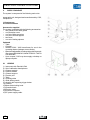
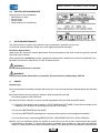
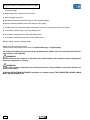
MODÌ 02
90000010
r e v. 0 0 1
03/2014
T
INSTRUCTIONS FOR USE
EN
INSTALLAZIONE
INSTRUCTIONS
FOR USE
Contents
1.
General warnings............................................................................................................. 4
1.1.Symbols.................................................................................................................................. 4
1.2.
Intended use and operating procedures................................................................ 5
1.2.1.Classification...................................................................................................................... 5
1.2.2. Environmental conditions.............................................................................................. 6
1.2.3. REFERENCE STANDARDS....................................................................................................... 6
1.2.4
Warranty
........................................................................................................................... 7
1.3.
Safety warnings................................................................................................................. 8
1.4.Disposal at the end of life............................................................................................. 9
2.
SUPPLY PACKAGE................................................................................................................. 10
2.1LEGEND................................................................................................................................... 10
2.2
IDENTIFICATION NAMEPLATE............................................................................................... 11
3.
ROUTINE MAINTENANCE...................................................................................................... 11
4.USAGE..................................................................................................................................... 11
5.
TECHNICAL FEATURES......................................................................................................... 13
6.
Guidance and manufacturer’s declaration ....................................................... 14
6.1
electromagnetic emission.......................................................................................................... 14
6.2
electromagnetic immunity........................................................................................... 15
INSTALLATION
B1.
INSTALLATION AND COMMISSIONING ................................................................................ 17
B2.
INSTALLATION WITH MULTIPLE FILE INSTRUMENTS......................................................... 18
B2.1
INSTALLING MODI' 02 ON A COMPUTER WITH FIREWIRE ................................................ 18
CONNECTOR TYPE IEEE1394A (6 PIN) ............................................................................... 18
OR IEEE 1394B (9 PIN)........................................................................................................... 18
B2.2
INSTALLING MODI' 02 ON IMAC WITH THUNDERBOLT PORT............................................ 18
B2.3
INSTALLING MODI' 02 TOGETHER WITH ANOTHER INSTRUMENT................................... 18
3
IT
INSTRUCTIONS FOR USE
1.
General warnings
• These instructions describe how to use CSO Modì 02 Corneal Topographic System correctly.
WARNING!
Please carefully read this manual before using the device.
All CSO products have been manufactured with the greatest attention to functionality and safety. In particular:
the Modì 02 corneal topographer is a high-performance system. To use the device effectively and safely, please
read this user manual carefully before installing and using the device, and follow the instructions and warnings
reported in the manual and on the device. Operators who have used the device previously, should check again
the instructions reported in this manual. The manual must be readily available for consultation.
The complete manual consists of this document and of the user manual of the PHOENIX software version
Modì 02, annexed to this document.
The original text of this manual is in Italian.
.
1.1.Symbols
Explanation of Symbols:
1) Type B applied parts, in compliance with EN 60601-1
standards.
2)General Warning indicating the need to carefully
read the user manual before installing and using the
device.
3) Class II device (in compliance with EN 60601:1
standards). This means that the isolation from the
mains supply is highly reliable, therefore no safety
earthing connection is necessary.
4) device classification in accordance with the rules
set out in Annex IX of Directive 93/42/EC and
subsequent amendments: Class I.
The identification number relates to the Notified Body
in
charge of surveillance (IMQ)
5)Disposal symbol incompliance with Directives
2002/95/EC, 2002/96/EC and 2003/108/EC.
6)Manufacturer.
7) ISO 19980 "Optical Instruments - Corneal Topographers"
Standards applicable to instruments for the measurement of the superficial shape of the human
cornea.
IT
ISO 19980
4
INSTRUCTIONS FOR USE
1.2. Intended use and operating procedures
The corneal topographer Modì 02 is an electro medical system for the detection, capturing and digital processing
of an image of the cornea, for ophthalmologic diagnosis by eye specialists.
This system is the result of a long research carried out by recognized professionals to bring new technology,
quality and design together to the highest level.
An absolute innovation in the field of topography, this device allows "live" shooting on the computer monitor.
Thanks to the electronic control of operating functions and the broad operation distance (compared to other
devices of the same type), this device eliminates image decentralisation and focusing errors, ensuring measurement accuracy and repeatability. In addition, the reduced brightness of Placido's rings makes the exam
comfortable for the patient thus guaranteeing ample pupil size.
The video keratoscope is composed of:
-Placido's disk with 24 rings;
-High-resolution monochromatic video camera;
-Management and control software including cornea measurement;
- Provision for integration with the PHOENIX software.
The PHOENIX software Version The Modì 02 allows the following:
- corneal maps display;
- multiple maps comparison in a single display window;
- display window of the differences between two maps and analysis of the differential map;
- management of the patient's medical record and tests check-list to carry out customized statistics and research.
the PHOENIX software includes a section dedicated to contact lenses, providing a printable fluoresceinic simulation of the contact lens on the cornea.
PHOENIX provides an operations environment in which the user can create a set of customized lenses and
add them to template models.
PHOENIX enables printing of the fluoresceinic simulation and of the lenses prescription.
For more detailed information on PHOENIX, please see the "Software User Manual”. 90000002”.
1.2.1.Classification
• MEDICAL DEVICE classification
device classification in accordance with the rules set out in Annex IX of Directive 93/42/EC and subsequent
amendments: Class I.
• ELECTROMEDICAL DEVICES Classification.
Type of protection against direct and indirect contact: Class II (*).
Applied Parts: Type B.
Degree of protection against humidity: Common device (no protection against water seepage) IP20.
Sterilization method: Disinfectable device.
Degree of protection when used with anaesthetics or flammable detergents: No protection.
Conditions of use: Continuous operation
Degree of electrical connection between the device and the patient: Device with parts applied to the patient.
Modì 02 topographers are class II devices, therefore the earth connection and the socket earth serve as
functional earth.
5
IT
INSTRUCTIONS FOR USE
1.2.2.Environmental conditions
As long as the device is kept in its original packaging, it can be exposed to the following environmental conditions without being damaged, and for a maximum period of 15 weeks during shipping and storage:
Operating conditions of use:
Temperature between +10 °C and +35 °C;
Atmospheric pressure 800 hPa to 1060 hPa;
Relative humidity between 30% to 90%.
Storage conditions:
Temperature -10 °C to +55 °C;
Atmospheric pressure 700 hPa to 1060 hPa;
Relative humidity 10% to 95%.
Transport conditions:
Temperature -40 °C to +70 °C;
Atmospheric pressure 500 hPa to 1060 hPa;
Relative humidity 10% to 95%.
Vibration, sinewave 10 Hz to 500 Hz, 0.5g
Shock 30g, time: 6ms
Bumb 10g. time: 6ms
1.2.3.REFERENCE STANDARDS
The following reference standards have been applied for product design, production and control:
Community Directives
• DIRECTIVE 93/42/EEC “MEDICAL DEVICES” OF 14/06/1993 AND SUBSEQUENT AMENDMENTS
• DIRECTIVE 2002/96/EC “Waste Electrical and Electronic Equipment”.
Quality Management System Standards
• UNI EN ISO 9001:2008 “Quality management systems - Requirements”
• UNI EN ISO 13485:2012 “Medical devices - Quality Management Systems - Regulatory Requirements”
Technical Standards
• EN 60601:1 STANDARDS - “PART 1: MEDICAL ELECTRICAL EQUIPMENT: GENERAL
REQUIREMENTS FOR SAFETY", third edition;
• EN 60601-1-2 - “Collateral standard: Electromagnetic Compatibility of Medical Electrical Equipment,
2007 edition;
• UNI EN ISO 15004: “Ophtalmic Instruments - Fundamental Requirements and Testing Methods,
2000 edition;
• UNI EN ISO 15004-1: “Ophthalmic Instruments - Fundamental Requirements and Testing Methods Part 1: General requirements applicable to all Ophtalmic Instruments", 2009 edition;
• UNI EN ISO 15004-2: “Ophthalmic Instruments - Fundamental Requirements and Testing Methods Part 2: Protection against light-related hazards", 2007 edition;
• UNI EN ISO 14971:2012 "Application of risk management to medical devices”
• UNI ISO 19980:2012 "Optical Instruments - Corneal Topographers".
IT
6
INSTRUCTIONS FOR USE
1.2.4 Warranty
CSO S.r.l. is liable for the device being in compliance with the Community Directive 93/42/EEC as amended
by 2007/47/EC, as well as for the device performance, safety and reliability, and consequently for the CE
marking.
CSO S.r.l. will not be liable under the following circumstances:
• installation and commissioning are carried out without following the instructions and precaution warnings
reported in the manual;
• the device is not used following the instructions and precaution warnings reported in the manual;
• accessories or spare parts are used other than those supplied or recommended by CSO S.r.l.;
• repairs and safety controls are not carried out by skilled, qualified personnel, trained and authorised by
CSO S.r.l.;
• the electric system of the location where the device is installed does not comply with CEI standards and
the law requirements in force.
CSO S.r.l. accepts no liability for direct or indirect consequences or for damages to property or harm to persons caused by the improper use of the device or by unsound clinical assumptions based on its use.
CSO S.r.l. warrants this product for a period of 24 months as stated by the date of manufacturing. This warranty
covers the replacement, at CSO premises or at an authorised service centre, of components and materials,
as well as the necessary working hours. Shipping and transportation charges shall be born by the customer.
This warranty does not cover consumable parts or parts likely to wear in normal operation or parts damaged
due to improper use or to maintenance carried out by personnel not authorised by CSO.
OUT OF WARRANTY CONDITIONS
• Repairs of faults caused by natural disasters, mechanical shock (fall, impact, etc.), defects of the electrical
system, neglect, improper use, maintenance or repairs carried out with non original material and/or by
personnel not authorised by CSO S.r.l.
• Any use which is improper or falling out of the intended use as foreseen by the manufacturer.
CSO S.r.l. shall not be liable for any service deficiencies or inefficiencies due to causes or circumstances
beyond its reasonable control. Under no circumstances, shall the customer be entitled to down time damages.
For maintenance or technical information on the device, please contact one of CSO Technical Service Centres or CSO directly at:
CSO srl
Costruzione Strumenti Oftalmici
Via degli Stagnacci, 12/E
50018 Badia a Settimo
Scandicci (FI) - ITALY
Phone: 039(0)55-722191 - FAX 039(0)55-721557
Email: [email protected]
www.csoitalia.it
7
IT
INSTRUCTIONS FOR USE
1.3. Safety warnings
WARNING!
• Do not touch the computer mains power cable with
wet hands; make sure the mains power cable is not
walked on or trapped under weights; do not tie the
mains power cable.
• The power source must have a differential circuit
breaker (IΔn= 30 mA) and a thermal magnetic circuit
breaker(Vn=230V) to protect the device. The power
socket must be close and easily accessible.
• A damaged power cable can cause fire or electric
shock. It must be checked frequently. If the supplied
computer power cable needs to be replaced, please
contact the supplier.
• Do not attempt to carry out any technical intervention
on the device or on the system unless specified in
this manual.
• Do not use the device in the proximity of water and
avoid liquid spillage on any surface of the device.
Avoid humid or dusty places or places which are
subject to rapid fluctuations in temperature and
humidity.
• Unplug the device from the power socket before
cleaning and/or disinfecting.
• The device does not generate or receive electromagnetic interferences when operated near other
devices; no preventive or corrective action is necessary.
• No precautions are necessary in case of any changes affecting the device performance.
• In addition to the image capturing system, the device
includes non electromedical appliances (Personal
Computer, monitor, etc.). The standard configuration
of the system supplied by CSO complies with EN
60601:1 standards (3rd edition), especially as per
the requirements in chapter 16 of said standards.
In addition to its standard configuration, the system
can operate with other appliances (electromedical
and not), therefore CSO could not verify compliance
with the standards of all possible configurations.
• The configuration verified by CSO Srl is the one with
the Personal Computer outside of the patient's area.
• Any peripheral device (printer, scanner, CD player,
etc) connected to the analogical or digital interface
of the system must comply with the following standards:
- EN: 60950-1 for ITE equipment (safety standards
for information technology equipment ); or
- EN 60601:1 for medical electrical equipment;
The peripheral devices must be connected outside
the patient's area.
• After connecting all the peripheral devices, the user
is responsible for regularly verifying compliance of
the electromedical system with EN 60601:1 standards (the specific requirements are reported in
chapter 16 of the standards).
• If leakage current values exceed regulatory limits,
further safety measures must be adopted, as indi-
IT
THE PERSONAL
COMPUTER AND ALL
PERIPHERAL
DEVICES SHOULD
BE PLACED
OUTSIDE THE
PATIENT AREA
The patient area is
the volume defined
as shown in the
figure, within which
the patient may come
into contact
(intentionally or
unintentionally,
directly or through
contact with the
operators) with
medical electrical and
other devices making
up the system
8
INSTRUCTIONS FOR USE
cated in the EN 60601:1 standards (3rd edition). In this case, the overall system must be powered through
an adequate separator or isolation transformer.
- The transformer is absolutely necessary in case the operators cannot easily keep the computer and other
non-electromedical appliances outside of the patients' area.
WARNING!
Only units with CSO trademark can be placed and used in the patient's area.
The following parts of the system must instead be placed outside the patient's area:
• Computer (desktop or laptop), with any peripheral device (monitor, keyboard, mouse, etc.);
• Printers;
• Other non-electromedical auxiliary devices (supply units/battery chargers, UPS, modem, etc.).
If the system needs to be connected to a computer network (LAN) all the necessary measures must be adopted
to prevent transfer of dangerous voltage from remote stations, through the connected cables. The use of data
transfer devices ensuring "GALVANIC ISOLATION" may be necessary.
CSO Srl shall not be held liable in relation to the patient and operator's safety in the case of electrical connections
between the computer and other external units (peripherals) or LAN networks which are not made by CSO Srl itself.
1.4. Disposal at the end of life
Pursuant to Directives 2002/95/EC, 2002/96/EC and 2003/108/EC, on the restriction of hazardous substances
in electrical and electronic equipment and on their disposal.
The device purchased is manufactured using special materials and substances. The device may contain
hazardous substances potentially harmful to the environment or to human health if improperly disposed of
into the environment.
To prevent any hazardous substances from being discharged into the environment and to promote the conservation of natural resources, the manufacturer -should the user want to get rid of the used device at endof-life- facilitates the possible reuse of the device and the recovery and recycling of its materials.
Public authorities adopt adequate measures to make sure that users, distributors and manufacturers contribute
to the collection of electrical and electronic equipment, setting legal requirements for reusing, recovering or
recycling said equipment.
In the case of disposal of the device, specific provisions of European and national law apply, and provide that:
• the device shall not be disposed of as urban waste, it shall be collected separately, by contacting a
company specialising in the disposal of electrical/electronic equipment or the public authorities responsible for waste management;
• in the event that a new piece of equipment is purchased from the same manufacturer to replace an old
one placed on the market before 13 August 2005, equivalent and with the same functions of the new
equipment, the distributor or manufacturer is legally required to collect the old piece of equipment;
• if the user wants to get rid of a used piece of equipment, placed on the market after 13 August 2005, the
distributor or manufacturer is legally required to collect it;
• the manufacturer shall take care of the transport, handling, recovery and/or disposal of the old equipment
collected at its own charge;
• the potentially harmful effects to the environment or human health due to any hazardous substance
contained in electrical and electronic equipment or to the improper use of said equipment or its
parts shall be taken into account.
9
IT
INSTRUCTIONS FOR USE
2.
SUPPLY PACKAGE
The system is composed of the following main units:
topographic unit, designed and manufactured by CSO,
composed of:
1.Keratoscope
2.Phoenix software
Accessories supplied
The system is supplied with the following accessories:
• two guards for the slide guides
• one protection cover
• one set of Allen wrenches
• one set of chinrest papers
• two fuses
• one set of testing spheres
Optionals
• Table
• Chinrest
• Isolation 230V / 230V transformer for use in the
operating theatre (leakage current limiter)
• Motorised adjustable elevating table with telescopic
lifter, brand SCHUMO AG, Model TES2 23 / TA0113
X20 400238Z;
• Upon request, CSO may also supply a desktop or
laptop computer.
2.1LEGEND
1) Instrument with Placido's Disk
2) Set of calibration hemispheres:
3) Chinrest module
4)Patient's handle
5) Chinrest support
6) Firewire port
7)Table
8)Geared guides
9)Glide slides guards
10)Joystick with capturing trigger button
11)Chinrest
12)Base slides locking knob
13)Geared wheels
14)Firewire cable
15)Personal Computer
16)PC power supply cable
IT
10
INSTRUCTIONS FOR USE
2.2 IDENTIFICATION NAMEPLATE
Data reported on the nameplates:
• Manufacturer’s name.
• Device name.
• Serial number.
• Month and year of manufacture.
3.
ROUTINE MAINTENANCE
The system does not require any particular routine maintenance operations by the user.
To clean the external surfaces simply use a cloth slightly dampened with water.
Protection against dust
When not in use, protect the system against dust. Dust accumulating on the device must be regularly removed
with a soft cloth or blower.
Other maintenance operations (repairs, components replacement, assessment of internal components, etc.)
fall within the exclusive competence of CSO Technical Service.
WARNING!
Do not use any thinners or solvents.
WARNING!
If the product needs maintenance, contact the Technical Service authorised by CSO Srl.
4.USAGE
Keratoscopy:
a) Have the patient comfortably sit down with his/her chin on the chinrest and the forehead against the forehead
rest.
b) Lift and lower the chinrest using the handle to align the patient's eyes with
the central eyepiece of the instrument.
c) Enter the Phoenix software; to use the corneal topographer follow the main instructions below:
c1)Press the "New patient" button and key in FIRST NAME and LAST NAME, (if the patient is already in the
database you can launch an automatic query by last or first name) .
c2) Key in the BIRTHDATE and click SAVE.
c3) Key in the BIRTHDATE (these data are compulsory and required by the management software).
c4) Choose the exam mode amongKERATOSCOPY, VIDEOKERATOSCOPY, PUPILLOGRAPHY.
d) Move on to the instrument. Move the Joystick to centre the eye on the monitor, refocus placing the joystick
perpendicular to the table (7). Now pull the joystick completely back towards you, then press and hold the
button (10) while pushing the joystick towards the patient. The capturing will be automatically completed with
11
IT
INSTRUCTIONS FOR USE
a focused image.
e) More images are captured consecutively.
f) Select images to preview.
g) Double-click on each individual image to save the best images.
h) Exit the capturing window to save the images in the gallery.
i) Double-click on the selected image in the gallery to enter the image processing environment.
j) If necessary, edit the rings in the ring editing menu.
k) If necessary, edit pupil size in the pupil editing menu.
l) If necessary, edit limbus size in the limbus editing menu.
m)Click OK to save any changes made.
At this point, the exam is complete.
Please consult the software user manual for Videokeratoscopy or Pupillography.
For further information and access to all image elaborations, please refer to the user manual of the Phoenix software code 90000002.
WARNING!
Do not switch off the computer or disconnect the cable between the Computer and the Topographer
when the programme is running.
WARNING!
To turn off the system, simply follow the usual procedure to exit the software, then switch off the computer power switch.
FOR ISOLATION FROM THE MAINS (condition of complete safety) THE COMPUTER POWER CABLE
MUST BE DISCONNECTED.
IT
12
INSTRUCTIONS FOR USE
5.
TECHNICAL FEATURES
Operation distance
Number of rings
Number of measuring points
Number of points analysed
Diameter of the corneal area covered (at 43 D)
Dioptres measuring arc
Accuracy and repeatability error
Computer
power supply
56 mm
24
6144
Over 100000
0.4 to over 9.6 mm of diameter
1 to 100 D
Class "A" as per "ISO19980:2005 (E)
See computer label
Topographer power supply
Table top size W x D
Topographer size H x W x D
Weight
Through Firewire cable 12 V ± 10% 1A(12VA)
(500 x 405) mm
(470x315x250) mm
4.50 kg
13
IT
INSTRUCTIONS FOR USE
6.
Guidance and manufacturer’s declaration
6.1 electromagnetic emission
Table 1-Guidance and manufacturer’s declaration – electromagnetic emission
The equipment MODI' 02 is intended for use in the electromagnetic environment specified below. The
customer or the end user of the MODI' 02 should assure that it is used in such an environment.
Emission test
compliance
Electromagnetic environment - guidance
RF emission – CISPR 11
Group 1
RF emission – CISPR 11
Class B
Harmonic emission
IEC 61000-3-2
Class A
Voltage fluctuation/flicker emission
IEC 61000-3-3
Complies
IT
The MODI' 02 uses RF energy only for its
internal function. Therefore its emissions are
very low and are not likely to cause any interference in nearby electronic equipment
The MODI' 02 is suitable for use in all establishments including domestic establishments
and those directly connected to the public low
voltage power supply network that supplies
buildings used for domestic purposes
The MODI' 02 is suitable for use in all establishments including domestic establishments
and those directly connected to the public low
voltage power supply network that supplies
buildings used for domestic purposes
The MODI' 02 is suitable for use in all establishments including domestic establishments
and those directly connected to the public low
voltage power supply network that supplies
buildings used for domestic purposes
14
INSTRUCTIONS FOR USE
6.2 electromagnetic immunity.
Table 2 -Guidance and manufacturer’s declaration – electromagnetic immunity
The equipment MODI' 02 is intended for use in the electromagnetic environment specified below. The
customer or the end user of the MODI' 02 should assure that it is used in such an environment.
Immunity test
IEC 60601
Compliance
Electromagnetic environment Test level
level
guidance
Electrostatic discharge (ESD)
IEC 61000-4-2
±6 KV contact
±8 KV air
±6 KV contact
±8 KV air
Floors should be wood, concrete or ceramic tile. If floors are
covered with synthetic material,
the relative humidity should be at
least 30%
Mains power quality should be
that of a typical commercial or
hospital environment
Electrical Fast Transient/Burst
IEC 61000-4-4
±2 KV for power
supply lines
±1 KV for I/O
lines
±2 KV for
power supply
lines
Not applicable
Surge
IEC 61000-4-5
±1 KV differential mode
±2 KV common
mode
±1 KV differen- Mains power quality should be
tial mode
that of a typical commercial or
±2 KV common hospital environment
mode
Voltage Dips, Short interruptions
and voltage variations on power
supply input lines
IEC 61000-4-11
<5% Ut for 0,5
cycle
40% Ut for 5
cycles
70% Ut for 25
cycles
<5% Ut for 5
sec
<5% Ut for 0,5
cycle
40% Ut for 5
cycles
70% Ut for 25
cycles
<5% Ut for 5
sec
Mains power quality should be
that of a typical commercial or
hospital environment.
If the user of the MODI' 02 requires continued operation during
power mains interruptions, it is
recommended that the MODI' 02
be powered from an Uninterruptible Power Supply or Battery
Power frequency (50/60Hz) magnetic field
IEC 61000-4-8
3 A/m
3 A/m
Power frequency magnetic fields
should be at levels characteristic
of a typical location in a typical
commercial or hospital environment
Note: Ut is the AC mains voltage prior to application of the test level
15
IT
INSTRUCTIONS FOR USE
Table 3- Guidance and manufacturer’s declaration – electromagnetic immunity
The equipment MODI' 02 is intended for use in the electromagnetic environment specified below. The
customer or the end user of the MODI' 02 should assure that it is used in such an environment
Immunity test
IEC 60601
Compliance
Electromagnetic environment - guidanTest level
level
ce
Portable and mobile RF communication
equipment should be used no closer
to any part of the MODI' 02, including
cables, than the recommended separation distance calculated from the equation applicable to the frequency of the
transmitter.
Conducted RF
IEC 61000-4-6
3Vrms
150KHz to
80MHz
3 V rms
Radiated RF
IEC 61000-4-3
3V/m
80 MHz to 2,5
GHz
3 V/m
Recommended separation distance.
d=1,167*sqrt (P)
d=1,167*sqrt (P) 80 MHz to 800 MHz
d=2,333*sqrt(P) 800 MHz to 2,5 GHz
Where P is the maximum output power
rating of the transmitter in watts(W) according to the transmitter manufacturer
and d is the recommended separation
distance in metres (m)
Field strengths from fixed RF transmitters, as determined by an electromagnetic site survey, should be less than
the compliance level in each frequency
range. Interference may occur in the
vicinity of equipment marked with the
following symbol:
Note 1: at 80 MHz and 800 MHz, the higher frequency range applies
Note 2: These guidelines may not apply in all situations. Electromagnetic propagation is affected by absorption and reflection from structures, objects and people.
IT
16
INSTALLATION
B1. INSTALLATION AND COMMISSIONING
All equipment composing the system is always delivered
packaged in optimal conditions to withstand standard
transport and storage conditions. In the event that, when
removing the device from its packaging, damages due
to transport are detected, please contact the installer
company or the manufacturer directly.
-Make sure the mains voltage matches the voltage indicated on the AC/DC Adapter and on the computer. If
the voltage does not match contact the technical service
or the manufacturer.
- In Italy, the electrical system must meet IEC 64-4
standards or section 710 or the most recent IEC 64-8
standards (electrical systems in medical environment).
Should you have any doubts, please contact the electrical installation and maintenance company in charge
of your electrical system.
-Do not use multiple sockets, adapters or extension
cables to connect the device plug to the mains socket.
- To disconnect from the power supply, also in case of
emergency, grab the plug of the power cable; do not
pull the power cable to unplug the device.
To assemble the device follow the instructions below:
1) Secure the table top to a base; the instrument holder table is below the device ready for assembly
- proceed as follows:
a)Position the table on the base plate and insert the
screws supplied;
b) Fix the top to the bottom by tightening the four
socket head screws.
2) Unscrew the two socket head screws under the
chinrest. Insert the screws in the chinrest module
and align its holes with the holes of the table top.
Tighten the screws with the wrench provided with
the device.
3)Place the base with orthogonal movements on the
slides on the top part of the instrument table; make
sure that the wheels are aligned.
Lock the device with the knob (12) on the right side
of the base, above the wheels axis.
4) Fix the guards (9) along the slides by inserting the
tags into their slots.
5) Connect the computer to the mains with the cable.
Switch on the computer.
6) If the Phoenix software is not already installed,
follow the instructions on the user manual supplied
with the software to install it.
7)Make the following connections:
- connect the keratoscope to the control unit box
with the cable (17)
- connect the 12V power supply unit to the control
unit box with the cable (20)
- connect the power supply unit to the mains with
the cable (19)
8) Turn on the power supply unit.
9) Connect the control unit box to the computer using
the Firewire cable (14) and the USB cable (18).
10) The system is ready for use.
17
IT
INSTALLATION
The Firewire cable is removable. Modì Firewire
connector is type IEEE 1394A (6 pin).
B2. INSTALLATION WITH MULTIPLE FILE INSTRUMENTS
B2.1 INSTALLING MODI' 02 ON A COMPUTER
WITH FIREWIRE
CONNECTOR TYPE IEEE1394A (6 PIN)
OR IEEE 1394B (9 PIN)
If Modì 02 is used alone, on a personal computer with
type A or B Firewire port, the device can be connected
directly to the PC. An adapter is required (from Firewire
A to Firewire B) only if a type B Firewire connector is
used on the PC.
B2.2 INSTALLING MODI' 02 ON IMAC WITH
THUNDERBOLT PORT.
In this case, the special adapter provided must be used
(code CSO: 3201065 – code Apple:MD464ZM/A).
MAC computers supplied by CSO come with the Thunderbolt adapter as standard equipment.
In addition, when Modì 02 is connected to the Thunderbolt port it must be powered. To power Modì 02 use
the 9-pin HUB (code: 3020058)
and power supply unit 24V, 1.5A (code: 3020070):
3020070.
The adapter, the HUB and the power supply unit must
be connected as shown in the image on the right.
B2.3 INSTALLING MODI' 02 TOGETHER WITH
ANOTHER INSTRUMENT.
If Modì 02 must run together with another device on
the same computer, regardless of the type of port
provided on the computer, the two devices must be
connected to a powered Firewire HUB.
NOTE: 9-pin and 6-pin HUBS are available. 9-pin and
6-pin Firewire cables are available. When placing the
order, make sure all the connectors of the configuration ordered are of the same type.
IT
18